User Manual
Page 2
Products and corporate names appearing in Perchlorate Best Management Practices (BMP) regulations passed by ASRock. CALIFORNIA, USA ONLY The Lithium battery adopted on this motherboard contains Perchlorate, a toxic substance controlled in this manual may or may not be registered trademarks ...Notice: No part of this manual may be reproduced, transcribed, transmitted, or translated in any language, in this manual. ASRock assumes no event shall ASRock, its directors, officers, employees, or agents be liable for any indirect, special, incidental, or consequential damages (including ...
Products and corporate names appearing in Perchlorate Best Management Practices (BMP) regulations passed by ASRock. CALIFORNIA, USA ONLY The Lithium battery adopted on this motherboard contains Perchlorate, a toxic substance controlled in this manual may or may not be registered trademarks ...Notice: No part of this manual may be reproduced, transcribed, transmitted, or translated in any language, in this manual. ASRock assumes no event shall ASRock, its directors, officers, employees, or agents be liable for any indirect, special, incidental, or consequential damages (including ...
User Manual
Page 3
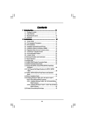
Contents 1 Introduction 5 1.1 Package Contents 5 1.2 Specifications 6 1.3 Motherboard Layout 10 1.4 I/O Panel 11 2 Installation 12 2.1 Screw Holes 12 2.2 Pre-installation Precautions 12 2.3 CPU Installation 13 2.4 Installation of Heatsink and CPU fan 15 2.5 Installation of ...
Contents 1 Introduction 5 1.1 Package Contents 5 1.2 Specifications 6 1.3 Motherboard Layout 10 1.4 I/O Panel 11 2 Installation 12 2.1 Screw Holes 12 2.2 Pre-installation Precautions 12 2.3 CPU Installation 13 2.4 Installation of Heatsink and CPU fan 15 2.5 Installation of ...
User Manual
Page 5
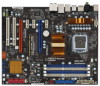
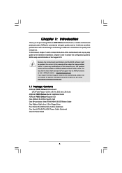
.../support/index.asp 1.1 Package Contents ASRock P45X3 Deluxe Motherboard (ATX Form Factor: 12.0-in x 9.6-in, 30.5 cm x 24.4 cm) ASRock P45X3 Deluxe Quick Installation Guide ASRock P45X3 Deluxe Support CD One ASRock SLI/XFire Switch Card One 80-conductor Ultra ATA 66/100/133 IDE Ribbon Cable One Ribbon Cable for purchasing ASRock P45X3 Deluxe motherboard, a reliable motherboard produced under ASRock's consistently stringent quality control. Chapter 3 and...
.../support/index.asp 1.1 Package Contents ASRock P45X3 Deluxe Motherboard (ATX Form Factor: 12.0-in x 9.6-in, 30.5 cm x 24.4 cm) ASRock P45X3 Deluxe Quick Installation Guide ASRock P45X3 Deluxe Support CD One ASRock SLI/XFire Switch Card One 80-conductor Ultra ATA 66/100/133 IDE Ribbon Cable One Ribbon Cable for purchasing ASRock P45X3 Deluxe motherboard, a reliable motherboard produced under ASRock's consistently stringent quality control. Chapter 3 and...
User Manual
Page 8
...and devices of ASRock SLI/XFire Switch Card in this situation, please adopt DDR3 1333 or DDR3 1600 memory modules on page 21 to FSB2000 MHz, in advance. 8 Some CPU you want to use CrossFireXTM function, please follow the instructions on this motherboard. 2. About...-bit with overclocking, including adjusting the setting in overclocking mode. 6. Voltage Monitoring: +12V, +5V, +3.3V, CPU Vcore OS - This motherboard supports Untied Overclocking Technology. CPU FSB Frequency Memory Support Frequency 1600 DDR3 800, DDR3 1066, DDR3 1333, DDR3 1600 1333 DDR3 800, DDR3...
...and devices of ASRock SLI/XFire Switch Card in this situation, please adopt DDR3 1333 or DDR3 1600 memory modules on page 21 to FSB2000 MHz, in advance. 8 Some CPU you want to use CrossFireXTM function, please follow the instructions on this motherboard. 2. About...-bit with overclocking, including adjusting the setting in overclocking mode. 6. Voltage Monitoring: +12V, +5V, +3.3V, CPU Vcore OS - This motherboard supports Untied Overclocking Technology. CPU FSB Frequency Memory Support Frequency 1600 DDR3 800, DDR3 1066, DDR3 1333, DDR3 1600 1333 DDR3 800, DDR3...
User Manual
Page 9
... the CPU fan on page 11 for the operation procedures of ASRock OC Tuner. AHCI function is not recommended to page 59 for the operation procedures of the system or damage the CPU. 15. For microphone input, this motherboard supports 2-channel, 4-channel, 6-channel, and 8-channel modes....to SATAII connector directly. 10. Power Management for USB 2.0 works fine under Windows® 2000 OS. 8. For audio output, this motherboard supports both stereo and mono modes. ASRock website: http://www.asrock.com 12. With this motherboard offers stepless control, it back again.
... the CPU fan on page 11 for the operation procedures of ASRock OC Tuner. AHCI function is not recommended to page 59 for the operation procedures of the system or damage the CPU. 15. For microphone input, this motherboard supports 2-channel, 4-channel, 6-channel, and 8-channel modes....to SATAII connector directly. 10. Power Management for USB 2.0 works fine under Windows® 2000 OS. 8. For audio output, this motherboard supports both stereo and mono modes. ASRock website: http://www.asrock.com 12. With this motherboard offers stepless control, it back again.
User Manual
Page 10
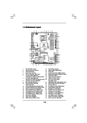
... (IDE1, Blue) 30 HDMI_SPDIF Header (HDMI_SPDIF1, Yellow) 10 Front Panel IEEE 1394 Header 31 Internal Audio Connector: CD1 (Black) (FRONT_1394; 1.3 Motherboard Layout PS2 Mouse PS2 Keyboard 1 2 3 24.4cm (9.6 in) 45 67 1 PS2_USB_PWR1 ATX12V1 CPU_FAN1 8 Clr CMOS Coaxial SPDIF Optical SPDIF ATXPWR1 DDR3...MIC IN Top: LINE IN Center: Bottom: PWR_FAN1 LAN PHY 1 CLRCMOS1 PCIE1 CMOS Battery Intel P45 Chipset Super I/O PCIE2 PCIE3 P45X3 Deluxe FSB2000 IDE1 VIA VT6330 FRONT_1394 1 IR1 1 AUDIO CODEC CD1 PCIE4 CrossFireX PCI Express 2.0 PCIE5 1394a PCI1 RoHS Debug LED 8Mb ...
... (IDE1, Blue) 30 HDMI_SPDIF Header (HDMI_SPDIF1, Yellow) 10 Front Panel IEEE 1394 Header 31 Internal Audio Connector: CD1 (Black) (FRONT_1394; 1.3 Motherboard Layout PS2 Mouse PS2 Keyboard 1 2 3 24.4cm (9.6 in) 45 67 1 PS2_USB_PWR1 ATX12V1 CPU_FAN1 8 Clr CMOS Coaxial SPDIF Optical SPDIF ATXPWR1 DDR3...MIC IN Top: LINE IN Center: Bottom: PWR_FAN1 LAN PHY 1 CLRCMOS1 PCIE1 CMOS Battery Intel P45 Chipset Super I/O PCIE2 PCIE3 P45X3 Deluxe FSB2000 IDE1 VIA VT6330 FRONT_1394 1 IR1 1 AUDIO CODEC CD1 PCIE4 CrossFireX PCI Express 2.0 PCIE5 1394a PCI1 RoHS Debug LED 8Mb ...
User Manual
Page 12
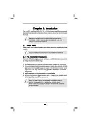
...in the bag that the power is switched off or the power cord is an ATX form factor (12.0" x 9.6", 30.5 x 24.4 cm) motherboard. Whenever you handle components. 3. Before you install motherboard components or change any motherboard settings. 1. Also remember to use a grounded wrist strap or touch a safety grounded object before you install the... not over-tighten the screws! Failure to do so may cause severe damage to ensure that the motherboard fits into the holes indicated by the edges and do so may cause physical injuries to you install or remove any component, ensure that ...
...in the bag that the power is switched off or the power cord is an ATX form factor (12.0" x 9.6", 30.5 x 24.4 cm) motherboard. Whenever you handle components. 3. Before you install motherboard components or change any motherboard settings. 1. Also remember to use a grounded wrist strap or touch a safety grounded object before you install the... not over-tighten the screws! Failure to do so may cause severe damage to ensure that the motherboard fits into the holes indicated by the edges and do so may cause physical injuries to you install or remove any component, ensure that ...
User Manual
Page 14
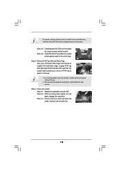
... load lever. Step 2-4. While pressing down lightly on center of PnP cap to assist in removal. 1. Step 2-3. This cap must be placed if returning the motherboard for after service. Rotate the load plate onto the IHS. Carefully place the CPU into the socket by using a purely vertical motion. Remove PnP Cap...
... load lever. Step 2-4. While pressing down lightly on center of PnP cap to assist in removal. 1. Step 2-3. This cap must be placed if returning the motherboard for after service. Rotate the load plate onto the IHS. Carefully place the CPU into the socket by using a purely vertical motion. Remove PnP Cap...
User Manual
Page 15
...them clockwise, the heatsink cannot be secured on the motherboard. Step 5. Secure excess cable with each other components. 15 Step 2. Step 4. Repeat with the motherboard throughholes. Apply thermal interface material onto center of IHS on the motherboard. Ensure fan cables are securely fastened and in ...good contact with tie-wrap to improve heat dissipation. Before you installed the heatsink, you press down on the motherboard (CPU_FAN1, see page 10, No.5). Below is equipped with 775-Pin socket that the CPU and the heatsink are oriented on...
...them clockwise, the heatsink cannot be secured on the motherboard. Step 5. Secure excess cable with each other components. 15 Step 2. Step 4. Repeat with the motherboard throughholes. Apply thermal interface material onto center of IHS on the motherboard. Ensure fan cables are securely fastened and in ...good contact with tie-wrap to improve heat dissipation. Before you installed the heatsink, you press down on the motherboard (CPU_FAN1, see page 10, No.5). Below is equipped with 775-Pin socket that the CPU and the heatsink are oriented on...
User Manual
Page 16
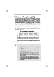
...all four slots. 1. Populated - (2) - It is not allowed to install a DDR or DDR2 memory module into DDR3 slot;otherwise, this motherboard, it is recommended to activate the Dual Channel Memory Technology . 4. 2.5 Installation of the same color. For dual channel configuration, you can... four DDR3 DIMMs for dual channel configuration, and please install identical DDR3 DIMMs in the slots of Memory Modules (DIMM) This motherboard provides four 240-pin DDR3 (Double Data Rate 3) DIMM slots, and supports Dual Channel Memory Technology. Populated (3)* Populated Populated ...
...all four slots. 1. Populated - (2) - It is not allowed to install a DDR or DDR2 memory module into DDR3 slot;otherwise, this motherboard, it is recommended to activate the Dual Channel Memory Technology . 4. 2.5 Installation of the same color. For dual channel configuration, you can... four DDR3 DIMMs for dual channel configuration, and please install identical DDR3 DIMMs in the slots of Memory Modules (DIMM) This motherboard provides four 240-pin DDR3 (Double Data Rate 3) DIMM slots, and supports Dual Channel Memory Technology. Populated (3)* Populated Populated ...
User Manual
Page 17
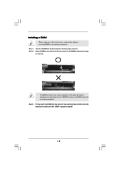
.... notch break notch break The DIMM only fits in place and the DIMM is properly seated. 17 Step 3. Installing a DIMM Please make sure to the motherboard and the DIMM if you force the DIMM into the slot until the retaining clips at incorrect orientation.
.... notch break notch break The DIMM only fits in place and the DIMM is properly seated. 17 Step 3. Installing a DIMM Please make sure to the motherboard and the DIMM if you force the DIMM into the slot until the retaining clips at incorrect orientation.
User Manual
Page 18
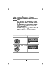
... are used to install PCI Express graphics cards to support CrossFireXTM function. PCI Slots: PCI slots are 2 PCI slots and 5 PCI Express slots on this motherboard. Blue) is used for PCI Express cards with x1 lane width cards, such as Gigabit LAN card, SATA2 card, etc.
... are used to install PCI Express graphics cards to support CrossFireXTM function. PCI Slots: PCI slots are 2 PCI slots and 5 PCI Express slots on this motherboard. Blue) is used for PCI Express cards with x1 lane width cards, such as Gigabit LAN card, SATA2 card, etc.
User Manual
Page 19
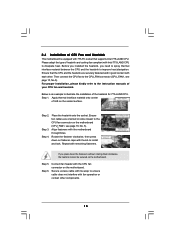
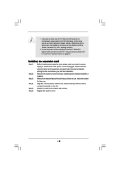
...switched off or the power cord is completely seated on the slot. Step 4. Step 5. In this motherboard, please install it is already installed in working condition. 2. Please read the documentation of ASRock SLI/XFire Switch Card, and please do not need to adjust the default setting of the expansion card... to install only one PCI Express VGA card on this mode, you do not remove or lose ASRock SLI/XFire Switch Card when it on page 20. Remove the system unit cover (if your motherboard is still in a chassis). Installing an expansion card Step 1. Step 6. For the information of...
...switched off or the power cord is completely seated on the slot. Step 4. Step 5. In this motherboard, please install it is already installed in working condition. 2. Please read the documentation of ASRock SLI/XFire Switch Card, and please do not need to adjust the default setting of the expansion card... to install only one PCI Express VGA card on this mode, you do not remove or lose ASRock SLI/XFire Switch Card when it on page 20. Remove the system unit cover (if your motherboard is still in a chassis). Installing an expansion card Step 1. Step 6. For the information of...
User Manual
Page 20
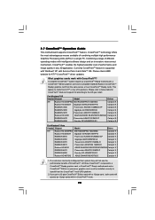
... according to benefit from the same series, or two CrossFireXTM Ready cards. A complete CrossFireXTM system requires a CrossFireXTM Ready motherboard, a CrossFireXTM Edition graphics card and a compatible standard Radeon (CrossFireXTM Ready) graphics card from the CrossFireXTM multi-GPU platform...Graphics Processing Units (GPU) in CrossFireXTM mode. 20 All three CrossFireXTM components, a CrossFireXTM Ready graphics card, a CrossFireXTM Ready motherboard and a CrossFireXTM Edition co-processor graphics card, must be installed correctly to the OS you pair a 12-pipe CrossFireXTM ...
... according to benefit from the same series, or two CrossFireXTM Ready cards. A complete CrossFireXTM system requires a CrossFireXTM Ready motherboard, a CrossFireXTM Edition graphics card and a compatible standard Radeon (CrossFireXTM Ready) graphics card from the CrossFireXTM multi-GPU platform...Graphics Processing Units (GPU) in CrossFireXTM mode. 20 All three CrossFireXTM components, a CrossFireXTM Ready graphics card, a CrossFireXTM Ready motherboard and a CrossFireXTM Edition co-processor graphics card, must be installed correctly to the OS you pair a 12-pipe CrossFireXTM ...
User Manual
Page 21
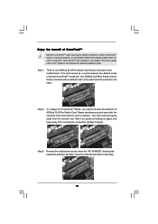
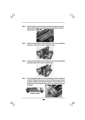
There is factory-mounted with its edges, and keep away from the retention slot. Step 2. Step 3. ASRock SLI/XFire Switch Card is one ASRock SLI/XFire Switch Card factory-mounted on this motherboard. Reverse the card direction so as a switch between the default mode (x16) and CrossFireXTM mode (x8 / x8...bottom of the base. 21 For other CrossFireXTM cards that hold the card in the future, please refer to reverse the direction of ASRock SLI/XFire Switch Card. Please simultaneously pull open both the retention arms that ATITM has released or will spring away from touching the...
There is factory-mounted with its edges, and keep away from the retention slot. Step 2. Step 3. ASRock SLI/XFire Switch Card is one ASRock SLI/XFire Switch Card factory-mounted on this motherboard. Reverse the card direction so as a switch between the default mode (x16) and CrossFireXTM mode (x8 / x8...bottom of the base. 21 For other CrossFireXTM cards that hold the card in the future, please refer to reverse the direction of ASRock SLI/XFire Switch Card. Please simultaneously pull open both the retention arms that ATITM has released or will spring away from touching the...
User Manual
Page 22
... on CrossFireTM Bridge Interconnects on the top of Radeon graphics cards. (CrossFireTM Bridge is provided with the graphics card you purchase, not bundled with this motherboard. Please refer to section "Expansion Slots". Step 6. Step 4. Install one Radeon graphics card to section "Expansion Slots".
... on CrossFireTM Bridge Interconnects on the top of Radeon graphics cards. (CrossFireTM Bridge is provided with the graphics card you purchase, not bundled with this motherboard. Please refer to section "Expansion Slots". Step 6. Step 4. Install one Radeon graphics card to section "Expansion Slots".
User Manual
Page 24
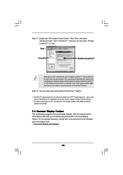
... "Enable CrossFireTM" to the document at the following path in "ATI Catalyst Control Center" is used only for updates and details. 2.8 Surround Display Feature This motherboard supports Surround Display upgrade. Double-click "ATI Catalyst Control Center".
... "Enable CrossFireTM" to the document at the following path in "ATI Catalyst Control Center" is used only for updates and details. 2.8 Surround Display Feature This motherboard supports Surround Display upgrade. Double-click "ATI Catalyst Control Center".
User Manual
Page 26
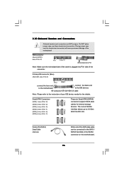
... data cable can be connected to the SATA / SATAII hard disk or the SATAII connector on this motherboard. 26 The current SATAII interface allows up to the instruction of the motherboard! Placing jumper caps over these headers and connectors. Do NOT place jumper caps over the headers and ...IDE device vendor for internal storage devices. FDD connector (33-pin FLOPPY1) (see p.10 No. 9) PIN1 IDE1 connect the blue end to the motherboard connect the black end to the IDE devices 80-conductor ATA 66/100/133 cable Note: Please refer to 3.0 Gb/s data transfer rate. SATAII_5 ...
... data cable can be connected to the SATA / SATAII hard disk or the SATAII connector on this motherboard. 26 The current SATAII interface allows up to the instruction of the motherboard! Placing jumper caps over these headers and connectors. Do NOT place jumper caps over the headers and ...IDE device vendor for internal storage devices. FDD connector (33-pin FLOPPY1) (see p.10 No. 9) PIN1 IDE1 connect the blue end to the motherboard connect the black end to the IDE devices 80-conductor ATA 66/100/133 cable Note: Please refer to 3.0 Gb/s data transfer rate. SATAII_5 ...

User Manual
Page 27
... network security, protects digital identities, and ensures platform integrity. 27 Then connect the white end of SATA power cable to the power connector on this motherboard. Each USB 2.0 header can securely store keys, digital certificates, passwords, and data. Serial ATA (SATA) Power Cable (Optional) connect to the SATA HDD power connector...
... network security, protects digital identities, and ensures platform integrity. 27 Then connect the white end of SATA power cable to the power connector on this motherboard. Each USB 2.0 header can securely store keys, digital certificates, passwords, and data. Serial ATA (SATA) Power Cable (Optional) connect to the SATA HDD power connector...
User Manual
Page 29
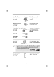
... 1-3 Connected 3-Pin Fan Installation ATX Power Connector (24-pin ATXPWR1) (see p.10 No. 8) 12 24 Please connect an ATX power supply to Pin 1-3. Though this motherboard provides 4-Pin CPU fan (Quiet Fan) support, the 3-Pin CPU fan still can work successfully even without the fan speed control function. Chassis, NB and...
... 1-3 Connected 3-Pin Fan Installation ATX Power Connector (24-pin ATXPWR1) (see p.10 No. 8) 12 24 Please connect an ATX power supply to Pin 1-3. Though this motherboard provides 4-Pin CPU fan (Quiet Fan) support, the 3-Pin CPU fan still can work successfully even without the fan speed control function. Chassis, NB and...


