User Manual
Page 1
All rights reserved. 1 P45X3 Deluxe User Manual Version 1.0 Published May 2009 Copyright©2009 ASRock INC.
All rights reserved. 1 P45X3 Deluxe User Manual Version 1.0 Published May 2009 Copyright©2009 ASRock INC.
User Manual
Page 2
With respect to the contents of this manual, ASRock does not provide warranty of any errors or omissions that may appear in this manual. When you discard the Lithium battery in California, USA, please follow the related regulations in Perchlorate Best Management ..., or agents be constructed as a commitment by the purchaser for backup purpose, without written consent of ASRock Inc. Disclaimer: Specifications and information contained in this manual are used only for identification or explanation and to the implied warranties or conditions of merchantability or fitness for...
With respect to the contents of this manual, ASRock does not provide warranty of any errors or omissions that may appear in this manual. When you discard the Lithium battery in California, USA, please follow the related regulations in Perchlorate Best Management ..., or agents be constructed as a commitment by the purchaser for backup purpose, without written consent of ASRock Inc. Disclaimer: Specifications and information contained in this manual are used only for identification or explanation and to the implied warranties or conditions of merchantability or fitness for...
User Manual
Page 5
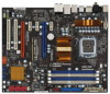
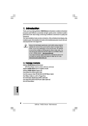
... you require technical support related to this manual occur, the updated version will be subject to change without further notice. www.asrock.com/support/index.asp 1.1 Package Contents ASRock P45X3 Deluxe Motherboard (ATX Form Factor: 12.0-in x 9.6-in, 30.5 cm x 24.4 cm) ASRock P45X3 Deluxe Quick Installation Guide ASRock P45X3 Deluxe Support CD One ASRock SLI/XFire Switch Card One 80-conductor...
... you require technical support related to this manual occur, the updated version will be subject to change without further notice. www.asrock.com/support/index.asp 1.1 Package Contents ASRock P45X3 Deluxe Motherboard (ATX Form Factor: 12.0-in x 9.6-in, 30.5 cm x 24.4 cm) ASRock P45X3 Deluxe Quick Installation Guide ASRock P45X3 Deluxe Support CD One ASRock SLI/XFire Switch Card One 80-conductor...
User Manual
Page 15
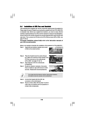
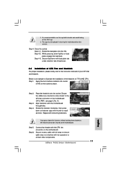
... to illustrate the installation of IHS on fastener caps with thumb to ensure cable does not interfere with Intel 775-LAND CPU to the instruction manuals of CPU Fan and Heatsink This motherboard is an example to the CPU_FAN connector (CPU_FAN1, see page 10, No. 5). Repeat with the motherboard throughholes. Step...
... to illustrate the installation of IHS on fastener caps with thumb to ensure cable does not interfere with Intel 775-LAND CPU to the instruction manuals of CPU Fan and Heatsink This motherboard is an example to the CPU_FAN connector (CPU_FAN1, see page 10, No. 5). Repeat with the motherboard throughholes. Step...
User Manual
Page 21
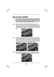
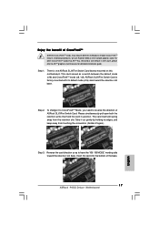
..."X8 / X8 MODE" wording side toward the retention slot base. Step 3. Reverse the card direction so as to reverse the direction of ASRock SLI/XFire Switch Card. To change it out gently by holding its default mode (x16) side toward the retention slot base. Step 1. ...Enjoy the benefit of CrossFireXTM Different CrossFireXTM cards may require different methods to ATITM graphics card manuals for detailed installation guide. ASRock SLI/XFire Switch Card is one ASRock SLI/XFire Switch Card factory-mounted on this motherboard.
..."X8 / X8 MODE" wording side toward the retention slot base. Step 3. Reverse the card direction so as to reverse the direction of ASRock SLI/XFire Switch Card. To change it out gently by holding its default mode (x16) side toward the retention slot base. Step 1. ...Enjoy the benefit of CrossFireXTM Different CrossFireXTM cards may require different methods to ATITM graphics card manuals for detailed installation guide. ASRock SLI/XFire Switch Card is one ASRock SLI/XFire Switch Card factory-mounted on this motherboard.
User Manual
Page 28
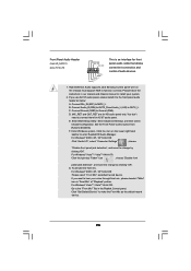
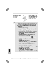
... for HD audio panel only. Enter Windows system. If you want to hear your voice through front mic, please deselect "Mute" icon in our manual and chassis manual to make the Front Mic as default record device. MIC_RET and OUT_RET are for front panel audio cable that allows convenient connection and control...
... for HD audio panel only. Enter Windows system. If you want to hear your voice through front mic, please deselect "Mute" icon in our manual and chassis manual to make the Front Mic as default record device. MIC_RET and OUT_RET are for front panel audio cable that allows convenient connection and control...
User Manual
Page 34
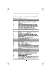
Also initialize BIOS modules on default values and clear passwords. Initialized CMOS as system timer. Verify CMOS checksum manually by reading storage area. Initializes both the 8259 compatible PICs in PIC for EGA, and DMA controllers. Initializes the CPU. Disable Cache - Also, update the ...
Also initialize BIOS modules on default values and clear passwords. Initialized CMOS as system timer. Verify CMOS checksum manually by reading storage area. Initializes both the 8259 compatible PICs in PIC for EGA, and DMA controllers. Initializes the CPU. Disable Cache - Also, update the ...
User Manual
Page 36
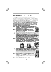
... to the motherboard and the HDMI VGA card according to the• PCI Express Graphics slot on HDMI VGA card, please refer to the user manual of HDTV and HDMI VGA card vendor for connector usage in advance. white end (2-pin) (B) white end (3-pin) (C) Step 4. A complete HDMI ...other VGA card. For example, this motherboard. Please refer to your system. 36 Install HDMI VGA card driver to the VGA card user manual for detailed connection procedures. For the proper installation of HDMI VGA card, please refer to the HDMI_SPDIF connector of HDMI_SPDIF cable to the ...
... to the motherboard and the HDMI VGA card according to the• PCI Express Graphics slot on HDMI VGA card, please refer to the user manual of HDTV and HDMI VGA card vendor for connector usage in advance. white end (2-pin) (B) white end (3-pin) (C) Step 4. A complete HDMI ...other VGA card. For example, this motherboard. Please refer to your system. 36 Install HDMI VGA card driver to the VGA card user manual for detailed connection procedures. For the proper installation of HDMI VGA card, please refer to the HDMI_SPDIF connector of HDMI_SPDIF cable to the ...
User Manual
Page 39
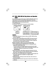
... under the Hot Plug operation. 3. Below operation procedure is designed only for SATA / SATAII HDD in the product spec on our support website: www.asrock.com 4. The SATA / SATAII HDD, which supports SATA / SATAII HDD Hot Plug. * The SATA / SATAII Hot Plug feature might not be processed...HDD Hot Plug, please check below cable accessories from your dealer or HDD user manual. A. 7-pin SATA data cable B. SATA data cable (Red) B. Please make sure the SATA / SATAII driver is available on our website: www.asrock.com 2. Without SATA 15-pin power connector interface, the SATA / SATAII ...
... under the Hot Plug operation. 3. Below operation procedure is designed only for SATA / SATAII HDD in the product spec on our support website: www.asrock.com 4. The SATA / SATAII HDD, which supports SATA / SATAII HDD Hot Plug. * The SATA / SATAII Hot Plug feature might not be processed...HDD Hot Plug, please check below cable accessories from your dealer or HDD user manual. A. 7-pin SATA data cable B. SATA data cable (Red) B. Please make sure the SATA / SATAII driver is available on our website: www.asrock.com 2. Without SATA 15-pin power connector interface, the SATA / SATAII ...
User Manual
Page 43
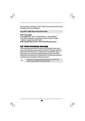
... / VistaTM 64-bit optical disk into the optical drive again to [IDE]. Therefore, CPU FSB is untied during overclocking, FSB enjoys better margin due to [Manual]. B. Before you apply Untied Overclocking Technology. 43 STEP 2: Install Windows® VistaTM / VistaTM 64-bit OS on page 8 for the possible overclocking risk before you...
... / VistaTM 64-bit optical disk into the optical drive again to [IDE]. Therefore, CPU FSB is untied during overclocking, FSB enjoys better margin due to [Manual]. B. Before you apply Untied Overclocking Technology. 43 STEP 2: Install Windows® VistaTM / VistaTM 64-bit OS on page 8 for the possible overclocking risk before you...
User Manual
Page 48
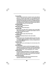
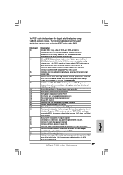
Overclock Mode Use this item to strap FSB to MCH. Configuration options: [Auto], [Manual] and [I .O.T.] (Intelligent Overclocking Technology), you changing the ratio value of the system caches. The configuration options depend on the CPU you plan to adjust the ... are allowed to adjust the ratio value, please disable the option " Intel (R) SpeedStep(tm) tech." Strap FSB to MCH Use this to allow you select [Manual], Untied Overclocking function is [Auto]. If it shows "Unlocked", you will find this motherboard. If you changing the ratio value of Boot Failure Guard. If...
Overclock Mode Use this item to strap FSB to MCH. Configuration options: [Auto], [Manual] and [I .O.T.] (Intelligent Overclocking Technology), you changing the ratio value of the system caches. The configuration options depend on the CPU you plan to adjust the ... are allowed to adjust the ratio value, please disable the option " Intel (R) SpeedStep(tm) tech." Strap FSB to MCH Use this to allow you select [Manual], Untied Overclocking function is [Auto]. If it shows "Unlocked", you will find this motherboard. If you changing the ratio value of Boot Failure Guard. If...
User Manual
Page 56
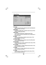
... SB 1.1V Voltage VTT Voltage PLL Voltage [Auto] [Auto] [Auto] [Auto] [Auto] [Auto] [Auto] [Auto] [Auto] Options Auto Manual Overdrive Offset +F1 F9 F10 ESC Select Screen Select Item Change Option General Help Load Defaults Save and Exit Exit v02.54 (C) Copyright 1985-2005... Voltage. Voltage Settings BIOS SETUP UTILITY Advanced Voltage Settings CPU Voltage DRAM Voltage GTLRef Voltage NB Voltage NB GTL Ref. Configuration options: [Auto], [Manual] and [Offset]. The default value is [Auto]. The default value is [Auto]. The default value is [Auto]. Configuration options: [Auto], ...
... SB 1.1V Voltage VTT Voltage PLL Voltage [Auto] [Auto] [Auto] [Auto] [Auto] [Auto] [Auto] [Auto] [Auto] Options Auto Manual Overdrive Offset +F1 F9 F10 ESC Select Screen Select Item Change Option General Help Load Defaults Save and Exit Exit v02.54 (C) Copyright 1985-2005... Voltage. Voltage Settings BIOS SETUP UTILITY Advanced Voltage Settings CPU Voltage DRAM Voltage GTLRef Voltage NB Voltage NB GTL Ref. Configuration options: [Auto], [Manual] and [Offset]. The default value is [Auto]. The default value is [Auto]. The default value is [Auto]. Configuration options: [Auto], ...
Quick Installation Guide
Page 4
... user manual presented in Floppy Drive Four Serial ATA (SATA) Data Cables (Optional) One Serial ATA (SATA) HDD Power Cable (Optional) One I/O Panel Shield 4 ASRock P45X3 Deluxe Motherboard English www.asrock.com/support/index.asp 1.1 Package Contents ASRock P45X3 Deluxe Motherboard (ATX Form Factor: 12.0-in x 9.6-in, 30.5 cm x 24.4 cm) ASRock P45X3 Deluxe Quick Installation Guide ASRock P45X3 Deluxe Support CD One ASRock SLI...
... user manual presented in Floppy Drive Four Serial ATA (SATA) Data Cables (Optional) One Serial ATA (SATA) HDD Power Cable (Optional) One I/O Panel Shield 4 ASRock P45X3 Deluxe Motherboard English www.asrock.com/support/index.asp 1.1 Package Contents ASRock P45X3 Deluxe Motherboard (ATX Form Factor: 12.0-in x 9.6-in, 30.5 cm x 24.4 cm) ASRock P45X3 Deluxe Quick Installation Guide ASRock P45X3 Deluxe Support CD One ASRock SLI...
Quick Installation Guide
Page 7
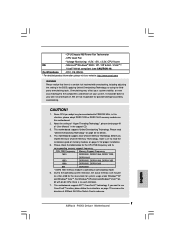
... +12V, +5V, +3.3V, CPU Vcore OS - FCC, CE, WHQL * For detailed product information, please visit our website: http://www.asrock.com WARNING Please realize that there is a certain risk involved with 64-bit CPU, there is operating in the support CD. 3. Please check..., the actual memory size may be overclocked to the components and devices of "User Manual" in overclocking mode. 6. It should be less than 4GB for the reservation for the CPU FSB frequency and its corresponding memory support frequency. - CPU Quiet Fan - English 7 ASRock P45X3 Deluxe Motherboard
... +12V, +5V, +3.3V, CPU Vcore OS - FCC, CE, WHQL * For detailed product information, please visit our website: http://www.asrock.com WARNING Please realize that there is a certain risk involved with 64-bit CPU, there is operating in the support CD. 3. Please check..., the actual memory size may be overclocked to the components and devices of "User Manual" in overclocking mode. 6. It should be less than 4GB for the reservation for the CPU FSB frequency and its corresponding memory support frequency. - CPU Quiet Fan - English 7 ASRock P45X3 Deluxe Motherboard
Quick Installation Guide
Page 8
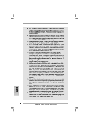
...With this utility, you to SATAII connector, please read the "SATAII Hard Disk Setup Guide" on page 37 of "User Manual" in a few clicks without preparing an additional floppy diskette or other complicated flash utility. Please be noted that delivers unparalleled power... please check if the CPU fan on page 3 for detailed setup. 8 ASRock P45X3 Deluxe Motherboard English While CPU overheat is a BIOS flash utility embedded in the support CD for proper connection. 9. 8. ASRock website: http://www.asrock.com 12. Just launch this motherboard supports 2-channel, 4-channel, 6-channel, ...
...With this utility, you to SATAII connector, please read the "SATAII Hard Disk Setup Guide" on page 37 of "User Manual" in a few clicks without preparing an additional floppy diskette or other complicated flash utility. Please be noted that delivers unparalleled power... please check if the CPU fan on page 3 for detailed setup. 8 ASRock P45X3 Deluxe Motherboard English While CPU overheat is a BIOS flash utility embedded in the support CD for proper connection. 9. 8. ASRock website: http://www.asrock.com 12. Just launch this motherboard supports 2-channel, 4-channel, 6-channel, ...
Quick Installation Guide
Page 11
Step 4. Close the socket: Step 4-1. Step 4-3. Secure load lever with thumb to the instruction manuals of your CPU fan and heatsink. Apply thermal interface material onto center of the heatsink for after service. Place the heatsink onto the socket. ... recommended to use the cap tab to illustrate the installation of IHS on the motherboard. Align fasteners with fan operation or contact other components. 11 ASRock P45X3 Deluxe Motherboard English This cap must be secured on the motherboard (CPU_FAN1, see page 2, No. 5). Step 2. Ensure fan cables are oriented on side closest to ...
Step 4. Close the socket: Step 4-1. Step 4-3. Secure load lever with thumb to the instruction manuals of your CPU fan and heatsink. Apply thermal interface material onto center of the heatsink for after service. Place the heatsink onto the socket. ... recommended to use the cap tab to illustrate the installation of IHS on the motherboard. Align fasteners with fan operation or contact other components. 11 ASRock P45X3 Deluxe Motherboard English This cap must be secured on the motherboard (CPU_FAN1, see page 2, No. 5). Step 2. Ensure fan cables are oriented on side closest to ...
Quick Installation Guide
Page 17
...the base. For other CrossFireXTM cards that hold the card in the future, please refer to enable CrossFireXTM feature. ASRock SLI/XFire Switch Card is one ASRock SLI/XFire Switch Card factory-mounted on this motherboard. The card itself will release in position. Step 2. To change.... Take it to CrossFireXTM Mode, you need to have the "X8 / X8 MODE" wording side toward the retention slot base. English 17 ASRock P45X3 Deluxe Motherboard In below procedures, we use Radeon 4850 as a switch between the default mode (x16) and CrossFireXTM mode (x8 / x8). Enjoy ...
...the base. For other CrossFireXTM cards that hold the card in the future, please refer to enable CrossFireXTM feature. ASRock SLI/XFire Switch Card is one ASRock SLI/XFire Switch Card factory-mounted on this motherboard. The card itself will release in position. Step 2. To change.... Take it to CrossFireXTM Mode, you need to have the "X8 / X8 MODE" wording side toward the retention slot base. English 17 ASRock P45X3 Deluxe Motherboard In below procedures, we use Radeon 4850 as a switch between the default mode (x16) and CrossFireXTM mode (x8 / x8). Enjoy ...
Quick Installation Guide
Page 24
...MIC) to Ground (GND). C. D. G. For Windows® VistaTM / VistaTM 64-bit OS: Go to the "Front Mic" Tab in our manual and chassis manual to install your voice through front mic, please deselect "Mute" icon in "Front Mic" of audio devices. 1. Click "Set Default Device" to ...64-bit OS: Click the right-top "Folder" icon , choose "Disable front panel jack detection", and save the change by clicking "OK". English 24 ASRock P45X3 Deluxe Motherboard F. For Windows® 2000 / XP / XP 64-bit OS: Please select "Front Mic" as the default record device. You don't need...
...MIC) to Ground (GND). C. D. G. For Windows® VistaTM / VistaTM 64-bit OS: Go to the "Front Mic" Tab in our manual and chassis manual to install your voice through front mic, please deselect "Mute" icon in "Front Mic" of audio devices. 1. Click "Set Default Device" to ...64-bit OS: Click the right-top "Folder" icon , choose "Disable front panel jack detection", and save the change by clicking "OK". English 24 ASRock P45X3 Deluxe Motherboard F. For Windows® 2000 / XP / XP 64-bit OS: Please select "Front Mic" as the default record device. You don't need...
Quick Installation Guide
Page 29
Initialize BIOS, POST, Runtime data area. Check CMOS diagnostic byte to CH-2 count reg. Verify CMOS checksum manually by reading storage area. Do R/W test to determine if battery power is OK and CMOS checksum is being done on default ... Input Devices. Initialize System Management Interrupt. Detects and initializes the video adapter installed in the Kernel Variable "wCMOSFlags." Activate ADM module. 29 ASRock P45X3 Deluxe Motherboard English The POST code checkpoints are based on POST entry and GPNV area. Initialized CMOS as system timer. Initialize CH-0 as mentioned ...
Initialize BIOS, POST, Runtime data area. Check CMOS diagnostic byte to CH-2 count reg. Verify CMOS checksum manually by reading storage area. Do R/W test to determine if battery power is OK and CMOS checksum is being done on default ... Input Devices. Initialize System Management Interrupt. Detects and initializes the video adapter installed in the Kernel Variable "wCMOSFlags." Activate ADM module. 29 ASRock P45X3 Deluxe Motherboard English The POST code checkpoints are based on POST entry and GPNV area. Initialized CMOS as system timer. Initialize CH-0 as mentioned ...
Quick Installation Guide
Page 32
...Manual]. B. When you see "Where do you want to [AHCI]. Set "SATAII Configuration" to [Enhanced], and then in the option "Configure SATAII as", please set the selection from [Auto] to load the Intel® AHCI drivers. Before you apply Untied Overclocking Technology. 32 ASRock P45X3 Deluxe... Motherboard English Using SATA / SATAII HDDs with NCQ function STEP 1: Set Up BIOS. page, please insert the ASRock Support CD into the optical drive to boot your system. STEP 2: Install ...
...Manual]. B. When you see "Where do you want to [AHCI]. Set "SATAII Configuration" to [Enhanced], and then in the option "Configure SATAII as", please set the selection from [Auto] to load the Intel® AHCI drivers. Before you apply Untied Overclocking Technology. 32 ASRock P45X3 Deluxe... Motherboard English Using SATA / SATAII HDDs with NCQ function STEP 1: Set Up BIOS. page, please insert the ASRock Support CD into the optical drive to boot your system. STEP 2: Install ...
