User Manual
Page 14
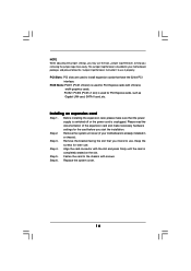
... slot) is used for the card before you removing the jumper caps more easily. PCIE2 / PCIE3 (PCIE x1 slot) is unplugged. Step 4. Align the card connector with the slot and press firmly until the card is already installed in a chassis). NOTE When adjusting the jumper settings, you may use...installation. Replace the system cover. 14 Remove the bracket facing the slot that you intend to install expansion cards that the power supply is switched off or the power cord is used for later use. This Jumper Cap Remover is bundled in your motherboard is completely seated on the slot...
... slot) is used for the card before you removing the jumper caps more easily. PCIE2 / PCIE3 (PCIE x1 slot) is unplugged. Step 4. Align the card connector with the slot and press firmly until the card is already installed in a chassis). NOTE When adjusting the jumper settings, you may use...installation. Replace the system cover. 14 Remove the bracket facing the slot that you intend to install expansion cards that the power supply is switched off or the power cord is used for later use. This Jumper Cap Remover is bundled in your motherboard is completely seated on the slot...

User Manual
Page 15
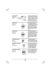
The illustration shows a 3-pin jumper whose pin1 and pin2 are short, both the front panel and the rear panel audio connectors can work. JR1 JL1 Jumper (see p.8, No. 25) JL1 JR1 Note: If the jumpers JL1 and JR1 are "Short" when jumper cap is placed on .... 1) +5V +5VSB +5VSB (standby) for PS/2 or USB wake up the system first, and then shut it requires 2 Amp and higher standby current provided by power supply. When the jumper cap is placed on these 2 pins. After waiting for 5 seconds. Jumper Setting PS2_USB_PW1 1_2 2_3 Short pin2, pin3 to clear the...
The illustration shows a 3-pin jumper whose pin1 and pin2 are short, both the front panel and the rear panel audio connectors can work. JR1 JL1 Jumper (see p.8, No. 25) JL1 JR1 Note: If the jumpers JL1 and JR1 are "Short" when jumper cap is placed on .... 1) +5V +5VSB +5VSB (standby) for PS/2 or USB wake up the system first, and then shut it requires 2 Amp and higher standby current provided by power supply. When the jumper cap is placed on these 2 pins. After waiting for 5 seconds. Jumper Setting PS2_USB_PW1 1_2 2_3 Short pin2, pin3 to clear the...
User Manual
Page 17
... infrared module. L GND A U D - Serial ATA (SATA) Power Cable (Optional) connect to the SATA HDD power connector connect to the power supply Please connect the black end of SATA power cable to the power connector on the I/O panel are not sufficient, this USB 2.0 header is ...available to support 2 additional USB 2.0 ports. Then connect the white end of audio devices. 17 O U T- USB 2.0 Header (9-pin USB45) (see p.8 No. 21) USB_PWR P-7 P+7 GND DUMMY 1 GND P+6 P-6 USB_PWR ASRock ...
... infrared module. L GND A U D - Serial ATA (SATA) Power Cable (Optional) connect to the SATA HDD power connector connect to the power supply Please connect the black end of SATA power cable to the power connector on the I/O panel are not sufficient, this USB 2.0 header is ...available to support 2 additional USB 2.0 ports. Then connect the white end of audio devices. 17 O U T- USB 2.0 Header (9-pin USB45) (see p.8 No. 21) USB_PWR P-7 P+7 GND DUMMY 1 GND P+6 P-6 USB_PWR ASRock ...

User Manual
Page 18
... p.8 No. 18) Chassis Speaker Header (4-pin SPEAKER 1) (see p.8 No. 17) Chassis Fan Connector (3-pin CHA_FAN1) (see p.8 No. 19) CPU Fan Connector (3-pin CPU_FAN1) (see p.8 No. 3) ATX Power Connector (20-pin ATXPWR1) (see p.8 No. 2) Please note that it is installed. 18 ATX 12V Power Connector (4-pin ATX12V1) (see p.8 No. 7) PLED+ PLEDPWRBTN# GND 1 DUMMY RESET# GND HDLEDHDLED+ 1 SPEAKER...
... p.8 No. 18) Chassis Speaker Header (4-pin SPEAKER 1) (see p.8 No. 17) Chassis Fan Connector (3-pin CHA_FAN1) (see p.8 No. 19) CPU Fan Connector (3-pin CPU_FAN1) (see p.8 No. 3) ATX Power Connector (20-pin ATXPWR1) (see p.8 No. 2) Please note that it is installed. 18 ATX 12V Power Connector (4-pin ATX12V1) (see p.8 No. 7) PLED+ PLEDPWRBTN# GND 1 DUMMY RESET# GND HDLEDHDLED+ 1 SPEAKER...

User Manual
Page 19
STEP 2: Connect the SATA power cable to page 30 for details. "RAID" and "non-RAID" mode are options under "SATA Operation Mode" in "RAID" mode. 2. STEP 3: Connect one end of ... (SATA) Hard Disks Installation This motherboard supports Serial ATA (SATA) hard disks and RAID functions. This section will guide you plan to the motherboard's SATA connector.
STEP 2: Connect the SATA power cable to page 30 for details. "RAID" and "non-RAID" mode are options under "SATA Operation Mode" in "RAID" mode. 2. STEP 3: Connect one end of ... (SATA) Hard Disks Installation This motherboard supports Serial ATA (SATA) hard disks and RAID functions. This section will guide you plan to the motherboard's SATA connector.

