
User Manual
Page 3
... 32 3.3.6 Floppy Configuration 33 3.3.7 Super IO Configuration 33 3.3.8 USB Configuration 35 3.4 Hardware Health Event Monitoring Screen 35 3.5 Boot Screen 36 3.5.1 Boot Settings Configuration 36 3.6 Security Screen 37 3.7 Exit Screen 38 3 Installation 10 Pre-installation Precautions 10 2.1 CPU Installation 11 2.2 Installation of CPU Fan and Heatsink 11 2.3 Installation of Memory Modules (DIMM 12 2.4 Expansion Slots (Future CPU Port, PCI and PCI Express Slots) ..... 13 2.5 Jumpers Setup 15 2.6 Onboard Headers and Connectors 16 2.7 Serial ATA (SATA) Hard Disks Installation 19...
... 32 3.3.6 Floppy Configuration 33 3.3.7 Super IO Configuration 33 3.3.8 USB Configuration 35 3.4 Hardware Health Event Monitoring Screen 35 3.5 Boot Screen 36 3.5.1 Boot Settings Configuration 36 3.6 Security Screen 37 3.7 Exit Screen 38 3 Installation 10 Pre-installation Precautions 10 2.1 CPU Installation 11 2.2 Installation of CPU Fan and Heatsink 11 2.3 Installation of Memory Modules (DIMM 12 2.4 Expansion Slots (Future CPU Port, PCI and PCI Express Slots) ..... 13 2.5 Jumpers Setup 15 2.6 Onboard Headers and Connectors 16 2.7 Serial ATA (SATA) Hard Disks Installation 19...
User Manual
Page 5
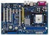
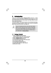
... Serial ATA (SATA) Data Cable (Optional) 1 x Serial ATA (SATA) HDD Power Cable (Optional) 1 x ASRock 8CH I/O Shield 5 Introduction Thank you for purchasing ASRock K8Upgrade-PCIE motherboard, a reliable motherboard produced under ASRock's consistently stringent quality control. You may find the latest memory and CPU support lists on ASRock website without notice. Because the motherboard specifications and the BIOS software might be updated, the content of the Support CD. It delivers excellent performance with robust design conforming to ASRock's commitment to the hardware installation...
... Serial ATA (SATA) Data Cable (Optional) 1 x Serial ATA (SATA) HDD Power Cable (Optional) 1 x ASRock 8CH I/O Shield 5 Introduction Thank you for purchasing ASRock K8Upgrade-PCIE motherboard, a reliable motherboard produced under ASRock's consistently stringent quality control. You may find the latest memory and CPU support lists on ASRock website without notice. Because the motherboard specifications and the BIOS software might be updated, the content of the Support CD. It delivers excellent performance with robust design conforming to ASRock's commitment to the hardware installation...

User Manual
Page 6
... Serial ATA: 2 x SATA Connectors Supports up to 2 SATA Devices at 1.5Gb/s Data Transfer Rate Floppy Port: Supports up to 2 Floppy Disk Drives Audio: 7.1 channels AC'97 Audio LAN: Speed: 802.3u (10/100 Ethernet), Supports Wake-On-LAN Hardware Monitor: CPU Temperature Sensing Motherboard Temperature Sensing CPU Overheat Shutdown to Protect CPU Life (ASRock U-COP)(see CAUTION 3) CPU Fan Tachometer Chassis Fan Tachometer Voltage Monitoring: +12V, +5V, +3.3V, Vcore Future CPU Port: Supports CPU upgrade from AMD 754-Pin CPU to -Use USB 2.0 Ports on the I/O Panel Plus 2 On-Board...
... Serial ATA: 2 x SATA Connectors Supports up to 2 SATA Devices at 1.5Gb/s Data Transfer Rate Floppy Port: Supports up to 2 Floppy Disk Drives Audio: 7.1 channels AC'97 Audio LAN: Speed: 802.3u (10/100 Ethernet), Supports Wake-On-LAN Hardware Monitor: CPU Temperature Sensing Motherboard Temperature Sensing CPU Overheat Shutdown to Protect CPU Life (ASRock U-COP)(see CAUTION 3) CPU Fan Tachometer Chassis Fan Tachometer Voltage Monitoring: +12V, +5V, +3.3V, Vcore Future CPU Port: Supports CPU upgrade from AMD 754-Pin CPU to -Use USB 2.0 Ports on the I/O Panel Plus 2 On-Board...

User Manual
Page 7
... Wake Up Events SMBIOS 2.3.1 Support CPU Frequency Stepless Control (only for proper connection. 6. For audio output, this motherboard supports both stereo and mono modes. During overclocking, FSB enjoys better margin due to perform over-clocking. Before you install the PC system. 4. It may cause the instability of the system or damage the CPU. 7 Frequencies other words, CPU FSB is strongly recommended to enable AMD's Cool 'n' QuietTM technology. 2. Power Management for USB 2.0 works...
... Wake Up Events SMBIOS 2.3.1 Support CPU Frequency Stepless Control (only for proper connection. 6. For audio output, this motherboard supports both stereo and mono modes. During overclocking, FSB enjoys better margin due to perform over-clocking. Before you install the PC system. 4. It may cause the instability of the system or damage the CPU. 7 Frequencies other words, CPU FSB is strongly recommended to enable AMD's Cool 'n' QuietTM technology. 2. Power Management for USB 2.0 works...
User Manual
Page 14
... card connector with screws. Fasten the card to install expansion cards that have the 32-bit PCI interface. Replace the system cover. 14 Step 2. Keep the screws for the card before you start the installation. Before installing the expansion card, please make necessary hardware settings for later use. Remove the bracket facing the slot that the power supply is switched off or the power cord is used for PCI Express cards with x16 lane width graphics cards. PCI Slots: PCI slots...
... card connector with screws. Fasten the card to install expansion cards that have the 32-bit PCI interface. Replace the system cover. 14 Step 2. Keep the screws for the card before you start the installation. Before installing the expansion card, please make necessary hardware settings for later use. Remove the bracket facing the slot that the power supply is switched off or the power cord is used for PCI Express cards with x16 lane width graphics cards. PCI Slots: PCI slots...

User Manual
Page 16
... IDE connector (IDE2, black). Serial ATA (SATA) Data Cable Either end of the SATA data cable can be connected to optimize compatibility and performance, please connect your IDE device vendor for internal storage devices. Besides, to the SATA hard disk or the SATA connector on this motherboard, please set the IDE device as "Master". Primary IDE Connector (Blue) (39-pin IDE1, see p.8 No. 13) Secondary IDE Connector (Black) (39-pin IDE2, see p.8 No. 16) SATA1 SATA2 These two Serial ATA (SATA) connectors support SATA data cables...
... IDE connector (IDE2, black). Serial ATA (SATA) Data Cable Either end of the SATA data cable can be connected to optimize compatibility and performance, please connect your IDE device vendor for internal storage devices. Besides, to the SATA hard disk or the SATA connector on this motherboard, please set the IDE device as "Master". Primary IDE Connector (Blue) (39-pin IDE1, see p.8 No. 13) Secondary IDE Connector (Black) (39-pin IDE2, see p.8 No. 16) SATA1 SATA2 These two Serial ATA (SATA) connectors support SATA data cables...
User Manual
Page 17
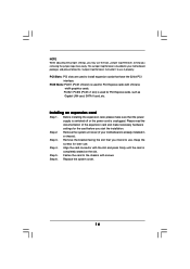
... support 2 additional USB 2.0 ports. USB 2.0 Header (9-pin USB45) (see p.8 No. 21) USB_PWR P-7 P+7 GND DUMMY 1 GND P+6 P-6 USB_PWR ASRock 8CH I/O accommodates 4 default USB 2.0 ports. If those USB 2.0 ports on the I/O panel are not sufficient, this USB 2.0 header is available to receive stereo audio input from sound sources such as a CD-ROM, DVD-ROM, TV tuner card, or MPEG card. O U T- R MIC-POWER MIC This is an interface for front panel audio cable that allows convenient connection and control of audio devices. 17 Serial ATA (SATA) Power Cable (Optional) connect...
... support 2 additional USB 2.0 ports. USB 2.0 Header (9-pin USB45) (see p.8 No. 21) USB_PWR P-7 P+7 GND DUMMY 1 GND P+6 P-6 USB_PWR ASRock 8CH I/O accommodates 4 default USB 2.0 ports. If those USB 2.0 ports on the I/O panel are not sufficient, this USB 2.0 header is available to receive stereo audio input from sound sources such as a CD-ROM, DVD-ROM, TV tuner card, or MPEG card. O U T- R MIC-POWER MIC This is an interface for front panel audio cable that allows convenient connection and control of audio devices. 17 Serial ATA (SATA) Power Cable (Optional) connect...

User Manual
Page 18
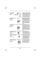
Please connect an ATX power supply to this connector. ATX 12V Power Connector (4-pin ATX12V1) (see p.8 No. 2) Please note that it is necessary to connect a power supply with ATX 12V plug to this header if the Game port bracket is installed. 18 Please connect a chassis fan cable to this connector. Game Port Header (15-pin GAME1) (see p.8 No. 7) PLED+ PLEDPWRBTN# GND 1 DUMMY RESET# GND HDLEDHDLED+ 1 SPEAKER DUMMY DUMMY +5V GND +12V CHA_FAN_SPEED This header accommodates several system front panel functions...
Please connect an ATX power supply to this connector. ATX 12V Power Connector (4-pin ATX12V1) (see p.8 No. 2) Please note that it is necessary to connect a power supply with ATX 12V plug to this header if the Game port bracket is installed. 18 Please connect a chassis fan cable to this connector. Game Port Header (15-pin GAME1) (see p.8 No. 7) PLED+ PLEDPWRBTN# GND 1 DUMMY RESET# GND HDLEDHDLED+ 1 SPEAKER DUMMY DUMMY +5V GND +12V CHA_FAN_SPEED This header accommodates several system front panel functions...

User Manual
Page 20
... the Support CD: .. \ RAID BIOS Setting Utility You may start to use "SiS RAID BIOS Setting Utility" to set the RAID configuration by SATA operating in RAID mode, and you don't need to boot your system, or you start to configure the RAID function, you need to make a SATA driver before you may also set RAID 0 / RAID 1 / JBOD configuration before OS installation. 20 Formatting the floppy diskette will start to SATA Hard Disks Installation and RAID Configuration", at the beginning of system boot-up, press key, and then a window...
... the Support CD: .. \ RAID BIOS Setting Utility You may start to use "SiS RAID BIOS Setting Utility" to set the RAID configuration by SATA operating in RAID mode, and you don't need to boot your system, or you start to configure the RAID function, you need to make a SATA driver before you may also set RAID 0 / RAID 1 / JBOD configuration before OS installation. 20 Formatting the floppy diskette will start to SATA Hard Disks Installation and RAID Configuration", at the beginning of system boot-up, press key, and then a window...
User Manual
Page 25
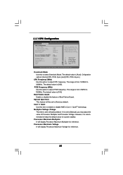
... and voltage will display Processor Maximum Voltage for system stability. 3.3.1 CPU Configuration Advanced BIOS SETUP UTILITY CPU Configuration Overclock Mode CPU Frequency (Mhz) PCIE Frequency (MHz) Boot Failure Guard Spread Spectrum Cool' n' Quiet Multiplier/Voltage Change Processor Maximum Multiplier Processor Maximum Voltage Memory Clock Flexibility Option Burst Length CAS Latency (CL) TRCD TRAS TRP [Auto] [200] [100] [Enabled] [Auto] [Enabled] [Auto] x11 1.550 V [Auto] [Disabled] [8 Beats] [Auto] [Auto] [Auto] [Auto] If AUTO, multiplier and voltage will display Processor Maximum...
... and voltage will display Processor Maximum Voltage for system stability. 3.3.1 CPU Configuration Advanced BIOS SETUP UTILITY CPU Configuration Overclock Mode CPU Frequency (Mhz) PCIE Frequency (MHz) Boot Failure Guard Spread Spectrum Cool' n' Quiet Multiplier/Voltage Change Processor Maximum Multiplier Processor Maximum Voltage Memory Clock Flexibility Option Burst Length CAS Latency (CL) TRCD TRAS TRP [Auto] [200] [100] [Enabled] [Auto] [Enabled] [Auto] x11 1.550 V [Auto] [Disabled] [8 Beats] [Auto] [Auto] [Auto] [Auto] If AUTO, multiplier and voltage will display Processor Maximum...
User Manual
Page 27
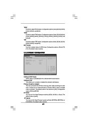
... Configuration BIOS SETUP UTILITY Advanced Chipset Settings OnBoard AC97 Audio OnBoard LAN Primary Graphics Adapter [Auto] [Enabled] [PCI] HT Width HT Speed DRAM Voltage [Auto] [Auto] [Auto] Enable/Disable onboard Audio device. +F1 F9 F10 ESC Select Screen Select Item Change Option General Help Load Defaults Save and Exit Exit v02.54 (C) Copyright 1985-2003, American Megatrends, Inc. Configuration options: [Auto], [5CLK], [6CLK], [7CLK], [8CLK], [9CLK], [10CLK], [11CLK], [12CLK], [13CLK], [14CLK], and [15CLK]. The default value is [Auto]. 27 Configuration options: [PCI] and [PCIE...
... Configuration BIOS SETUP UTILITY Advanced Chipset Settings OnBoard AC97 Audio OnBoard LAN Primary Graphics Adapter [Auto] [Enabled] [PCI] HT Width HT Speed DRAM Voltage [Auto] [Auto] [Auto] Enable/Disable onboard Audio device. +F1 F9 F10 ESC Select Screen Select Item Change Option General Help Load Defaults Save and Exit Exit v02.54 (C) Copyright 1985-2003, American Megatrends, Inc. Configuration options: [Auto], [5CLK], [6CLK], [7CLK], [8CLK], [9CLK], [10CLK], [11CLK], [12CLK], [13CLK], [14CLK], and [15CLK]. The default value is [Auto]. 27 Configuration options: [PCI] and [PCIE...
User Manual
Page 28
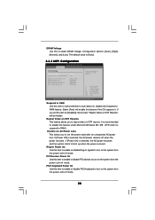
... [Auto]. 3.3.3 ACPI Configuration BIOS SETUP UTILITY Advanced ACPI Settings Suspend To RAM Repost Video on STR Resume Restore on STR Resume" will enable this item to select DRAM voltage. Suspend to RAM Use this to [Disabled], the function "Repost Video on AC / Power Loss Ring-In Power On PCI Devices Power On PS / 2 Keyboard Power On RTC Alarm Power On [Auto] [No] [Power Off] [Disabled] [Disabled] [Disabled] [Disabled] Select auto-detect or disable the STR feature. +F1 F9 F10 ESC Select Screen Select Item Change Option...
... [Auto]. 3.3.3 ACPI Configuration BIOS SETUP UTILITY Advanced ACPI Settings Suspend To RAM Repost Video on STR Resume Restore on STR Resume" will enable this item to select DRAM voltage. Suspend to RAM Use this to [Disabled], the function "Repost Video on AC / Power Loss Ring-In Power On PCI Devices Power On PS / 2 Keyboard Power On RTC Alarm Power On [Auto] [No] [Power Off] [Disabled] [Disabled] [Disabled] [Disabled] Select auto-detect or disable the STR feature. +F1 F9 F10 ESC Select Screen Select Item Change Option...

User Manual
Page 29
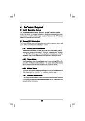
... Use this item to enable or disable RTC (Real Time Clock) to power on the system. 3.3.4 IDE Configuration Advanced BIOS SETUP UTILITY IDE Configuration OnBoard IDE Controller OnBoard SATA Controller SATA Operation Mode Primary IDE Master Primary IDE Slave Secondary IDE Master Secondary IDE Slave SATA1 SATA2 [Both] [Enabled] [RAID] [Hard Disk] [Not Detected] [ATAPI CDROM] [Not Detected] [Not Detected] [Not Detected] DISABLED: disables the integrated IDE Controller. BOTH: enables both IDE Controllers. +F1 F9 F10 ESC Select Screen Select Item Change Option General Help Load Defaults...
... Use this item to enable or disable RTC (Real Time Clock) to power on the system. 3.3.4 IDE Configuration Advanced BIOS SETUP UTILITY IDE Configuration OnBoard IDE Controller OnBoard SATA Controller SATA Operation Mode Primary IDE Master Primary IDE Slave Secondary IDE Master Secondary IDE Slave SATA1 SATA2 [Both] [Enabled] [RAID] [Hard Disk] [Not Detected] [ATAPI CDROM] [Not Detected] [Not Detected] [Not Detected] DISABLED: disables the integrated IDE Controller. BOTH: enables both IDE Controllers. +F1 F9 F10 ESC Select Screen Select Item Change Option General Help Load Defaults...

User Manual
Page 30
...]. The default value of "Primary IDE Slave", "Secondary IDE Master", and "Secondary IDE Slave" as below. Configuration options: [IDE], and [SATA]. 30 However, if you plug PCIE-SATA2 card to [Disabled] will use the "Primary IDE Master" as the example in the following instruction, which can be as well. Advanced BIOS SETUP UTILITY IDE Configuration OnBoard IDE Controller OnBoard SATA Controller SATA Operation Mode PCIE-SATA2 Operation Mode Primary IDE Master Primary IDE Slave Secondary IDE Master Secondary IDE Slave SATA1 SATA2 PCIE-SATA2 Card [Both] [Enabled] [RAID] [IDE] [Hard Disk...
...]. The default value of "Primary IDE Slave", "Secondary IDE Master", and "Secondary IDE Slave" as below. Configuration options: [IDE], and [SATA]. 30 However, if you plug PCIE-SATA2 card to [Disabled] will use the "Primary IDE Master" as the example in the following instruction, which can be as well. Advanced BIOS SETUP UTILITY IDE Configuration OnBoard IDE Controller OnBoard SATA Controller SATA Operation Mode PCIE-SATA2 Operation Mode Primary IDE Master Primary IDE Slave Secondary IDE Master Secondary IDE Slave SATA1 SATA2 PCIE-SATA2 Card [Both] [Enabled] [RAID] [IDE] [Hard Disk...

User Manual
Page 32
... keep the default value unless the installed PCI expansion cards' specifications require other settings. PCI Latency Timer The default value is recommended to malfunction. Setting wrong values in this item to enable 32-bit access to maximize the IDE hard disk data transfer rate. 3.3.5 PCIPnP Configuration BIOS SETUP UTILITY Advanced Advanced PCI / PnP Settings WARNING: Setting wrong values in units of PCI clocks for PCI device latency timer register. It is 32. Configuration options: [Disabled], [Auto], [Enabled]. 32-Bit Data Transfer Use this...
... keep the default value unless the installed PCI expansion cards' specifications require other settings. PCI Latency Timer The default value is recommended to malfunction. Setting wrong values in this item to enable 32-bit access to maximize the IDE hard disk data transfer rate. 3.3.5 PCIPnP Configuration BIOS SETUP UTILITY Advanced Advanced PCI / PnP Settings WARNING: Setting wrong values in units of PCI clocks for PCI device latency timer register. It is 32. Configuration options: [Disabled], [Auto], [Enabled]. 32-Bit Data Transfer Use this...

User Manual
Page 33
.... OnBoard Floppy Controller Use this item to enable or disable floppy drive controller. Infrared Port Address Use this section, you may configure the type of floppy drive connected to the system. +F1 F9 F10 ESC Select Screen Select Item Change Option General Help Load Defaults Save and Exit Exit v02.54 (C) Copyright 1985-2003, American Megatrends, Inc. 3.3.7 Super IO Configuration BIOS SETUP UTILITY Advanced Configure Super IO Chipset OnBoard Floppy Controller Serial Port Address Infrared Port Address Parallel Port Address Parallel Port Mode EPP Version ECP Mode DMA Channel...
.... OnBoard Floppy Controller Use this item to enable or disable floppy drive controller. Infrared Port Address Use this section, you may configure the type of floppy drive connected to the system. +F1 F9 F10 ESC Select Screen Select Item Change Option General Help Load Defaults Save and Exit Exit v02.54 (C) Copyright 1985-2003, American Megatrends, Inc. 3.3.7 Super IO Configuration BIOS SETUP UTILITY Advanced Configure Super IO Chipset OnBoard Floppy Controller Serial Port Address Infrared Port Address Parallel Port Address Parallel Port Mode EPP Version ECP Mode DMA Channel...

User Manual
Page 35
... the legacy USB support. 3.4 Hardware Health Event Monitoring Screen In this item to enable or disable the support to monitor the status of the hardware on your system, including the parameters of USB controller. etc. if there is no USB device connected, "Auto" option will start to enable or disable the use of the CPU temperature, motherboard temperature, CPU fan speed, chassis fan speed, and the critical voltage. BIOS SETUP UTILITY Main Advanced H/W Monitor Boot Security Exit Hardware Health Event Monitoring CPU Temperature M / B Temperature CPU Fan Speed Chassis Fan Speed Vcore...
... the legacy USB support. 3.4 Hardware Health Event Monitoring Screen In this item to enable or disable the support to monitor the status of the hardware on your system, including the parameters of USB controller. etc. if there is no USB device connected, "Auto" option will start to enable or disable the use of the CPU temperature, motherboard temperature, CPU fan speed, chassis fan speed, and the critical voltage. BIOS SETUP UTILITY Main Advanced H/W Monitor Boot Security Exit Hardware Health Event Monitoring CPU Temperature M / B Temperature CPU Fan Speed Chassis Fan Speed Vcore...

User Manual
Page 36
... Main Advanced BIOS SETUP UTILITY H/W Monitor Boot Security Exit Boot Settings Boot Settings Configuration 1st Boot Device 2nd Boot Device 3rd Boot Device Removable Drives [1st Floppy Device] [HDD: PM-MAXTOR 6L08] [CD/DVD: SM-CD-ROM] Configure Settings during System Boot. Boot Up Num-Lock If this item to Sub Screen F1 General Help F9 Load Defaults F10 Save and Exit ESC Exit v02.54 (C) Copyright 1985-2003, American Megatrends, Inc. 3.5.1 Boot Settings Configuration BIOS SETUP UTILITY Boot Boot Settings Configuration Boot From Network Bootup Num-Lock [Disabled] [On] To enable...
... Main Advanced BIOS SETUP UTILITY H/W Monitor Boot Security Exit Boot Settings Boot Settings Configuration 1st Boot Device 2nd Boot Device 3rd Boot Device Removable Drives [1st Floppy Device] [HDD: PM-MAXTOR 6L08] [CD/DVD: SM-CD-ROM] Configure Settings during System Boot. Boot Up Num-Lock If this item to Sub Screen F1 General Help F9 Load Defaults F10 Save and Exit ESC Exit v02.54 (C) Copyright 1985-2003, American Megatrends, Inc. 3.5.1 Boot Settings Configuration BIOS SETUP UTILITY Boot Boot Settings Configuration Boot From Network Bootup Num-Lock [Disabled] [On] To enable...
User Manual
Page 39
... about ASRock, welcome to display the menus. 4.2.2 Drivers Menu The Drivers Menu shows the available devices drivers including ASRock Express GbL PCI Express LAN card driver if the system detects the installed devices. The CD automatically displays the Main Menu if "AUTORUN" is enabled in this chapter for further information. 39 4. Because motherboard settings and hardware options vary, use the setup procedures in your dealer for general reference only. Software Support 4.1 Install Operating System This motherboard supports various Microsoft® Windows®...
... about ASRock, welcome to display the menus. 4.2.2 Drivers Menu The Drivers Menu shows the available devices drivers including ASRock Express GbL PCI Express LAN card driver if the system detects the installed devices. The CD automatically displays the Main Menu if "AUTORUN" is enabled in this chapter for further information. 39 4. Because motherboard settings and hardware options vary, use the setup procedures in your dealer for general reference only. Software Support 4.1 Install Operating System This motherboard supports various Microsoft® Windows®...
User Manual
Page 40
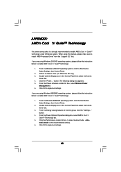
.... 4. Double-click the Display icon in the Control Panel then select the Screen Saver tab. 3. When using Windows 98SE/ME operating system, please follow the instruction below to select desired mode. From the Power schemes combo list box, select Minimal Power Management. 6. Automatic mode is strongly recommended to install "AMD Processor Driver" from the "Support CD" first. APPENDIX: AMD's Cool 'n' QuietTM Technology For power-saving sake, it is the recommended setting. 6.
.... 4. Double-click the Display icon in the Control Panel then select the Screen Saver tab. 3. When using Windows 98SE/ME operating system, please follow the instruction below to select desired mode. From the Power schemes combo list box, select Minimal Power Management. 6. Automatic mode is strongly recommended to install "AMD Processor Driver" from the "Support CD" first. APPENDIX: AMD's Cool 'n' QuietTM Technology For power-saving sake, it is the recommended setting. 6.


