User Manual
Page 8
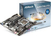
... x Front Panel Audio Connector • 1 x Analog Surround Audio Header • 1 x Digital MIC Header • 1 x 3W Audio AMP Output Wafer Header • 1 x SATA Power Connector • 2 x USB 2.0 Headers (Support 4 USB 2.0 ports) • 32Mb AMI UEFI Legal BIOS with multilingual GUI support • ACPI 1.1 Compliant wake up events •... 8.1 64-bit / 8 32-bit / 8 64bit / 7 32-bit / 7 64-bit Certifications • FCC, CE, WHQL • ErP/EuP Ready (ErP/EuP ready power supply is required) * For detailed product information, please visit our website: http://www.asrock.com English 4
... x Front Panel Audio Connector • 1 x Analog Surround Audio Header • 1 x Digital MIC Header • 1 x 3W Audio AMP Output Wafer Header • 1 x SATA Power Connector • 2 x USB 2.0 Headers (Support 4 USB 2.0 ports) • 32Mb AMI UEFI Legal BIOS with multilingual GUI support • ACPI 1.1 Compliant wake up events •... 8.1 64-bit / 8 32-bit / 8 64bit / 7 32-bit / 7 64-bit Certifications • FCC, CE, WHQL • ErP/EuP Ready (ErP/EuP ready power supply is required) * For detailed product information, please visit our website: http://www.asrock.com English 4
User Manual
Page 23
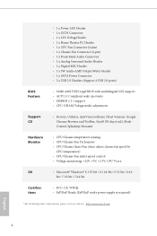
mini-PCIe slot: MINI_PCIE1 (mini-PCIe slot) is unplugged. Before installing an expansion card, please make necessary hardware settings for the card before you start the installation. Please read the documentation of the expansion card and make sure that the power supply is switched off or the power cord is used for WiFi module. 19 English PCIe slot: PCIE1 (PCIe 2.0 x4 slot) is 1 PCI Express slot and 1 mini PCI Express slot on this motherboard. H81TM-ITX 2.4 Expansion Slots (PCI Express Slots) There is used for PCI Express x4 lane width cards.
mini-PCIe slot: MINI_PCIE1 (mini-PCIe slot) is unplugged. Before installing an expansion card, please make necessary hardware settings for the card before you start the installation. Please read the documentation of the expansion card and make sure that the power supply is switched off or the power cord is used for WiFi module. 19 English PCIe slot: PCIE1 (PCIe 2.0 x4 slot) is 1 PCI Express slot and 1 mini PCI Express slot on this motherboard. H81TM-ITX 2.4 Expansion Slots (PCI Express Slots) There is used for PCI Express x4 lane width cards.
User Manual
Page 24
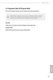
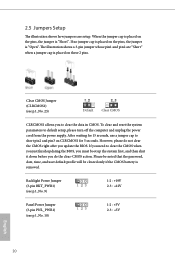
Clear CMOS Jumper (CLRCMOS1) (see p.9, No. 10) 1-2 : +3V 2-3 : +5V 20 English Backlight Power Jumper (3-pin BKT_PWR1) (see p.9, No. 9) 1-2 : +19V 2-3 : +12V Panel Power Jumper (3-pin PNL_PWR1) (see p.9, No. 23) Default Clear CMOS CLRCMOS1 allows you to clear the CMOS when you just finish updating the BIOS, you must ... the pins, the jumper is placed on CLRCMOS1 for 15 seconds, use a jumper cap to default setup, please turn off the computer and unplug the power cord from the power supply.
Clear CMOS Jumper (CLRCMOS1) (see p.9, No. 10) 1-2 : +3V 2-3 : +5V 20 English Backlight Power Jumper (3-pin BKT_PWR1) (see p.9, No. 9) 1-2 : +19V 2-3 : +12V Panel Power Jumper (3-pin PNL_PWR1) (see p.9, No. 23) Default Clear CMOS CLRCMOS1 allows you to clear the CMOS when you just finish updating the BIOS, you must ... the pins, the jumper is placed on CLRCMOS1 for 15 seconds, use a jumper cap to default setup, please turn off the computer and unplug the power cord from the power supply.
Quick Installation Guide
Page 8
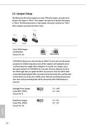
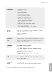
H81TM-ITX Connector • 1 x Power LED Header • 1 x LVDS Connector • 1 x LPC Debug Header • 1 x Home Theater PC Header • 1 x CPU Fan Connector (4-pin) • 1 x Chassis Fan Connector (4-pin) • 1 x Front Panel Audio Connector • 1 x Analog Surround Audio Header • 1 x Digital MIC Header • 1 x 3W Audio AMP Output Wafer Header • 1 x SATA Power... • FCC, CE, WHQL • ErP/EuP Ready (ErP/EuP ready power supply is required) * For detailed product information, please visit our website: http://www.asrock.com English 7
H81TM-ITX Connector • 1 x Power LED Header • 1 x LVDS Connector • 1 x LPC Debug Header • 1 x Home Theater PC Header • 1 x CPU Fan Connector (4-pin) • 1 x Chassis Fan Connector (4-pin) • 1 x Front Panel Audio Connector • 1 x Analog Surround Audio Header • 1 x Digital MIC Header • 1 x 3W Audio AMP Output Wafer Header • 1 x SATA Power... • FCC, CE, WHQL • ErP/EuP Ready (ErP/EuP ready power supply is required) * For detailed product information, please visit our website: http://www.asrock.com English 7

Quick Installation Guide
Page 20
mini-PCIe slot: MINI_PCIE1 (mini-PCIe slot) is used for WiFi module. 19 English PCIe slot: PCIE1 (PCIe 2.0 x4 slot) is used for the card before you start the installation. H81TM-ITX 2.4 Expansion Slots (PCI Express Slots) There is unplugged. Before installing an expansion card, please make necessary hardware settings for PCI Express x4 lane width cards. Please read the documentation of the expansion card and make sure that the power supply is switched off or the power cord is 1 PCI Express slot and 1 mini PCI Express slot on this motherboard.
mini-PCIe slot: MINI_PCIE1 (mini-PCIe slot) is used for WiFi module. 19 English PCIe slot: PCIE1 (PCIe 2.0 x4 slot) is used for the card before you start the installation. H81TM-ITX 2.4 Expansion Slots (PCI Express Slots) There is unplugged. Before installing an expansion card, please make necessary hardware settings for PCI Express x4 lane width cards. Please read the documentation of the expansion card and make sure that the power supply is switched off or the power cord is 1 PCI Express slot and 1 mini PCI Express slot on this motherboard.
Quick Installation Guide
Page 21
... and pin3 on CLRCMOS1 for 15 seconds, use a jumper cap to default setup, please turn off the computer and unplug the power cord from the power supply. After waiting for 5 seconds. Please be noted that the password, date, time, and user default profile will be cleared only... if the CMOS battery is removed. Backlight Power Jumper (3-pin BKT_PWR1) (see p.1, No. 9) 1-2 : +19V 2-3 : +12V Panel Power Jumper (3-pin PNL_PWR1) (see p.1, No. 23) Default...
... and pin3 on CLRCMOS1 for 15 seconds, use a jumper cap to default setup, please turn off the computer and unplug the power cord from the power supply. After waiting for 5 seconds. Please be noted that the password, date, time, and user default profile will be cleared only... if the CMOS battery is removed. Backlight Power Jumper (3-pin BKT_PWR1) (see p.1, No. 9) 1-2 : +19V 2-3 : +12V Panel Power Jumper (3-pin PNL_PWR1) (see p.1, No. 23) Default...

