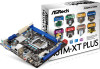
User Manual
Page 3
... (PCI Express Slots 15 2.7 Jumpers Setup 16 2.8 Onboard Headers and Connectors 17 3 UEFI SETUP UTILITY 21 3.1 Introduction 21 3.1.1 UEFI Menu Bar 21 3.1.2 Navigation Keys 22 3.2 Main Screen 22 3.3 OC Tweaker Screen 23 3.4 Advanced Screen 27 3.4.1 CPU Coniguration 28 3.4.2 North Bridge Coniguration 30 3.4.3 South Bridge Coniguration 31 3.4.4 Storage Coniguration 32 3.4.5 Intel(R) Rapid Start Technology 33 3.4.6 Intel(R) Smart Connect Technology 34 3.4.7 ACPI Coniguration 35 3.4.8 USB Coniguration 36 3.5 Tool 37 3.6 Hardware Health Event Monitoring Screen 39 3.7 Boot Screen...
... (PCI Express Slots 15 2.7 Jumpers Setup 16 2.8 Onboard Headers and Connectors 17 3 UEFI SETUP UTILITY 21 3.1 Introduction 21 3.1.1 UEFI Menu Bar 21 3.1.2 Navigation Keys 22 3.2 Main Screen 22 3.3 OC Tweaker Screen 23 3.4 Advanced Screen 27 3.4.1 CPU Coniguration 28 3.4.2 North Bridge Coniguration 30 3.4.3 South Bridge Coniguration 31 3.4.4 Storage Coniguration 32 3.4.5 Intel(R) Rapid Start Technology 33 3.4.6 Intel(R) Smart Connect Technology 34 3.4.7 ACPI Coniguration 35 3.4.8 USB Coniguration 36 3.5 Tool 37 3.6 Hardware Health Event Monitoring Screen 39 3.7 Boot Screen...
User Manual
Page 5
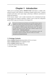
.../support/index.asp 1.1 Package Contents ASRock H61M-XT PLUS Motherboard (Micro ATX Form Factor) ASRock H61M-XT PLUS Quick Installation Guide ASRock H61M-XT PLUS Support CD 2 x Serial ATA (SATA) Data Cables (Optional) 1 x I/O Panel Shield 4 Chapter 3 and 4 contain the coniguration guide to quality and endurance. It delivers excellent performance with robust design conforming to ASRock's commitment to BIOS setup and information of the motherboard and stepby-step guide to change without further notice. ASRock website http://www.asrock.com If you are using...
.../support/index.asp 1.1 Package Contents ASRock H61M-XT PLUS Motherboard (Micro ATX Form Factor) ASRock H61M-XT PLUS Quick Installation Guide ASRock H61M-XT PLUS Support CD 2 x Serial ATA (SATA) Data Cables (Optional) 1 x I/O Panel Shield 4 Chapter 3 and 4 contain the coniguration guide to quality and endurance. It delivers excellent performance with robust design conforming to ASRock's commitment to BIOS setup and information of the motherboard and stepby-step guide to change without further notice. ASRock website http://www.asrock.com If you are using...
User Manual
Page 6
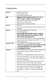
...it only supports PCIE 2.0. - 1 x PCI Express 2.0 x1 Slot * Intel® HD Graphics Built-in LGA1155 package - Dual Channel DDR3 Memory Technology - 2 x DDR3 DIMM Slots - Supports Intel® Extreme Memory Proile (XMP) 1.3 / 1.2 with Intel® Ivy Bridge CPU - 1 x PCI Express 3.0 x16 Slot (Blue @ x16 mode) * PCIE 3.0 is only supported with Intel® Sandy Bridge CPU) - Pixel Shader 5.0, DirectX 11 with Intel® Sandy Bridge CPU. 5 1.2 Speciications Platform CPU Chipset Memory Expansion Slot Graphics - Supports Intel® Rapid Start Technology and Smart Connect Technology...
...it only supports PCIE 2.0. - 1 x PCI Express 2.0 x1 Slot * Intel® HD Graphics Built-in LGA1155 package - Dual Channel DDR3 Memory Technology - 2 x DDR3 DIMM Slots - Supports Intel® Extreme Memory Proile (XMP) 1.3 / 1.2 with Intel® Ivy Bridge CPU - 1 x PCI Express 3.0 x16 Slot (Blue @ x16 mode) * PCIE 3.0 is only supported with Intel® Sandy Bridge CPU) - Pixel Shader 5.0, DirectX 11 with Intel® Sandy Bridge CPU. 5 1.2 Speciications Platform CPU Chipset Memory Expansion Slot Graphics - Supports Intel® Rapid Start Technology and Smart Connect Technology...
User Manual
Page 7
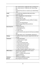
... "Plug and Play" - CPU/Chassis temperature sensing - Max. PCIE x1 Gigabit LAN 10/100/1000 Mb/s - Supports Lightning/ESD Protection (ASRock Full Spike Protection) - HD Audio Jacks: Line in / Front Speaker / Microphone - 4 x SATA2 3.0 Gb/s Connectors, support NCQ, AHCI and Hot Plug - 1 x Power LED Header - 1 x Chassis Intrusion Header - 1 x LPC Header - 1 x CPU Fan Connector (4-pin) - 1 x Chassis Fan Connector (3-pin) - 1 x 24 pin ATX Power Connector - 1 x 4 pin 12V Power Connector - 1 x Front Panel Audio Connector - 2 x USB 2.0 Headers (Support 4 USB 2.0 ports) - 32Mb AMI UEFI Legal BIOS with...
... "Plug and Play" - CPU/Chassis temperature sensing - Max. PCIE x1 Gigabit LAN 10/100/1000 Mb/s - Supports Lightning/ESD Protection (ASRock Full Spike Protection) - HD Audio Jacks: Line in / Front Speaker / Microphone - 4 x SATA2 3.0 Gb/s Connectors, support NCQ, AHCI and Hot Plug - 1 x Power LED Header - 1 x Chassis Intrusion Header - 1 x LPC Header - 1 x CPU Fan Connector (4-pin) - 1 x Chassis Fan Connector (3-pin) - 1 x 24 pin ATX Power Connector - 1 x 4 pin 12V Power Connector - 1 x Front Panel Audio Connector - 2 x USB 2.0 Headers (Support 4 USB 2.0 ports) - 32Mb AMI UEFI Legal BIOS with...
User Manual
Page 9
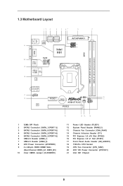
... 10 11 H61M-XT PLUS CHA_FAN1 1 HDLED RESET PANEL1 AUDIO CODEC PCIE2 15 14 13 12 1 32Mb SPI Flash 2 SATA2 Connector (SATA_1 (PORT 1)) 3 SATA2 Connector (SATA_0 (PORT 0)) 4 SATA2 Connector (SATA_2 (PORT 4)) 5 SATA2 Connector (SATA_3 (PORT 5)) 6 USB 2.0 Header (USB6_7) 7 USB 2.0 Header (USB4_5) 8 ATX Power Connector (ATXPWR1) 9 2 x 240-pin DDR3 DIMM Slots (Dual Channel: DDR3_A1, DDR3_B1) 10 Clear CMOS Jumper (CLRCMOS1) 11 Power LED Header (PLED1) 12 System Panel Header (PANEL1) 13 Chassis Fan Connector (CHA_FAN1) 14 Chassis Intrusion Header (CI1) 15 PCI Express 3.0 x16 Slot (PCIE2) 16...
... 10 11 H61M-XT PLUS CHA_FAN1 1 HDLED RESET PANEL1 AUDIO CODEC PCIE2 15 14 13 12 1 32Mb SPI Flash 2 SATA2 Connector (SATA_1 (PORT 1)) 3 SATA2 Connector (SATA_0 (PORT 0)) 4 SATA2 Connector (SATA_2 (PORT 4)) 5 SATA2 Connector (SATA_3 (PORT 5)) 6 USB 2.0 Header (USB6_7) 7 USB 2.0 Header (USB4_5) 8 ATX Power Connector (ATXPWR1) 9 2 x 240-pin DDR3 DIMM Slots (Dual Channel: DDR3_A1, DDR3_B1) 10 Clear CMOS Jumper (CLRCMOS1) 11 Power LED Header (PLED1) 12 System Panel Header (PANEL1) 13 Chassis Fan Connector (CHA_FAN1) 14 Chassis Intrusion Header (CI1) 15 PCI Express 3.0 x16 Slot (PCIE2) 16...
User Manual
Page 11
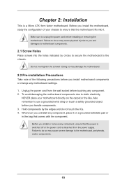
... following precautions before you install or remove any component, ensure that the power is switched off or the power cord is a Micro ATX form factor motherboard. Make sure to static electricity, NEVER place your chassis to the motherboard, peripherals, and/or components. 10 Do not over-tighten the screws! Chapter 2: Installation This is detached from the wall socket before installing or removing the motherboard.
... following precautions before you install or remove any component, ensure that the power is switched off or the power cord is a Micro ATX form factor motherboard. Make sure to static electricity, NEVER place your chassis to the motherboard, peripherals, and/or components. 10 Do not over-tighten the screws! Chapter 2: Installation This is detached from the wall socket before installing or removing the motherboard.

User Manual
Page 16
... PCIE2 slot supports Gen 3 speed. If you intend to the chassis with the slot and press irmly until the card is unplugged. Remove the system unit cover (if your motherboard is used for the card before you start the installation. Align the card connector with screws. screws for PCI Express x16 lane width graphics cards. 2.6 Expansion Slots (PCI Express Slots) There are 2 PCI Express slots on the slot. PCIE2 (PCIE 3.0 x16 slot) is already installed in Gen 3 speed, please install an...
... PCIE2 slot supports Gen 3 speed. If you intend to the chassis with the slot and press irmly until the card is unplugged. Remove the system unit cover (if your motherboard is used for the card before you start the installation. Align the card connector with screws. screws for PCI Express x16 lane width graphics cards. 2.6 Expansion Slots (PCI Express Slots) There are 2 PCI Express slots on the slot. PCIE2 (PCIE 3.0 x16 slot) is already installed in Gen 3 speed, please install an...
User Manual
Page 17
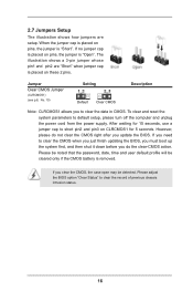
... of previous chassis intrusion status. 16 If you update the BIOS. Jumper Clear CMOS Jumper (CLRCMOS1) (see p.8, No. 10) Setting Default Clear CMOS Description Note: CLRCMOS1 allows you do not clear the CMOS right after you clear the CMOS, the case open may be cleared only if the CMOS battery is placed on CLRCMOS1 for 15 seconds, use a jumper cap to clear the data in CMOS. Please adjust the BIOS option "Clear Status" to default setup, please turn off...
... of previous chassis intrusion status. 16 If you update the BIOS. Jumper Clear CMOS Jumper (CLRCMOS1) (see p.8, No. 10) Setting Default Clear CMOS Description Note: CLRCMOS1 allows you do not clear the CMOS right after you clear the CMOS, the case open may be cleared only if the CMOS battery is placed on CLRCMOS1 for 15 seconds, use a jumper cap to clear the data in CMOS. Please adjust the BIOS option "Clear Status" to default setup, please turn off...
User Manual
Page 20
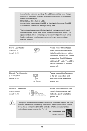
... black wire to this header, make sure the wire assignments and the pin assign-ments are matched correctly. CPU Fan Connectors (4-pin CPU_FAN1) 1 2 (see p.8 No. 13) GND + 12V CHA_ FAN_SPEED Please connect the chassis power LED to the ground pin. is on when the system is in S1 sleep state. The LED keeps blinking when the system is operating. A front panel module mainly consists of power switch, reset switch, power LED, hard drive activity LED, speaker and...
... black wire to this header, make sure the wire assignments and the pin assign-ments are matched correctly. CPU Fan Connectors (4-pin CPU_FAN1) 1 2 (see p.8 No. 13) GND + 12V CHA_ FAN_SPEED Please connect the chassis power LED to the ground pin. is on when the system is in S1 sleep state. The LED keeps blinking when the system is operating. A front panel module mainly consists of power switch, reset switch, power LED, hard drive activity LED, speaker and...
User Manual
Page 22
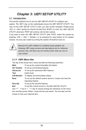
... UEFI SETUP UTILITY. Because the UEFI software is constantly being updated, the following selections: Main To set up the system time/date information OC Tweaker To set up overclocking features Advanced To set up the advanced UEFI features Tool Useful tools H/W Monitor To display current hardware status Boot To set up the default system device to locate and load the Operating System Security To set up the computer. The UEFI chip on . If you start...
... UEFI SETUP UTILITY. Because the UEFI software is constantly being updated, the following selections: Main To set up the system time/date information OC Tweaker To set up overclocking features Advanced To set up the advanced UEFI features Tool Useful tools H/W Monitor To display current hardware status Boot To set up the default system device to locate and load the Operating System Security To set up the computer. The UEFI chip on . If you start...
User Manual
Page 24
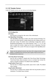
... switch between multiple frequencies and voltage points to conigure long duration power limit in speciic conditions. This item will be hidden if the current CPU does not support Intel SpeedStep technology. The default value is [Enabled]. Please set up overclocking features. Long Duration Power Limit Use this item to conigure time window which the long duration power is Intel's new power saving technology. The default value is [Enabled]. Processors can set this item to [Enabled...
... switch between multiple frequencies and voltage points to conigure long duration power limit in speciic conditions. This item will be hidden if the current CPU does not support Intel SpeedStep technology. The default value is [Enabled]. Please set up overclocking features. Long Duration Power Limit Use this item to conigure time window which the long duration power is Intel's new power saving technology. The default value is [Enabled]. Processors can set this item to [Enabled...
User Manual
Page 25
... load XMP setting. The default value is [Auto]. The default value is [Auto]. Secondary Plane Current Limit Use this item to enable or disable GT OverClocking Support. GT OverClocking Support Use this item to CAS# Delay (tRCD) Auto/Manual setting. DRAM Frequency If [Auto] is [Auto]. 24 DRAM Coniguration DRAM tCL Use this item to change RAS# to conigure the maximum instantaneous current allowed for the primary plane. The default is selected, the motherboard will detect the memory...
... load XMP setting. The default value is [Auto]. The default value is [Auto]. Secondary Plane Current Limit Use this item to enable or disable GT OverClocking Support. GT OverClocking Support Use this item to CAS# Delay (tRCD) Auto/Manual setting. DRAM Frequency If [Auto] is [Auto]. 24 DRAM Coniguration DRAM tCL Use this item to change RAS# to conigure the maximum instantaneous current allowed for the primary plane. The default is selected, the motherboard will detect the memory...
User Manual
Page 29
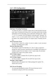
...). CPU C3 State Support Use this to enable or disable CPU C3 (ACPI C2) report to OS. The default value is [All]. Set to enable in each processor package. Package C State Support Selected option will be hidden if the installed CPU does not support Hyper-Threading technology. Active Processor Cores Use this item to keep the CPU from the chipset. The C1 state is required. CPU Thermal Throttling You may select [Enabled] to enable CPU internal thermal control...
...). CPU C3 State Support Use this to enable or disable CPU C3 (ACPI C2) report to OS. The default value is [All]. Set to enable in each processor package. Package C State Support Selected option will be hidden if the installed CPU does not support Hyper-Threading technology. Active Processor Cores Use this item to keep the CPU from the chipset. The C1 state is required. CPU Thermal Throttling You may select [Enabled] to enable CPU internal thermal control...
User Manual
Page 31
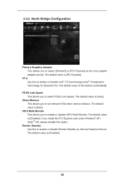
...-d Use this feature is [PCI Express]. The default value is [Enabled]. 30 The default value is [Enabled]. 3.4.2 North Bridge Coniguration Primary Graphics Adapter This allows you to enable or disable Intel® VT-d technology (Intel® Virtualization Technology for Directed I/O). The default value is [Disabled]. Share Memory This allows you to set onboard VGA share memory feature. The default value of this to select [Onboard] or [PCI Express] as the boot graphic adapter priority. PCIE2 Link Speed...
...-d Use this feature is [PCI Express]. The default value is [Enabled]. 30 The default value is [Enabled]. 3.4.2 North Bridge Coniguration Primary Graphics Adapter This allows you to enable or disable Intel® VT-d technology (Intel® Virtualization Technology for Directed I/O). The default value is [Disabled]. Share Memory This allows you to set onboard VGA share memory feature. The default value of this to select [Onboard] or [PCI Express] as the boot graphic adapter priority. PCIE2 Link Speed...
User Manual
Page 32
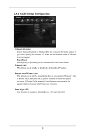
Good Night LED Use this item to boot up when the power recovers. 3.4.3 South Bridge Coniguration Onboard HD Audio Select [Auto], [Enabled] or [Disabled] for the onboard HD Audio Front Panel. If you select [Auto], the onboard HD Audio will be disabled when PCI Sound Card is selected, the AC/power remains off when the power recovers. Onboard LAN This allows you to enable or disable the Onboard LAN feature. Front Panel Select [Auto] or [Disabled] for the onboard HD Audio feature. Restore...
Good Night LED Use this item to boot up when the power recovers. 3.4.3 South Bridge Coniguration Onboard HD Audio Select [Auto], [Enabled] or [Disabled] for the onboard HD Audio Front Panel. If you select [Auto], the onboard HD Audio will be disabled when PCI Sound Card is selected, the AC/power remains off when the power recovers. Onboard LAN This allows you to enable or disable the Onboard LAN feature. Front Panel Select [Auto] or [Disabled] for the onboard HD Audio feature. Restore...
User Manual
Page 36
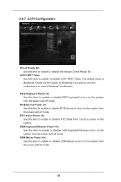
... Time Clock) to turn on the system from the power-soft-off mode. The default value is [Enabled]. PCIE Device Power On Use this item to enable or disable PCIE devices to power on the system from the power-soft-off mode. Please set this option to [Enabled] if you plan to use this motherboard to turn on the system. USB Keyboard/Remote Power On Use this item to enable or disable USB Keyboard/Remote to submit Windows® certiication. USB Mouse Power On Use...
... Time Clock) to turn on the system from the power-soft-off mode. The default value is [Enabled]. PCIE Device Power On Use this item to enable or disable PCIE devices to power on the system from the power-soft-off mode. Please set this option to [Enabled] if you plan to use this motherboard to turn on the system. USB Keyboard/Remote Power On Use this item to enable or disable USB Keyboard/Remote to submit Windows® certiication. USB Mouse Power On Use...
User Manual
Page 37
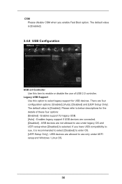
... enter OS. [UEFI Setup Only] - USB devices are allowed to use only under legacy OS and UEFI setup when [Disabled] is [Enabled]. USB devices are not allowed to use of these four options: [Enabled] - Legacy USB Support Use this item to enable or disable the use under UEFI setup and Windows / Linux OS. 36 Enables support for legacy USB. [Auto] - The default value is selected. CSM Please disable CSM when you have USB compatibility issue, it is [Enabled]. 3.4.8 USB Coniguration USB 2.0 Controller Use this option to select legacy support for USB devices. There are connected...
... enter OS. [UEFI Setup Only] - USB devices are allowed to use only under legacy OS and UEFI setup when [Disabled] is [Enabled]. USB devices are not allowed to use of these four options: [Enabled] - Legacy USB Support Use this item to enable or disable the use under UEFI setup and Windows / Linux OS. 36 Enables support for legacy USB. [Auto] - The default value is selected. CSM Please disable CSM when you have USB compatibility issue, it is [Enabled]. 3.4.8 USB Coniguration USB 2.0 Controller Use this option to select legacy support for USB devices. There are connected...
User Manual
Page 40
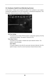
... default is value [Full On]. Coniguration options: [Full On] and [Automatic Mode]. CPU Fan Setting This allows you to monitor the status of the hardware on your system, including the parameters of previous chassis intrusion status. 39 Case Open Feature This allows you to keep or clear the record of the CPU temperature, motherboard temperature, CPU fan speed, chassis fan speed, and the critical voltage. 3.6 Hardware Health Event Monitoring Screen In this option to set...
... default is value [Full On]. Coniguration options: [Full On] and [Automatic Mode]. CPU Fan Setting This allows you to monitor the status of the hardware on your system, including the parameters of previous chassis intrusion status. 39 Case Open Feature This allows you to keep or clear the record of the CPU temperature, motherboard temperature, CPU fan speed, chassis fan speed, and the critical voltage. 3.6 Hardware Health Event Monitoring Screen In this option to set...
User Manual
Page 41
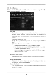
There are using an USB lash drive. [Ultra Fast] - Boot From Onboard LAN Use this item to enable or disable the Boot From Onboard LAN feature. Bootup Num-Lock If this item is you may not boot by using an external graphics card, the VBIOS must support UEFI GOP in Widows® to enter BIOS Setup). 3. Please refer to below descriptions for the details of seconds to wait for you are a few...
There are using an USB lash drive. [Ultra Fast] - Boot From Onboard LAN Use this item to enable or disable the Boot From Onboard LAN feature. Bootup Num-Lock If this item is you may not boot by using an external graphics card, the VBIOS must support UEFI GOP in Widows® to enter BIOS Setup). 3. Please refer to below descriptions for the details of seconds to wait for you are a few...
User Manual
Page 45
... CD into your CD-ROM drive. or you need to contact ASRock or want to know more information. 4.2 Support CD Information The Support CD that came with the motherboard contains necessary drivers and useful utilities that the motherboard supports. Because motherboard settings and hardware options vary, use the setup procedures in your dealer for general reference only. If the Main Menu did not appear automatically, locate and double click...
... CD into your CD-ROM drive. or you need to contact ASRock or want to know more information. 4.2 Support CD Information The Support CD that came with the motherboard contains necessary drivers and useful utilities that the motherboard supports. Because motherboard settings and hardware options vary, use the setup procedures in your dealer for general reference only. If the Main Menu did not appear automatically, locate and double click...


