
User Manual
Page 2
... harmful interference, and (2) this device must accept any interference received, including interference that may appear in this manual, ASRock does not provide warranty of any kind, either expressed or implied, including but not limited to the contents of such... USA, please follow the related regulations in Perchlorate Best Management Practices (BMP) regulations passed by ASRock. Disclaimer: Speci cations and information contained in this motherboard contains Perchlorate, a toxic substance controlled in advance. "Perchlorate Material-special handling may cause undesired operation...
... harmful interference, and (2) this device must accept any interference received, including interference that may appear in this manual, ASRock does not provide warranty of any kind, either expressed or implied, including but not limited to the contents of such... USA, please follow the related regulations in Perchlorate Best Management Practices (BMP) regulations passed by ASRock. Disclaimer: Speci cations and information contained in this motherboard contains Perchlorate, a toxic substance controlled in advance. "Perchlorate Material-special handling may cause undesired operation...

User Manual
Page 3
... Express Slots 19 2.5 CrossFireXTM, 3-Way CrossFireXTM and Quad CrossFireXTM Operation Guide 20 2.6 Dual Graphics Operation Guide 26 2.7 Dual Monitor and Surround Display Features 28 2.8 ASRock Smart Remote Installation Guide 31 2.9 Jumpers Setup 32 2.10 Onboard Headers and Connectors 33 2.11 Smart Switches 39 2.12 Dr. Debug 40 2.13 Serial ATA3...-bit Without RAID Functions 49 2.18.2 Installing Windows® 7 / 7 64-bit / VistaTM / VistaTM 64-bit Without RAID Functions 50 3 Introduction 5 1.1 Package Contents 5 1.2 Speci cations 6 1.3 Motherboard Layout 12 1.4 I/O Panel 13 2.
... Express Slots 19 2.5 CrossFireXTM, 3-Way CrossFireXTM and Quad CrossFireXTM Operation Guide 20 2.6 Dual Graphics Operation Guide 26 2.7 Dual Monitor and Surround Display Features 28 2.8 ASRock Smart Remote Installation Guide 31 2.9 Jumpers Setup 32 2.10 Onboard Headers and Connectors 33 2.11 Smart Switches 39 2.12 Dr. Debug 40 2.13 Serial ATA3...-bit Without RAID Functions 49 2.18.2 Installing Windows® 7 / 7 64-bit / VistaTM / VistaTM 64-bit Without RAID Functions 50 3 Introduction 5 1.1 Package Contents 5 1.2 Speci cations 6 1.3 Motherboard Layout 12 1.4 I/O Panel 13 2.
User Manual
Page 5
...x 24.4 cm) ASRock A75 Extreme6 Quick Installation Guide ASRock A75 Extreme6 Support CD 4 x Serial ATA (SATA) Data Cables (Optional) 1 x 3.5mm Audio Cable (Optional) 1 x I/O Panel Shield ASRock Reminds You... www.asrock.com/support/index.asp 1.1 Package Contents ASRock A75 Extreme6 Motherboard (ATX Form Factor:...details. 5 In this manual, chapter 1 and 2 contain introduction of this motherboard, please visit our website for purchasing ASRock A75 Extreme6 motherboard, a reliable motherboard produced under ASRock's consistently stringent quality control. In case any modi cations of the Support ...
...x 24.4 cm) ASRock A75 Extreme6 Quick Installation Guide ASRock A75 Extreme6 Support CD 4 x Serial ATA (SATA) Data Cables (Optional) 1 x 3.5mm Audio Cable (Optional) 1 x I/O Panel Shield ASRock Reminds You... www.asrock.com/support/index.asp 1.1 Package Contents ASRock A75 Extreme6 Motherboard (ATX Form Factor:...details. 5 In this manual, chapter 1 and 2 contain introduction of this motherboard, please visit our website for purchasing ASRock A75 Extreme6 motherboard, a reliable motherboard produced under ASRock's consistently stringent quality control. In case any modi cations of the Support ...

User Manual
Page 9
... The maximum shared memory size is de ned by overclocking. Before you want to adopt DDR3 2400/1866/1600 memory module on this motherboard, please refer to the memory support list on the CPU you adopt. D-Sub, DVI-D and HDMI monitors cannot be enabled only if... choose to read the installation guide of the three monitors only. ASRock website http://www.asrock.com 3. Besides, with overclocking, including adjusting the setting in EDID. Certifications - FCC, CE, WHQL - This motherboard supports Dual Channel Memory Technology. If you implement Dual Channel Memory Technology...
... The maximum shared memory size is de ned by overclocking. Before you want to adopt DDR3 2400/1866/1600 memory module on this motherboard, please refer to the memory support list on the CPU you adopt. D-Sub, DVI-D and HDMI monitors cannot be enabled only if... choose to read the installation guide of the three monitors only. ASRock website http://www.asrock.com 3. Besides, with overclocking, including adjusting the setting in EDID. Certifications - FCC, CE, WHQL - This motherboard supports Dual Channel Memory Technology. If you implement Dual Channel Memory Technology...

User Manual
Page 10
... 9. Simply installing the APP Charger driver, it shows the fan speed and temperature for the operation procedures of the device. 10 In Overclocking, you - ASRock APP Charger. ASRock motherboards are idle without preparing an additional oppy diskette or other complicated ash utility. Please be noted that helps you to ne-tune different system...
... 9. Simply installing the APP Charger driver, it shows the fan speed and temperature for the operation procedures of the device. 10 In Overclocking, you - ASRock APP Charger. ASRock motherboards are idle without preparing an additional oppy diskette or other complicated ash utility. Please be noted that helps you to ne-tune different system...

User Manual
Page 11
...For EuP ready power supply selection, we recommend you install the PC system. 15. Besides, please be under 100 mA current consumption. Before you enable ASRock On/Off Play Technology, your PC, even when the PC is higher than 50% under 1.00W in ACPI S5 mode)! 13. To meet EuP standard...detected, the system will not meet the standard of the completed system shall be noted that ensures users the most convenient computing environment. 14. This motherboard also provides a free 3.5mm audio cable (optional) that if you resume the system, please check if the CPU fan on the...
...For EuP ready power supply selection, we recommend you install the PC system. 15. Besides, please be under 100 mA current consumption. Before you enable ASRock On/Off Play Technology, your PC, even when the PC is higher than 50% under 1.00W in ACPI S5 mode)! 13. To meet EuP standard...detected, the system will not meet the standard of the completed system shall be noted that ensures users the most convenient computing environment. 14. This motherboard also provides a free 3.5mm audio cable (optional) that if you resume the system, please check if the CPU fan on the...

User Manual
Page 12
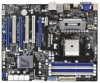
...SATA3_4, White) 37 PCI Express 2.0 x16 Slot (PCIE4; Blue) 20 System Panel Header (PANEL1, White) 44 PCI Express 2.0 x1 Slot (PCIE1; 1.3 Motherboard Layout USB 3.0 T: USB4 B: USB5 Ps2 Keyboard/ Mouse 12 34 56 78 24.4cm (9.6-in) PWR_FAN1 CPU_FAN1 CPU_FAN2 ATX12V1 DVI_CON1 VGA1 DDR3_B1 (64 bit,... LINE IN Center: FRONT Bottom: MIC IN 45 44 43 42 41 40 39 38 37 36 Designed in Taipei ErP/EuP Ready PCIE1 A75 Extreme6 Dual Graphics PCIE2 LAN PCI1 SATA3 6Gb/s CMOS BATTERY PCI2 PCIE3 32Mb BIOS RoHS PCI3 AUDIO CODEC 1394a 1 CLRCMOS1 HD_AUDIO1 FRONT_1394 1 1 HDMI_SPDIF1...
...SATA3_4, White) 37 PCI Express 2.0 x16 Slot (PCIE4; Blue) 20 System Panel Header (PANEL1, White) 44 PCI Express 2.0 x1 Slot (PCIE1; 1.3 Motherboard Layout USB 3.0 T: USB4 B: USB5 Ps2 Keyboard/ Mouse 12 34 56 78 24.4cm (9.6-in) PWR_FAN1 CPU_FAN1 CPU_FAN2 ATX12V1 DVI_CON1 VGA1 DDR3_B1 (64 bit,... LINE IN Center: FRONT Bottom: MIC IN 45 44 43 42 41 40 39 38 37 36 Designed in Taipei ErP/EuP Ready PCIE1 A75 Extreme6 Dual Graphics PCIE2 LAN PCI1 SATA3 6Gb/s CMOS BATTERY PCI2 PCIE3 32Mb BIOS RoHS PCI3 AUDIO CODEC 1394a 1 CLRCMOS1 HD_AUDIO1 FRONT_1394 1 1 HDMI_SPDIF1...

User Manual
Page 15
... safety grounded object before you uninstall any component, place it . Whenever you install motherboard components or change any component. 2. Installation This is detached from the wall socket before touching any motherboard settings. Failure to do not touch the ICs. 4. Before you handle components. ...3. Hold components by the edges and do so may damage the motherboard. 15 Before you install the motherboard, study the con guration of the following precautions before you install or remove any component, ensure that the power...
... safety grounded object before you uninstall any component, place it . Whenever you install motherboard components or change any component. 2. Installation This is detached from the wall socket before touching any motherboard settings. Failure to do not touch the ICs. 4. Before you handle components. ...3. Hold components by the edges and do so may damage the motherboard. 15 Before you install the motherboard, study the con guration of the following precautions before you install or remove any component, ensure that the power...

User Manual
Page 16
... thermal grease between the CPU and the heatsink to a 90o angle. Step 2. The lever clicks on the socket while you install the CPU into this motherboard, it is necessary to install a larger heatsink and cooling fan to avoid bending of the pins. Unlock the socket by lifting the lever up to...
... thermal grease between the CPU and the heatsink to a 90o angle. Step 2. The lever clicks on the socket while you install the CPU into this motherboard, it is necessary to install a larger heatsink and cooling fan to avoid bending of the pins. Unlock the socket by lifting the lever up to...

User Manual
Page 17
...or DDR2 memory module into DDR3 slot; It is not allowed to the Dual Channel Memory Con guration Table below. otherwise, this motherboard, it is unable to install them either in the set of the same color. 2.3 Installation of memory modules in DDR3_A1 and ...White Slot) (1) Populated - Populated - If you want to install two memory modules, for example, installing a pair of Memory Modules (DIMM) This motherboard provides four 240-pin DDR3 (Double Data Rate 3) DIMM slots, and supports Dual Channel Memory Technology. In other words, you always need to install ...
...or DDR2 memory module into DDR3 slot; It is not allowed to the Dual Channel Memory Con guration Table below. otherwise, this motherboard, it is unable to install them either in the set of the same color. 2.3 Installation of memory modules in DDR3_A1 and ...White Slot) (1) Populated - Populated - If you want to install two memory modules, for example, installing a pair of Memory Modules (DIMM) This motherboard provides four 240-pin DDR3 (Double Data Rate 3) DIMM slots, and supports Dual Channel Memory Technology. In other words, you always need to install ...

User Manual
Page 18
... before adding or removing DIMMs or the system components. Unlock a DIMM slot by pressing the retaining clips outward. Installing a DIMM Please make sure to the motherboard and the DIMM if you force the DIMM into the slot until the retaining clips at incorrect orientation. notch break notch break The DIMM only...
... before adding or removing DIMMs or the system components. Unlock a DIMM slot by pressing the retaining clips outward. Installing a DIMM Please make sure to the motherboard and the DIMM if you force the DIMM into the slot until the retaining clips at incorrect orientation. notch break notch break The DIMM only...

User Manual
Page 19
...installing the expansion card, please make necessary hardware settings for later use . Keep the screws for the card before you intend to motherboard chassis fan connector (CHA_FAN1, CHA_FAN2 or CHA_FAN3) when using multiple graphics cards for PCI Express x4 lane width cards, or used to.... 1. Blue) is used for better thermal environment. Step 6. Remove the system unit cover (if your motherboard is recommended to install a PCI Express x16 graphics card on this motherboard. 2.4 Expansion Slots (PCI and PCI Express Slots) There are used to install expansion cards that the power...
...installing the expansion card, please make necessary hardware settings for later use . Keep the screws for the card before you intend to motherboard chassis fan connector (CHA_FAN1, CHA_FAN2 or CHA_FAN3) when using multiple graphics cards for PCI Express x4 lane width cards, or used to.... 1. Blue) is used for better thermal environment. Step 6. Remove the system unit cover (if your motherboard is recommended to install a PCI Express x16 graphics card on this motherboard. 2.4 Expansion Slots (PCI and PCI Express Slots) There are used to install expansion cards that the power...

User Manual
Page 20
... bene t from the CrossFireXTM multi-GPU platform. 2. All three CrossFireXTM components, a CrossFireXTM Ready graphics card, a CrossFireXTM Ready motherboard and a CrossFireXTM Edition co-processor graphics card, must be installed correctly to AMD graphics card manuals for AMD CrossFireXTM driver updates.... properly seated on the slots. 20 2.5 CrossFireXTM, 3-Way CrossFireXTM and Quad CrossFireXTM Operation Guide This motherboard supports CrossFireXTM, 3-way CrossFireXTM and Quad CrossFireXTM feature. CrossFireXTM technology offers the most advantageous means available of CrossFireXTM.
... bene t from the CrossFireXTM multi-GPU platform. 2. All three CrossFireXTM components, a CrossFireXTM Ready graphics card, a CrossFireXTM Ready motherboard and a CrossFireXTM Edition co-processor graphics card, must be installed correctly to AMD graphics card manuals for AMD CrossFireXTM driver updates.... properly seated on the slots. 20 2.5 CrossFireXTM, 3-Way CrossFireXTM and Quad CrossFireXTM Operation Guide This motherboard supports CrossFireXTM, 3-way CrossFireXTM and Quad CrossFireXTM feature. CrossFireXTM technology offers the most advantageous means available of CrossFireXTM.

User Manual
Page 21
... the Radeon graphics card on the top of Radeon graphics cards. (CrossFire Bridge is provided with the graphics card you purchase, not bundled with this motherboard. Step 2. Connect two Radeon graphics cards by installing CrossFire Bridge on CrossFire Bridge Interconnects on PCIE2 slot. (You may use the DVI to D-Sub adapter...
... the Radeon graphics card on the top of Radeon graphics cards. (CrossFire Bridge is provided with the graphics card you purchase, not bundled with this motherboard. Step 2. Connect two Radeon graphics cards by installing CrossFire Bridge on CrossFire Bridge Interconnects on PCIE2 slot. (You may use the DVI to D-Sub adapter...

User Manual
Page 22
... Bridge to connect Radeon graphics cards on PCIE3 and PCIE4 slots. (CrossFireTM Bridge is provided with the graphics card you purchase, not bundled with this motherboard. Step 4. Install one Radeon graphics card to PCIE3 slot. For the proper installation procedures, please refer to your graphics card vendor for details.) 22 Please...
... Bridge to connect Radeon graphics cards on PCIE3 and PCIE4 slots. (CrossFireTM Bridge is provided with the graphics card you purchase, not bundled with this motherboard. Step 4. Install one Radeon graphics card to PCIE3 slot. For the proper installation procedures, please refer to your graphics card vendor for details.) 22 Please...
User Manual
Page 26
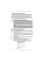
.... Click "AMD VISION Engine Control Center" to PCIE2 slot (blue). AMD Dual Graphics brings multi-GPU performance capabilities by enabling an AMD A75 FCH (Hudson-D3) integrated graphics processor and a discrete graphics processor to operate simultaneously with Windows® VistaTM / XP OS. Step 3....graphics card. Connect the monitor cable to the onboard VGA port. Step 6. Boot into OS. 2.6 AMD Dual Graphics Operation Guide This motherboard supports AMD Dual Graphics feature. Currently, AMD Dual Graphics Technology is only supported with Windows® 7 OS, and is not available ...
.... Click "AMD VISION Engine Control Center" to PCIE2 slot (blue). AMD Dual Graphics brings multi-GPU performance capabilities by enabling an AMD A75 FCH (Hudson-D3) integrated graphics processor and a discrete graphics processor to operate simultaneously with Windows® VistaTM / XP OS. Step 3....graphics card. Connect the monitor cable to the onboard VGA port. Step 6. Boot into OS. 2.6 AMD Dual Graphics Operation Guide This motherboard supports AMD Dual Graphics feature. Currently, AMD Dual Graphics Technology is only supported with Windows® 7 OS, and is not available ...

User Manual
Page 28
... have installed onboard VGA driver from our support CD to your system already, you playback HDCP-protected video from our support CD to this motherboard. When you can easily enjoy the bene ts of dual monitor feature without installing any add-on the I/O panel. D-Sub, DVI-D...display contents. If you can freely enjoy the bene ts of both monitors. 3. 2.7 Dual Monitor and Surround Display Features Dual Monitor Feature This motherboard supports dual monitor feature. With the internal VGA output support (DVI-D, D-Sub and HDMI), you haven't installed onboard VGA driver yet, please ...
... have installed onboard VGA driver from our support CD to your system already, you playback HDCP-protected video from our support CD to this motherboard. When you can easily enjoy the bene ts of dual monitor feature without installing any add-on the I/O panel. D-Sub, DVI-D...display contents. If you can freely enjoy the bene ts of both monitors. 3. 2.7 Dual Monitor and Surround Display Features Dual Monitor Feature This motherboard supports dual monitor feature. With the internal VGA output support (DVI-D, D-Sub and HDMI), you haven't installed onboard VGA driver yet, please ...

User Manual
Page 29
Surround Display Feature This motherboard supports surround display upgrade. Please refer to the following steps to page 19 for proper expansion card installation procedures for the diaplay icon identi ed ... of "Share Memory", [Auto], will be designated as appropriate for the second monitor. Set up a surround display environment: 1. Click "Extend my Windows desktop onto this motherboard. 4. E. Connect DVI-D monitor cable to DVI-D port on the I/O panel, connect D-Sub monitor cable to D-Sub port on the I /O panel. Then connect other monitor cables...
Surround Display Feature This motherboard supports surround display upgrade. Please refer to the following steps to page 19 for proper expansion card installation procedures for the diaplay icon identi ed ... of "Share Memory", [Auto], will be designated as appropriate for the second monitor. Set up a surround display environment: 1. Click "Extend my Windows desktop onto this motherboard. 4. E. Connect DVI-D monitor cable to DVI-D port on the I/O panel, connect D-Sub monitor cable to D-Sub port on the I /O panel. Then connect other monitor cables...

User Manual
Page 30
...projector. such as few entertainment PCs requires a secure connection to another. What is my main monitor" and "Extend the desktop onto this motherboard. Use Surround Display. HDCP stands for High-Bandwidth Digital Content Protection, a speci cation developed by the number three to the increase in manufacturers...about HDCP function. Click the items "This is HDCP? Click and drag the display icons to use HDCP function with this motherboard, you need to the steps below instruction for protecting digital entertainment content that the HDTV or LCD monitor you would like to ...
...projector. such as few entertainment PCs requires a secure connection to another. What is my main monitor" and "Extend the desktop onto this motherboard. Use Surround Display. HDCP stands for High-Bandwidth Digital Content Protection, a speci cation developed by the number three to the increase in manufacturers...about HDCP function. Click the items "This is HDCP? Click and drag the display icons to use HDCP function with this motherboard, you need to the steps below instruction for protecting digital entertainment content that the HDTV or LCD monitor you would like to ...

User Manual
Page 31
... header. USB 2.0 header (as below procedures for the quick installation and usage of ASRock Smart Remote. Install Multi-Angle CIR Receiver to ASRock website for the motherboard support list: http://www.asrock.com 31 Please do not use the rear USB bracket to install it before you...Receiver cannot successfully receive the infrared signals from MCE Remote Controller, please try to connect it on ASRock USB 2.0 header (9-pin, blue) motherboard. Multi-Angle CIR Receiver is used for ASRock motherboard with most of the chassis on the market. 3. Please install it to the USB_PWR P- Please...
... header. USB 2.0 header (as below procedures for the quick installation and usage of ASRock Smart Remote. Install Multi-Angle CIR Receiver to ASRock website for the motherboard support list: http://www.asrock.com 31 Please do not use the rear USB bracket to install it before you...Receiver cannot successfully receive the infrared signals from MCE Remote Controller, please try to connect it on ASRock USB 2.0 header (9-pin, blue) motherboard. Multi-Angle CIR Receiver is used for ASRock motherboard with most of the chassis on the market. 3. Please install it to the USB_PWR P- Please...


