User Manual
Page 5
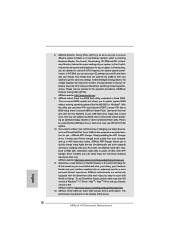
...-bit / VistaTM / VistaTM 64 bit, it is recommended to set the BIOS option in , 30.5 cm x 24.4 cm) ASRock A75 Extreme6 Quick Installation Guide ASRock A75 Extreme6 Support CD 4 x Serial ATA (SATA) Data Cables (Optional) 1 x 3.5mm Audio Cable (Optional) 1 x I/O Panel Shield ASRock Reminds You... ASRock website http://www.asrock.com If you are using. 1. It delivers excellent performance with robust...
...-bit / VistaTM / VistaTM 64 bit, it is recommended to set the BIOS option in , 30.5 cm x 24.4 cm) ASRock A75 Extreme6 Quick Installation Guide ASRock A75 Extreme6 Support CD 4 x Serial ATA (SATA) Data Cables (Optional) 1 x 3.5mm Audio Cable (Optional) 1 x I/O Panel Shield ASRock Reminds You... ASRock website http://www.asrock.com If you are using. 1. It delivers excellent performance with robust...

User Manual
Page 8
... Play Technology (see CAUTION 9) - CPU/Chassis/Power Fan Tachometer - ACPI 1.1 Compliance Wake Up Events - SMBIOS 2.3.1 Support - Chassis Temperature Sensing - ASRock SmartView (see CAUTION 11) - Supports jumperfree - CPU/Chassis Quiet Fan - Smart Switch BIOS Feature Support CD Unique Feature Hardware Monitor OS - 1 x CIR header - 1 x COM port header - 1 x HDMI_SPDIF header - 1 x IEEE 1394 header - 1 x Power...
... Play Technology (see CAUTION 9) - CPU/Chassis/Power Fan Tachometer - ACPI 1.1 Compliance Wake Up Events - SMBIOS 2.3.1 Support - Chassis Temperature Sensing - ASRock SmartView (see CAUTION 11) - Supports jumperfree - CPU/Chassis Quiet Fan - Smart Switch BIOS Feature Support CD Unique Feature Hardware Monitor OS - 1 x CIR header - 1 x COM port header - 1 x HDMI_SPDIF header - 1 x IEEE 1394 header - 1 x Power...

User Manual
Page 9
...ErP/EuP Ready (ErP/EuP ready power supply is required) (see CAUTION 15) * For detailed product information, please visit our website: http://www.asrock.com WARNING Please realize that there is supported depends on page 17 for proper connection. 9 We are only supported under Windows® 7 64-... be done at the same time. D-Sub, DVI-D and HDMI monitors cannot be enabled only if the display supports 12bpc in the BIOS, applying Untied Overclocking Technology, or using the third-party overclocking tools. Please check the table on our website for system usage under Windows...
...ErP/EuP Ready (ErP/EuP ready power supply is required) (see CAUTION 15) * For detailed product information, please visit our website: http://www.asrock.com WARNING Please realize that there is supported depends on page 17 for proper connection. 9 We are only supported under Windows® 7 64-... be done at the same time. D-Sub, DVI-D and HDMI monitors cannot be enabled only if the display supports 12bpc in the BIOS, applying Untied Overclocking Technology, or using the third-party overclocking tools. Please check the table on our website for system usage under Windows...

User Manual
Page 10
... improve efciency when the CPU cores are idle without sacri cing computing performance. ASRock website: http://www.asrock.com 9. This convenient BIOS update tool allows you can press key during the POST or press key to BIOS setup menu to get the same OC settings. Please be noted that helps ...To use FAT32/16/12 le system. 10. In IES (Intelligent Energy Saver), the voltage regulator can save the new BIOS le to RAM (S3), hibernation mode (S4) or power off (S5). ASRock Instant Flash is Windows® 7 / 7 64 bit / VistaTM / VistaTM 64 bit, and your friends. Simply ...
... improve efciency when the CPU cores are idle without sacri cing computing performance. ASRock website: http://www.asrock.com 9. This convenient BIOS update tool allows you can press key during the POST or press key to BIOS setup menu to get the same OC settings. Please be noted that helps ...To use FAT32/16/12 le system. 10. In IES (Intelligent Energy Saver), the voltage regulator can save the new BIOS le to RAM (S3), hibernation mode (S4) or power off (S5). ASRock Instant Flash is Windows® 7 / 7 64 bit / VistaTM / VistaTM 64 bit, and your friends. Simply ...

User Manual
Page 12
... 45 44 43 42 41 40 39 38 37 36 Designed in Taipei ErP/EuP Ready PCIE1 A75 Extreme6 Dual Graphics PCIE2 LAN PCI1 SATA3 6Gb/s CMOS BATTERY PCI2 PCIE3 32Mb BIOS RoHS PCI3 AUDIO CODEC 1394a 1 CLRCMOS1 HD_AUDIO1 FRONT_1394 1 1 HDMI_SPDIF1 1 PCIE4 USB6_7 1 1... CIR1 USB10_11 1 SATA3_A1 XFast USB AMD A75 FCH (Hudson-D3) Chipset SATA3_4 SATA3_2 IR1 1 Super I/O COM1 1 Dr. Debug SPEAKER1 1 ...
... 45 44 43 42 41 40 39 38 37 36 Designed in Taipei ErP/EuP Ready PCIE1 A75 Extreme6 Dual Graphics PCIE2 LAN PCI1 SATA3 6Gb/s CMOS BATTERY PCI2 PCIE3 32Mb BIOS RoHS PCI3 AUDIO CODEC 1394a 1 CLRCMOS1 HD_AUDIO1 FRONT_1394 1 1 HDMI_SPDIF1 1 PCIE4 USB6_7 1 1... CIR1 USB10_11 1 SATA3_A1 XFast USB AMD A75 FCH (Hudson-D3) Chipset SATA3_4 SATA3_2 IR1 1 Super I/O COM1 1 Dr. Debug SPEAKER1 1 ...

User Manual
Page 32
... Jumper (CLRCMOS1) (see p.12, No. 36) Setting Default Clear CMOS Description Note: CLRCMOS1 allows you to clear the CMOS when you just nish updating the BIOS, you must boot up the system rst, and then shut it down before you do not clear the CMOS right after you need to clear... jumper whose pin1 and pin2 are setup. The Clear CMOS Switch has the same function as the Clear CMOS jumper. 32 If you update the BIOS. However, please do the clear-CMOS action. 2.9 Jumpers Setup The illustration shows how jumpers are "Short" when jumper cap is placed on these 2 pins. When...
... Jumper (CLRCMOS1) (see p.12, No. 36) Setting Default Clear CMOS Description Note: CLRCMOS1 allows you to clear the CMOS when you just nish updating the BIOS, you must boot up the system rst, and then shut it down before you do not clear the CMOS right after you need to clear... jumper whose pin1 and pin2 are setup. The Clear CMOS Switch has the same function as the Clear CMOS jumper. 32 If you update the BIOS. However, please do the clear-CMOS action. 2.9 Jumpers Setup The illustration shows how jumpers are "Short" when jumper cap is placed on these 2 pins. When...

User Manual
Page 48
... SATA3_0 to set RAID configuration. Set the "SATA Mode" option to [RAID] for proper con guration. Please refer to the BIOS RAID installation guide part of 2 or more SATA3 HDDs with RAID functions, please follow below steps. At the beginning of the document in ... following section 2.17.1 step 2 on your system. 48 B. A. STEP 3: Use "RAID Installation Guide" to set RAID configuration. Please refer to the BIOS RAID installation guide part of Windows® setup, press F6 to install Windows® 7 / 7 64-bit / VistaTM / VistaTM 64-bit on your system. ...
... SATA3_0 to set RAID configuration. Set the "SATA Mode" option to [RAID] for proper con guration. Please refer to the BIOS RAID installation guide part of 2 or more SATA3 HDDs with RAID functions, please follow below steps. At the beginning of the document in ... following section 2.17.1 step 2 on your system. 48 B. A. STEP 3: Use "RAID Installation Guide" to set RAID configuration. Please refer to the BIOS RAID installation guide part of Windows® setup, press F6 to install Windows® 7 / 7 64-bit / VistaTM / VistaTM 64-bit on your system. ...

User Manual
Page 70
... > Advanced > Storage Con guration > SATA Mode. 3. Start Windows® installation. 70 Set AHCI Mode in UEFI Setup Utility > Boot > Boot Option #1. ("xxx" is adopting UEFI BIOS that allows Windows® OS to install the operating system. 1. Please follow below procedure to be installed on a HDD Larger Than 2TB This motherboard is...
... > Advanced > Storage Con guration > SATA Mode. 3. Start Windows® installation. 70 Set AHCI Mode in UEFI Setup Utility > Boot > Boot Option #1. ("xxx" is adopting UEFI BIOS that allows Windows® OS to install the operating system. 1. Please follow below procedure to be installed on a HDD Larger Than 2TB This motherboard is...

Quick Installation Guide
Page 2
...Chassis Fan Connector (CHA_FAN2) 22 Power LED Header (PLED1) 46 Chassis Fan Connector (CHA_FAN3) 23 Chassis Speaker Header (SPEAKER 1, White) 2 ASRock A75 Extreme6 Motherboard English Motherboard Layout USB 3.0 T: USB4 B: USB5 12 34 56 78 24.4cm (9.6-in) PWR_FAN1 CPU_FAN1 CPU_FAN2 Ps2 Keyboard/ Mouse ATX12V1 ... 45 44 43 42 41 40 39 38 37 36 Designed in Taipei ErP/EuP Ready PCIE1 A75 Extreme6 Dual Graphics PCIE2 LAN PCI1 SATA3 6Gb/s CMOS BATTERY PCI2 PCIE3 32Mb BIOS RoHS PCI3 AUDIO CODEC 1394a 1 CLRCMOS1 HD_AUDIO1 FRONT_1394 1 1 HDMI_SPDIF1 1 PCIE4 USB6_7 1 1...
...Chassis Fan Connector (CHA_FAN2) 22 Power LED Header (PLED1) 46 Chassis Fan Connector (CHA_FAN3) 23 Chassis Speaker Header (SPEAKER 1, White) 2 ASRock A75 Extreme6 Motherboard English Motherboard Layout USB 3.0 T: USB4 B: USB5 12 34 56 78 24.4cm (9.6-in) PWR_FAN1 CPU_FAN1 CPU_FAN2 Ps2 Keyboard/ Mouse ATX12V1 ... 45 44 43 42 41 40 39 38 37 36 Designed in Taipei ErP/EuP Ready PCIE1 A75 Extreme6 Dual Graphics PCIE2 LAN PCI1 SATA3 6Gb/s CMOS BATTERY PCI2 PCIE3 32Mb BIOS RoHS PCI3 AUDIO CODEC 1394a 1 CLRCMOS1 HD_AUDIO1 FRONT_1394 1 1 HDMI_SPDIF1 1 PCIE4 USB6_7 1 1...
Quick Installation Guide
Page 5
.... 5 ASRock A75 Extreme6 Motherboard English Because the motherboard specifications and the BIOS software might be updated, the content of the motherboard can be available on ASRock website as well. www.asrock.com/support/index.asp 1.1 Package Contents ASRock A75 Extreme6 Motherboard (...Guide contains introduction of this motherboard, please visit our website for purchasing ASRock A75 Extreme6 motherboard, a reliable motherboard produced under ASRock's consistently stringent quality control. For the BIOS setup, please refer to AHCI mode. It delivers excellent performance with ...
.... 5 ASRock A75 Extreme6 Motherboard English Because the motherboard specifications and the BIOS software might be updated, the content of the motherboard can be available on ASRock website as well. www.asrock.com/support/index.asp 1.1 Package Contents ASRock A75 Extreme6 Motherboard (...Guide contains introduction of this motherboard, please visit our website for purchasing ASRock A75 Extreme6 motherboard, a reliable motherboard produced under ASRock's consistently stringent quality control. For the BIOS setup, please refer to AHCI mode. It delivers excellent performance with ...

Quick Installation Guide
Page 8
...- Microsoft® Windows® 7 / 7 64-bit / VistaTM / VistaTM 64-bit / XP SP3 / XP 64-bit compliant ASRock A75 Extreme6 Motherboard Supports "Plug and Play" - ASRock Instant Flash (see CAUTION 14) - ASRock APP Charger (see CAUTION 12) - Front panel audio connector - 3 x USB 2.0 headers (support 6 USB 2.0 ports) - 1...Reset Switch with LED - 32Mb AMI UEFI Legal BIOS with GUI support - DRAM, VDDP, VDDR, SB Voltage Multi-adjustment - OEM and Trial) - ASRock XFast USB (see CAUTION 10) - CPU/Chassis/Power Fan Tachometer - ASRock Extreme Tuning Utility (AXTU) (see CAUTION 8) -...
...- Microsoft® Windows® 7 / 7 64-bit / VistaTM / VistaTM 64-bit / XP SP3 / XP 64-bit compliant ASRock A75 Extreme6 Motherboard Supports "Plug and Play" - ASRock Instant Flash (see CAUTION 14) - ASRock APP Charger (see CAUTION 12) - Front panel audio connector - 3 x USB 2.0 headers (support 6 USB 2.0 ports) - 1...Reset Switch with LED - 32Mb AMI UEFI Legal BIOS with GUI support - DRAM, VDDP, VDDR, SB Voltage Multi-adjustment - OEM and Trial) - ASRock XFast USB (see CAUTION 10) - CPU/Chassis/Power Fan Tachometer - ASRock Extreme Tuning Utility (AXTU) (see CAUTION 8) -...

Quick Installation Guide
Page 9
... overclocking, including adjusting the setting in EDID. xvYCC and Deep Color are not responsible for the latest information. 5. English 9 ASRock A75 Extreme6 Motherboard It should be less than 4GB for the reservation for the compatible memory modules. Before you want to read the installation.../ 7 / VistaTM 64-bit / VistaTM. 7. D-Sub, DVI-D and HDMI monitors cannot be enabled only if the display supports 12bpc in the BIOS, applying Untied Overclocking Technology, or using the third-party overclocking tools. We are only supported under Windows® 7 / VistaTM / XP. Please ...
... overclocking, including adjusting the setting in EDID. xvYCC and Deep Color are not responsible for the latest information. 5. English 9 ASRock A75 Extreme6 Motherboard It should be less than 4GB for the reservation for the compatible memory modules. Before you want to read the installation.../ 7 / VistaTM 64-bit / VistaTM. 7. D-Sub, DVI-D and HDMI monitors cannot be enabled only if the display supports 12bpc in the BIOS, applying Untied Overclocking Technology, or using the third-party overclocking tools. We are only supported under Windows® 7 / VistaTM / XP. Please ...
Quick Installation Guide
Page 10
...% faster than ever. If you desire a faster, less restricted way of output phases to your BIOS only in touch with your PC enters into an enhanced view for the operation procedures of the device. 10 ASRock A75 Extreme6 Motherboard English Please visit our website for a more personal Internet experience. Just launch this utility, you...
...% faster than ever. If you desire a faster, less restricted way of output phases to your BIOS only in touch with your PC enters into an enhanced view for the operation procedures of the device. 10 ASRock A75 Extreme6 Motherboard English Please visit our website for a more personal Internet experience. Just launch this utility, you...

Quick Installation Guide
Page 29
... password, date, time, user default profile, 1394 GUID and MAC address will be cleared only if the CMOS battery is removed. English 29 ASRock A75 Extreme6 Motherboard When the jumper cap is placed on pins, the jumper is "Open". Jumper Clear CMOS Jumper (CLRCMOS1) (see p.2, No. 36) Setting Default Clear CMOS... "Short" when jumper cap is placed on CLRCMOS1 for 15 seconds, use a jumper cap to clear the CMOS when you just finish updating the BIOS, you must boot up the system first, and then shut it down before you do not clear the CMOS right after you update the...
... password, date, time, user default profile, 1394 GUID and MAC address will be cleared only if the CMOS battery is removed. English 29 ASRock A75 Extreme6 Motherboard When the jumper cap is placed on pins, the jumper is "Open". Jumper Clear CMOS Jumper (CLRCMOS1) (see p.2, No. 36) Setting Default Clear CMOS... "Short" when jumper cap is placed on CLRCMOS1 for 15 seconds, use a jumper cap to clear the CMOS when you just finish updating the BIOS, you must boot up the system first, and then shut it down before you do not clear the CMOS right after you update the...
Quick Installation Guide
Page 43
... BIOS Setup after POST, please restart the system by pressing + + , or pressing the reset button on the file "ASSETUP.EXE" from the BIN folder in the Support CD to scroll through its test routines. It is a menu-driven program, which allows you to display the menus. 43 ASRock A75 Extreme6...Windows® operating systems: 7 / 7 64-bit / VistaTM / VistaTM 64-bit / XP SP3 / XP 64-bit. For the detailed information about BIOS Setup, please refer to enter BIOS Setup utility; The Support CD that came with its various sub-menus and to be user-friendly. If the Main Menu does not...
... BIOS Setup after POST, please restart the system by pressing + + , or pressing the reset button on the file "ASSETUP.EXE" from the BIN folder in the Support CD to scroll through its test routines. It is a menu-driven program, which allows you to display the menus. 43 ASRock A75 Extreme6...Windows® operating systems: 7 / 7 64-bit / VistaTM / VistaTM 64-bit / XP SP3 / XP 64-bit. For the detailed information about BIOS Setup, please refer to enter BIOS Setup utility; The Support CD that came with its various sub-menus and to be user-friendly. If the Main Menu does not...

Quick Installation Guide
Page 194
...;의 15 참조 ) ASRock A75 Extreme6 Motherboard Dr. Debug (7 LED) 1 개 - LED 가 달린 CMOS 1 개 - ASRock SmartView ( 주의 11 참조 ) - DRAM, VDDP, VDDR, SB AMD Live! ASRock XFast USB ( 주의 12...32Mb GUI AMI UEFI 적합형 BIOS ACPI 1.1 SMBIOS 2.3.1 지원 - ASRock U-COP ( 주의 14 참조 ) - ASRock Instant Flash ( 주의 9 참조 ) - CPU CPU 계 - 한 국 어 BIOS 지원 CD OS 인증...
...;의 15 참조 ) ASRock A75 Extreme6 Motherboard Dr. Debug (7 LED) 1 개 - LED 가 달린 CMOS 1 개 - ASRock SmartView ( 주의 11 참조 ) - DRAM, VDDP, VDDR, SB AMD Live! ASRock XFast USB ( 주의 12...32Mb GUI AMI UEFI 적합형 BIOS ACPI 1.1 SMBIOS 2.3.1 지원 - ASRock U-COP ( 주의 14 참조 ) - ASRock Instant Flash ( 주의 9 참조 ) - CPU CPU 계 - 한 국 어 BIOS 지원 CD OS 인증...

Quick Installation Guide
Page 205
2.8 3 1-2 점퍼 CMOS 초기화 (CLRCMOS1, 3 2 36 세팅 CMOS 삭제 참고 : CLRCMOS1 CMOS 15 CLRCMOS1 의 핀 2 와 핀 3 을 5 BIOS CMOS BIOS CMOS CMOS CMOS 1394 GUID, MAC Clear CMOS Switch는 Clear CMOS 한국어 205 ASRock A75 Extreme6 Motherboard
2.8 3 1-2 점퍼 CMOS 초기화 (CLRCMOS1, 3 2 36 세팅 CMOS 삭제 참고 : CLRCMOS1 CMOS 15 CLRCMOS1 의 핀 2 와 핀 3 을 5 BIOS CMOS BIOS CMOS CMOS CMOS 1394 GUID, MAC Clear CMOS Switch는 Clear CMOS 한국어 205 ASRock A75 Extreme6 Motherboard

Quick Installation Guide
Page 216
ASRock A75 Extreme6 CD BIOS VGA CPU ASRock http://www.asrock.com Web www.asrock.com/support/index.asp 1.1 ASRock A75 Extreme6 ATX 12.0-in x 9.6-in, 30.5 cm x 24.4 cm) ASRock A75 Extreme6 ASRock A75 Extreme6 CD 4 x ATA (SATA 1 x 3.5mm 1 x I/O ASRock Windows® 7 / 7 64-bit / VistaTM / VistaTM 64-bit BIOS AHCI B I O S C D 216 ASRock A75 Extreme6 Motherboard 日本語
ASRock A75 Extreme6 CD BIOS VGA CPU ASRock http://www.asrock.com Web www.asrock.com/support/index.asp 1.1 ASRock A75 Extreme6 ATX 12.0-in x 9.6-in, 30.5 cm x 24.4 cm) ASRock A75 Extreme6 ASRock A75 Extreme6 CD 4 x ATA (SATA 1 x 3.5mm 1 x I/O ASRock Windows® 7 / 7 64-bit / VistaTM / VistaTM 64-bit BIOS AHCI B I O S C D 216 ASRock A75 Extreme6 Motherboard 日本語

Quick Installation Guide
Page 239
1 A75 Extreme6 BIOS CPU http://www.asrock.com www.asrock.com/support/index.asp 1.1 華擎 A75 Extreme6 主板 (ATX 規格 : 12.0 英吋 X 9.6 英吋 , 30.5 厘米 X 24.4 厘米 ) 華擎 A75 Extreme6 A75 Extreme6 Serial ATA(SATA 3.5mm I/O 擋板 ASRock 為了在 Windows® 7 / 7 64-bit / VistaTM / VistaTM 64-bit BIOS中將Storage Configuration AHCI BIOS User Manual 239 ASRock A75 Extreme6 Motherboard 簡體中文
1 A75 Extreme6 BIOS CPU http://www.asrock.com www.asrock.com/support/index.asp 1.1 華擎 A75 Extreme6 主板 (ATX 規格 : 12.0 英吋 X 9.6 英吋 , 30.5 厘米 X 24.4 厘米 ) 華擎 A75 Extreme6 A75 Extreme6 Serial ATA(SATA 3.5mm I/O 擋板 ASRock 為了在 Windows® 7 / 7 64-bit / VistaTM / VistaTM 64-bit BIOS中將Storage Configuration AHCI BIOS User Manual 239 ASRock A75 Extreme6 Motherboard 簡體中文

Quick Installation Guide
Page 242
...; 242 ASRock A75 Extreme6 Motherboard ACPI 1.1 - 支持 jumperfree - ASRock U-COP 14) - CPU 12V, +5V, +3.3V 操作系統 - - 8 針 12V - 3 x USB 2.0 6 USB 2.0 接口 ) - 1 x USB 3.0 2 USB 3.0 接口 ) - 1 x Dr. Debug (7 段調試 LED) 快速開關 - 1 個帶 LED 的 CMOS - 1 個帶 LED - 1 個帶 LED BIOS - 32Mb AMI BIOS...
...; 242 ASRock A75 Extreme6 Motherboard ACPI 1.1 - 支持 jumperfree - ASRock U-COP 14) - CPU 12V, +5V, +3.3V 操作系統 - - 8 針 12V - 3 x USB 2.0 6 USB 2.0 接口 ) - 1 x USB 3.0 2 USB 3.0 接口 ) - 1 x Dr. Debug (7 段調試 LED) 快速開關 - 1 個帶 LED 的 CMOS - 1 個帶 LED - 1 個帶 LED BIOS - 32Mb AMI BIOS...


