
User Manual
Page 10
... 64 bit, and your BIOS only in Flash ROM. ASRock website: http://www.asrock.com/Feature/AppCharger/index.asp 11. In Hardware Monitor, it makes your iPhone charged much quickly from your USB ash drive, oppy disk or hard drive, then you to access ASRock Instant Flash. Your friends then can press key during the POST or press key to BIOS setup menu to quickly charge many Apple devices simultaneously and even supports...
... 64 bit, and your BIOS only in Flash ROM. ASRock website: http://www.asrock.com/Feature/AppCharger/index.asp 11. In Hardware Monitor, it makes your iPhone charged much quickly from your USB ash drive, oppy disk or hard drive, then you to access ASRock Instant Flash. Your friends then can press key during the POST or press key to BIOS setup menu to quickly charge many Apple devices simultaneously and even supports...

User Manual
Page 12
...Reset Switch (RSTBTN) 2 Power Fan Connector (PWR_FAN1) 25 Power Switch (PWRBTN) 3 CPU Heatsink Retention Module 26 Chassis Fan Connector (CHA_FAN1) 4 CPU Socket 27 COM Port Header (COM1) 5 CPU Fan Connector (CPU_FAN1) 28 Dr. Debug (LED) 6 CPU Fan Connector (CPU_FAN2) 29 Infrared Module Header (IR1) 7 2 x 240-pin DDR3 DIMM Slots 30 USB 2.0 Header (USB10_11, Blue) (Dual Channel A: DDR3_A1, DDR3_B1; Blue) 17 SATA3 Connector (SATA3_3, White) 41 PCI Slot (PCI2) 18 SATA3 Connector (SATA3_1, White) 42 PCI Slot (PCI1) 19 SATA3 Connector (SATA3_0, White) 43 PCI Express 2.0 x16 Slot...
...Reset Switch (RSTBTN) 2 Power Fan Connector (PWR_FAN1) 25 Power Switch (PWRBTN) 3 CPU Heatsink Retention Module 26 Chassis Fan Connector (CHA_FAN1) 4 CPU Socket 27 COM Port Header (COM1) 5 CPU Fan Connector (CPU_FAN1) 28 Dr. Debug (LED) 6 CPU Fan Connector (CPU_FAN2) 29 Infrared Module Header (IR1) 7 2 x 240-pin DDR3 DIMM Slots 30 USB 2.0 Header (USB10_11, Blue) (Dual Channel A: DDR3_A1, DDR3_B1; Blue) 17 SATA3 Connector (SATA3_3, White) 41 PCI Slot (PCI2) 18 SATA3 Connector (SATA3_1, White) 42 PCI Slot (PCI1) 19 SATA3 Connector (SATA3_0, White) 43 PCI Express 2.0 x16 Slot...
User Manual
Page 24
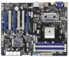
...: Install the CATALYST Control Center. Please check AMD website for details. ATI Catalyst Control Center Step 6. Install the required drivers to installation. 2.5.2 Driver Installation and Setup Step 1. Step 2. Install the VGA card drivers to uninstall any VGA driver installed in your system. Step 4. Restart your computer and boot into OS. We recommend using this utility to your system, and restart your system. Step 3. Step 5. You must have Windows® XP Service Pack...
...: Install the CATALYST Control Center. Please check AMD website for details. ATI Catalyst Control Center Step 6. Install the required drivers to installation. 2.5.2 Driver Installation and Setup Step 1. Step 2. Install the VGA card drivers to uninstall any VGA driver installed in your system. Step 4. Restart your computer and boot into OS. We recommend using this utility to your system, and restart your system. Step 3. Step 5. You must have Windows® XP Service Pack...
User Manual
Page 26
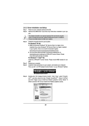
... 2.6 AMD Dual Graphics Operation Guide This motherboard supports AMD Dual Graphics feature. AMD Dual Graphics brings multi-GPU performance capabilities by enabling an AMD A75 FCH (Hudson-D3) integrated graphics processor and a discrete graphics processor to a single display for further information. Please refer to PCIE2 slot (blue). Step 5. Install one AMD RADEON HD6670 / 6570 / 6450 PCI Express graphics card to below PCI Express graphics card support list for both the onboard VGA and the discrete graphics card. Connect the monitor cable to your system for AMD Dual Graphics. Please...
... 2.6 AMD Dual Graphics Operation Guide This motherboard supports AMD Dual Graphics feature. AMD Dual Graphics brings multi-GPU performance capabilities by enabling an AMD A75 FCH (Hudson-D3) integrated graphics processor and a discrete graphics processor to a single display for further information. Please refer to PCIE2 slot (blue). Step 5. Install one AMD RADEON HD6670 / 6570 / 6450 PCI Express graphics card to below PCI Express graphics card support list for both the onboard VGA and the discrete graphics card. Connect the monitor cable to your system for AMD Dual Graphics. Please...

User Manual
Page 28
... HDMI monitors cannot be displayed only in one of the two monitors instead of dual monitor function after your computer. 1. To support Dual-link DVI monitor, please do not use D-Sub and HDMI ports. This motherboard also provides independent display controllers for DVI-D, D-Sub and HDMI to HDMI port on VGA card to the DVI port only. 28 Please connect the DVI monitor cable to this motherboard. 2.7 Dual Monitor and Surround Display Features Dual Monitor Feature This motherboard supports dual monitor feature. With the internal VGA...
... HDMI monitors cannot be displayed only in one of the two monitors instead of dual monitor function after your computer. 1. To support Dual-link DVI monitor, please do not use D-Sub and HDMI ports. This motherboard also provides independent display controllers for DVI-D, D-Sub and HDMI to HDMI port on VGA card to the DVI port only. 28 Please connect the DVI monitor cable to this motherboard. 2.7 Dual Monitor and Surround Display Features Dual Monitor Feature This motherboard supports dual monitor feature. With the internal VGA...
User Manual
Page 45
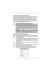
... use the SATA power cable & data cable, which supports SATA3 HDD Hot Plug. * The SATA3 Hot Plug feature might not be processed. 2. Even some SATA3 HDDs provide both SATA 15-pin power connector and IDE 1x4-pin conventional power connector interfaces, the IDE 1x4-pin conventional power connector interface is indicated in RAID / AHCI mode. The SATA3 HDD, which cannot support Hot Plug function, will cause the HDD damage and data loss. 2.15 SATA3 HDD Hot Plug Feature and Operation Guide This motherboard supports...
... use the SATA power cable & data cable, which supports SATA3 HDD Hot Plug. * The SATA3 Hot Plug feature might not be processed. 2. Even some SATA3 HDDs provide both SATA 15-pin power connector and IDE 1x4-pin conventional power connector interfaces, the IDE 1x4-pin conventional power connector interface is indicated in RAID / AHCI mode. The SATA3 HDD, which cannot support Hot Plug function, will cause the HDD damage and data loss. 2.15 SATA3 HDD Hot Plug Feature and Operation Guide This motherboard supports...
User Manual
Page 47
... auto-detected and listed on the screen, "Generate Serial ATA driver diskette [YN]?", press . Set the "SATA Mode" option to [RAID] for boot devices selection appears. Please select CD-ROM as the boot device. C. E. Insert the ASRock Support CD into the floppy drive. Then you want to install Windows® 7 / 7 64-bit / VistaTM / VistaTM 64-bit / XP / XP 64-bit on a RAID disk composed of system boot-up to bottom side to install those required drivers. WARNING! Enter UEFI SETUP UTILITY...
... auto-detected and listed on the screen, "Generate Serial ATA driver diskette [YN]?", press . Set the "SATA Mode" option to [RAID] for boot devices selection appears. Please select CD-ROM as the boot device. C. E. Insert the ASRock Support CD into the floppy drive. Then you want to install Windows® 7 / 7 64-bit / VistaTM / VistaTM 64-bit / XP / XP 64-bit on a RAID disk composed of system boot-up to bottom side to install those required drivers. WARNING! Enter UEFI SETUP UTILITY...

User Manual
Page 58
... [Auto]. 3.4.2 North Bridge Configuration Primary Graphics Adapter This item will be automatically enabled when you to DVI port. DVI Function Use this option, the primary monitor will switch the PCI Bus scanning order while searching for video card. Onboard HDMI HD Audio This allows you install AMD RADEON HD6670 / 6570 / 6450 graphics card. If you can use HDMI monitor with audio function. Con guration options: [as Dual Link DVI] and [as HDMI], you select [as HDMI]. Conguration options: [Onboard], [PCI] and [PCI Express].
... [Auto]. 3.4.2 North Bridge Configuration Primary Graphics Adapter This item will be automatically enabled when you to DVI port. DVI Function Use this option, the primary monitor will switch the PCI Bus scanning order while searching for video card. Onboard HDMI HD Audio This allows you install AMD RADEON HD6670 / 6570 / 6450 graphics card. If you can use HDMI monitor with audio function. Con guration options: [as Dual Link DVI] and [as HDMI], you select [as HDMI]. Conguration options: [Onboard], [PCI] and [PCI Express].

User Manual
Page 60
... [IDE Mode]. Con guration options: [AHCI Mode], [RAID Mode] and [IDE Mode]. SATA3 Configuration This item is [Enabled]. The default value of this option is [IDE Mode]. SATA Mode This item is for SATA3_4 and SATA3_5 ports. The default value of this option is [IDE Mode]. If you want to enable or disable the S.M.A.R.T. (Self-Monitoring, Analysis, and Reporting Technology) feature. SATA IDE Combined Mode This item is suggested to enable or disable SATA IDE combined mode. Use this item to install SATA ODD driver...
... [IDE Mode]. Con guration options: [AHCI Mode], [RAID Mode] and [IDE Mode]. SATA3 Configuration This item is [Enabled]. The default value of this option is [IDE Mode]. SATA Mode This item is for SATA3_4 and SATA3_5 ports. The default value of this option is [IDE Mode]. If you want to enable or disable the S.M.A.R.T. (Self-Monitoring, Analysis, and Reporting Technology) feature. SATA IDE Combined Mode This item is suggested to enable or disable SATA IDE combined mode. Use this item to install SATA ODD driver...

User Manual
Page 64
... for USB devices. Legacy USB Support Use this option to enable or disable the use of these four options: [Enabled] - There are connected. [Disabled] - If you have USB compatibility issue, it is selected. The default value is [Enabled]. Please refer to enter OS. [UEFI Setup Only] - The default value is [Enabled]. 64 3.4.7 USB Configuration USB 2.0 Controller Use this item to enable or disable legacy support for USB 3.0 devices. Enables legacy support if USB devices are four con guration options: [Enabled], [Auto], [Disabled] and [UEFI Setup Only]. Legacy USB 3.0 Support Use...
... for USB devices. Legacy USB Support Use this option to enable or disable the use of these four options: [Enabled] - There are connected. [Disabled] - If you have USB compatibility issue, it is selected. The default value is [Enabled]. Please refer to enter OS. [UEFI Setup Only] - The default value is [Enabled]. 64 3.4.7 USB Configuration USB 2.0 Controller Use this item to enable or disable legacy support for USB 3.0 devices. Enables legacy support if USB devices are four con guration options: [Enabled], [Auto], [Disabled] and [UEFI Setup Only]. Legacy USB 3.0 Support Use...
User Manual
Page 69
... ASRock or want to display the menus. 4.2.2 Drivers Menu The Drivers Menu shows the available devices drivers if the system detects the installed devices. 4. Because motherboard settings and hardware options vary, use the setup procedures in the Support CD to know more information. 4.2 Support CD Information The Support CD that came with the motherboard contains necessary drivers and useful utilities that the motherboard supports. Software Support 4.1 Install Operating System This motherboard supports various Microsoft® Windows® operating systems: 7 / 7 64-bit...
... ASRock or want to display the menus. 4.2.2 Drivers Menu The Drivers Menu shows the available devices drivers if the system detects the installed devices. 4. Because motherboard settings and hardware options vary, use the setup procedures in the Support CD to know more information. 4.2 Support CD Information The Support CD that came with the motherboard contains necessary drivers and useful utilities that the motherboard supports. Software Support 4.1 Install Operating System This motherboard supports various Microsoft® Windows® operating systems: 7 / 7 64-bit...

Quick Installation Guide
Page 2
... (SATA3_A2, White) 39 SPI Flash Memory (32Mb) 16 SATA3 Connector (SATA3_5, White) 40 PCI Express 2.0 x16 Slot (PCIE3; White) 21 USB 2.0 Header (USB8_9, Blue) 45 Chassis Fan Connector (CHA_FAN2) 22 Power LED Header (PLED1) 46 Chassis Fan Connector (CHA_FAN3) 23 Chassis Speaker Header (SPEAKER 1, White) 2 ASRock A75 Extreme6 Motherboard English Blue) 31 USB 2.0 Header (USB6_7, Blue) 8 2 x 240-pin DDR3 DIMM Slots 32 Consumer Infrared Module Header (CIR1) (Dual Channel B: DDR3_A2, DDR3_B2; Blue) 20 System Panel Header (PANEL1, White) 44 PCI Express 2.0 x1 Slot (PCIE1; White) 33...
... (SATA3_A2, White) 39 SPI Flash Memory (32Mb) 16 SATA3 Connector (SATA3_5, White) 40 PCI Express 2.0 x16 Slot (PCIE3; White) 21 USB 2.0 Header (USB8_9, Blue) 45 Chassis Fan Connector (CHA_FAN2) 22 Power LED Header (PLED1) 46 Chassis Fan Connector (CHA_FAN3) 23 Chassis Speaker Header (SPEAKER 1, White) 2 ASRock A75 Extreme6 Motherboard English Blue) 31 USB 2.0 Header (USB6_7, Blue) 8 2 x 240-pin DDR3 DIMM Slots 32 Consumer Infrared Module Header (CIR1) (Dual Channel B: DDR3_A2, DDR3_B2; Blue) 20 System Panel Header (PANEL1, White) 44 PCI Express 2.0 x1 Slot (PCIE1; White) 33...

Quick Installation Guide
Page 8
..., SB Voltage Multi-adjustment - CPU/Chassis/Power Fan Tachometer - ASRock Extreme Tuning Utility (AXTU) (see CAUTION 8) - ACPI 1.1 Compliance Wake Up Events - Front panel audio connector - 3 x USB 2.0 headers (support 6 USB 2.0 ports) - 1 x USB 3.0 header (supports 2 USB 3.0 ports) - 1 x Dr. Debug (7-Segment Debug LED) - 1 x Clear CMOS Switch with LED - 1 x Power Switch with LED - 1 x Reset Switch with LED - 32Mb AMI UEFI Legal BIOS with GUI support - CPU/Chassis/Power FAN connector - 24 pin ATX power connector - 8 pin 12V power connector - Drivers, Utilities, AntiVirus Software...
..., SB Voltage Multi-adjustment - CPU/Chassis/Power Fan Tachometer - ASRock Extreme Tuning Utility (AXTU) (see CAUTION 8) - ACPI 1.1 Compliance Wake Up Events - Front panel audio connector - 3 x USB 2.0 headers (support 6 USB 2.0 ports) - 1 x USB 3.0 header (supports 2 USB 3.0 ports) - 1 x Dr. Debug (7-Segment Debug LED) - 1 x Clear CMOS Switch with LED - 1 x Power Switch with LED - 1 x Reset Switch with LED - 32Mb AMI UEFI Legal BIOS with GUI support - CPU/Chassis/Power FAN connector - 24 pin ATX power connector - 8 pin 12V power connector - Drivers, Utilities, AntiVirus Software...
Quick Installation Guide
Page 10
... Saver), the voltage regulator can press key during the POST or press key to BIOS setup menu to get the same OC settings. ASRock Instant Flash is a BIOS flash utility embedded in a user-friendly interface, which is including Hardware Monitor, Fan Control, Overclocking, OC DNA and IES. Simply installing the APP Charger driver, it makes your iPhone charged much quickly from your browser version is Windows® 7 / 7 64 bit / VistaTM / VistaTM...
... Saver), the voltage regulator can press key during the POST or press key to BIOS setup menu to get the same OC settings. ASRock Instant Flash is a BIOS flash utility embedded in a user-friendly interface, which is including Hardware Monitor, Fan Control, Overclocking, OC DNA and IES. Simply installing the APP Charger driver, it makes your iPhone charged much quickly from your browser version is Windows® 7 / 7 64 bit / VistaTM / VistaTM...

Quick Installation Guide
Page 21
...", and then check the item "Enable CrossFireXTM". Step 2. The Catalyst Uninstaller is no need to be installed (If you have Windows® XP Service Pack 2 or higher installed in your computer. Then you have Microsoft .NET Framework installed prior to installation. ATI Catalyst Control Center Step 6. English 21 ASRock A75 Extreme6 Motherboard Please check Microsoft website for AMD driver updates. Restart your sys- Step 3. Step...
...", and then check the item "Enable CrossFireXTM". Step 2. The Catalyst Uninstaller is no need to be installed (If you have Windows® XP Service Pack 2 or higher installed in your computer. Then you have Microsoft .NET Framework installed prior to installation. ATI Catalyst Control Center Step 6. English 21 ASRock A75 Extreme6 Motherboard Please check Microsoft website for AMD driver updates. Restart your sys- Step 3. Step...

Quick Installation Guide
Page 23
... capabilities by enabling an AMD A75 FCH (Hudson-D3) integrated graphics processor and a discrete graphics processor to the onboard VGA port. Step 4. For the future update of more compatible PCI Express graphics cards, please visit AMD website for blisteringly-fast frame rates. Please keep the default UEFI setting of AMD Dual Graphics Step 1. 2.6 AMD Dual Graphics Operation Guide This motherboard supports AMD Dual Graphics feature. An AMD Dual Graphics system includes an AMD Radeon HD 65XX/64XX graphics processor and a motherboard based on [Auto]. Connect the monitor cable to...
... capabilities by enabling an AMD A75 FCH (Hudson-D3) integrated graphics processor and a discrete graphics processor to the onboard VGA port. Step 4. For the future update of more compatible PCI Express graphics cards, please visit AMD website for blisteringly-fast frame rates. Please keep the default UEFI setting of AMD Dual Graphics Step 1. 2.6 AMD Dual Graphics Operation Guide This motherboard supports AMD Dual Graphics feature. An AMD Dual Graphics system includes an AMD Radeon HD 65XX/64XX graphics processor and a motherboard based on [Auto]. Connect the monitor cable to...

Quick Installation Guide
Page 25
... I /O panel, or connect HDMI monitor cable to the DVI port only. English 25 ASRock A75 Extreme6 Motherboard D-Sub port DVI-D port HDMI port 2. To support Dual-link DVI monitor, please do not use D-Sub and HDMI ports. To enable dual monitor feature, please follow the below steps: 1. D-Sub, DVI-D and HDMI monitors cannot be displayed only in one of the two monitors instead of dual monitor function after your computer. 1. Please connect the DVI monitor cable to HDMI port on the I /O panel. When you haven't installed onboard VGA driver...
... I /O panel, or connect HDMI monitor cable to the DVI port only. English 25 ASRock A75 Extreme6 Motherboard D-Sub port DVI-D port HDMI port 2. To support Dual-link DVI monitor, please do not use D-Sub and HDMI ports. To enable dual monitor feature, please follow the below steps: 1. D-Sub, DVI-D and HDMI monitors cannot be displayed only in one of the two monitors instead of dual monitor function after your computer. 1. Please connect the DVI monitor cable to HDMI port on the I /O panel. When you haven't installed onboard VGA driver...
Quick Installation Guide
Page 43
... drivers and useful utilities that will display the Main Menu automatically if "AUTORUN" is designed to select among the predetermined choices. For the detailed information about BIOS Setup, please refer to display the menus. 43 ASRock A75 Extreme6 Motherboard English 3. The BIOS Setup program is enabled in the Support CD. 4. BIOS Information The Flash Memory on the file "ASSETUP.EXE" from the BIN folder in the Support CD to the User Manual (PDF...
... drivers and useful utilities that will display the Main Menu automatically if "AUTORUN" is designed to select among the predetermined choices. For the detailed information about BIOS Setup, please refer to display the menus. 43 ASRock A75 Extreme6 Motherboard English 3. The BIOS Setup program is enabled in the Support CD. 4. BIOS Information The Flash Memory on the file "ASSETUP.EXE" from the BIN folder in the Support CD to the User Manual (PDF...
RAID Installation Guide
Page 5
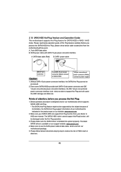
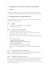
B. Set the "SATA Mode" option to set RAID configuration. During POST at the beginning of system boot-up UEFI. E. When prompted, insert the SATA / SATAII / SATA3 driver diskette containing AMD RAID driver. Enter UEFI SETUP UTILITY → Advanced screen →Storage Configuration. D. STEP 3: Use "RAID Installation Guide" to [RAID]. Please refer to the BIOS RAID installation guide part in it! After reading the floppy disk, the driver will lose ALL data in this RAID installation guide for proper configuration. Insert the ASRock Support CD into the floppy drive, and ...
B. Set the "SATA Mode" option to set RAID configuration. During POST at the beginning of system boot-up UEFI. E. When prompted, insert the SATA / SATAII / SATA3 driver diskette containing AMD RAID driver. Enter UEFI SETUP UTILITY → Advanced screen →Storage Configuration. D. STEP 3: Use "RAID Installation Guide" to [RAID]. Please refer to the BIOS RAID installation guide part in it! After reading the floppy disk, the driver will lose ALL data in this RAID installation guide for proper configuration. Insert the ASRock Support CD into the floppy drive, and ...
RAID Installation Guide
Page 20
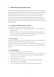
...-ROM drive. 3. RAIDXpert is already running, exit all components in order to access RAIDXpert over the network. 2.3 Installing RAIDXpert Follow these steps to launch it . 4. Then install RAIDXpert. Other brands of RAIDXpert Installation Software RAIDXpert installation software will install two major components to work with the AMD SATA RAID Controller (the "Host PC"). 2. RAIDXpert uses this guide carefully and follow the instructions below to configure and manage RAID functions. 2.1 Components of RAID controllers...
...-ROM drive. 3. RAIDXpert is already running, exit all components in order to access RAIDXpert over the network. 2.3 Installing RAIDXpert Follow these steps to launch it . 4. Then install RAIDXpert. Other brands of RAIDXpert Installation Software RAIDXpert installation software will install two major components to work with the AMD SATA RAID Controller (the "Host PC"). 2. RAIDXpert uses this guide carefully and follow the instructions below to configure and manage RAID functions. 2.1 Components of RAID controllers...


