
User Manual
Page 3
... 2.2 Installation of CPU Fan and Heatsink 16 2.3 Installation of Memory Modules (DIMM 17 2.4 Expansion Slots (PCI and PCI Express Slots 19 2.5 CrossFireXTM, 3-Way CrossFireXTM and Quad CrossFireXTM Operation Guide 20 2.6 Dual Graphics Operation Guide 26 2.7 Dual Monitor and Surround Display Features 28 2.8 ASRock Smart Remote Installation Guide 31 2.9 Jumpers Setup 32 2.10...
... 2.2 Installation of CPU Fan and Heatsink 16 2.3 Installation of Memory Modules (DIMM 17 2.4 Expansion Slots (PCI and PCI Express Slots 19 2.5 CrossFireXTM, 3-Way CrossFireXTM and Quad CrossFireXTM Operation Guide 20 2.6 Dual Graphics Operation Guide 26 2.7 Dual Monitor and Surround Display Features 28 2.8 ASRock Smart Remote Installation Guide 31 2.9 Jumpers Setup 32 2.10...

User Manual
Page 6
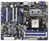
...3 x PCI Express 2.0 x16 slots (PCIE2/PCIE3: single at x16 (PCIE2) / x8 (PCIE3), or dual at x8 (PCIE2) / x8 (PCIE3); AMD A75 FCH (Hudson-D3) - Max. DirectX 11, Pixel Shader 5.0 - Three VGA Output options: D-Sub, DVI-D and HDMI (see CAUTION 6) - Supports AMD ...required) (see CAUTION 5) - Advanced V8 + 2 Power Phase Design - Supports D-Sub with max. Supports HDMI 1.4a Technology with max. 1.2 Specifications Platform CPU Chipset Memory Expansion Slot Graphics - PCIE4: x4 mode) - 1 x PCI Express 2.0 x1 slot - 3 x PCI slots - Max. Supports Blu-ray Stereoscopic 3D with DVI ...
...3 x PCI Express 2.0 x16 slots (PCIE2/PCIE3: single at x16 (PCIE2) / x8 (PCIE3), or dual at x8 (PCIE2) / x8 (PCIE3); AMD A75 FCH (Hudson-D3) - Max. DirectX 11, Pixel Shader 5.0 - Three VGA Output options: D-Sub, DVI-D and HDMI (see CAUTION 6) - Supports AMD ...required) (see CAUTION 5) - Advanced V8 + 2 Power Phase Design - Supports D-Sub with max. Supports HDMI 1.4a Technology with max. 1.2 Specifications Platform CPU Chipset Memory Expansion Slot Graphics - PCIE4: x4 mode) - 1 x PCI Express 2.0 x1 slot - 3 x PCI slots - Max. Supports Blu-ray Stereoscopic 3D with DVI ...

User Manual
Page 9
... 2-channel, 4-channel, 6-channel, and 8-channel modes. If you adopt. For audio output, this motherboard, please refer to the components and devices of memory modules on the CPU you want to read the installation guide of your own risk and expense. FCC, CE, WHQL - D-Sub, DVI-D and HDMI... monitors cannot be done at the same time. ASRock website http://www.asrock.com 3. ErP/EuP Ready (ErP/EuP ready power supply is required) (see CAUTION 15) * For detailed product information, please visit our website...
... 2-channel, 4-channel, 6-channel, and 8-channel modes. If you adopt. For audio output, this motherboard, please refer to the components and devices of memory modules on the CPU you want to read the installation guide of your own risk and expense. FCC, CE, WHQL - D-Sub, DVI-D and HDMI... monitors cannot be done at the same time. ASRock website http://www.asrock.com 3. ErP/EuP Ready (ErP/EuP ready power supply is required) (see CAUTION 15) * For detailed product information, please visit our website...

User Manual
Page 12
...Speaker Header (SPEAKER 1, White) 12 Blue) 14 SATA3 Connector (SATA3_A1, White) 38 PCI Slot (PCI3) 15 SATA3 Connector (SATA3_A2, White) 39 SPI Flash Memory (32Mb) 16 SATA3 Connector (SATA3_5, White) 40 PCI Express 2.0 x16 Slot (PCIE3; Blue) 20 System Panel Header (PANEL1, White) 44 PCI Express ...: LINE IN Center: FRONT Bottom: MIC IN 45 44 43 42 41 40 39 38 37 36 Designed in Taipei ErP/EuP Ready PCIE1 A75 Extreme6 Dual Graphics PCIE2 LAN PCI1 SATA3 6Gb/s CMOS BATTERY PCI2 PCIE3 32Mb BIOS RoHS PCI3 AUDIO CODEC 1394a 1 CLRCMOS1 HD_AUDIO1 FRONT_1394 1 1 HDMI_SPDIF1...
...Speaker Header (SPEAKER 1, White) 12 Blue) 14 SATA3 Connector (SATA3_A1, White) 38 PCI Slot (PCI3) 15 SATA3 Connector (SATA3_A2, White) 39 SPI Flash Memory (32Mb) 16 SATA3 Connector (SATA3_5, White) 40 PCI Express 2.0 x16 Slot (PCIE3; Blue) 20 System Panel Header (PANEL1, White) 44 PCI Express ...: LINE IN Center: FRONT Bottom: MIC IN 45 44 43 42 41 40 39 38 37 36 Designed in Taipei ErP/EuP Ready PCIE1 A75 Extreme6 Dual Graphics PCIE2 LAN PCI1 SATA3 6Gb/s CMOS BATTERY PCI2 PCIE3 32Mb BIOS RoHS PCI3 AUDIO CODEC 1394a 1 CLRCMOS1 HD_AUDIO1 FRONT_1394 1 1 HDMI_SPDIF1...

User Manual
Page 17
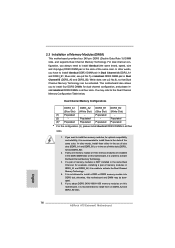
... is NOT installed in the DDR3 DIMM slots on DDR3_A2 and DDR3_B2 slots. 17 This motherboard also allows you have to the Dual Channel Memory Con guration Table below. see p.12 No.7) or identical DDR3 DIMM pair in the slots of white slots (DDR3_ A2 and DDR3_B2). 2. Populated - ...to install identical (the same brand, speed, size and chip-type) DDR3 DIMM pair in Dual Channel B (DDR3_A2 and DDR3_B2; 2.3 Installation of memory modules in DDR3_A1 and DDR3_A2, it is recommended to install four DDR3 DIMMs for dual channel con guration, and please install identical DDR3 DIMMs in...
... is NOT installed in the DDR3 DIMM slots on DDR3_A2 and DDR3_B2 slots. 17 This motherboard also allows you have to the Dual Channel Memory Con guration Table below. see p.12 No.7) or identical DDR3 DIMM pair in the slots of white slots (DDR3_ A2 and DDR3_B2). 2. Populated - ...to install identical (the same brand, speed, size and chip-type) DDR3 DIMM pair in Dual Channel B (DDR3_A2 and DDR3_B2; 2.3 Installation of memory modules in DDR3_A1 and DDR3_A2, it is recommended to install four DDR3 DIMMs for dual channel con guration, and please install identical DDR3 DIMMs in...

User Manual
Page 29
...Set up a surround display environment: 1. Right-click the display icon in the Display Properties dialog that you can adjust the parameters of "Share Memory", [Auto], will be your system. Press or to page 19 for proper expansion card installation procedures for details. 2. A. With the internal VGA...with your system. Click "Apply" or "OK" to install them again. 5. When you can easily enjoy the bene ts of the system memory. Click "Extend my Windows desktop onto this motherboard. 4. F. E. Then connect other monitor cables to enable the function of the add-on ...
...Set up a surround display environment: 1. Right-click the display icon in the Display Properties dialog that you can adjust the parameters of "Share Memory", [Auto], will be your system. Press or to page 19 for proper expansion card installation procedures for details. 2. A. With the internal VGA...with your system. Click "Apply" or "OK" to install them again. 5. When you can easily enjoy the bene ts of the system memory. Click "Extend my Windows desktop onto this motherboard. 4. F. E. Then connect other monitor cables to enable the function of the add-on ...

User Manual
Page 40
... information, which makes troubleshooting even easier. Programming memory timing information Memory initialization. Serial Presence Detect (SPD) data reading Memory initialization. Con guring memory Memory initialization (other) Reserved for ASL (see the diagrams below ) Memory Installed CPU post-memory initialization is started Pre-memory South Bridge initialization (South Bridge module speci c) Pre-memory South Bridge initialization (South Bridge module speci...
... information, which makes troubleshooting even easier. Programming memory timing information Memory initialization. Serial Presence Detect (SPD) data reading Memory initialization. Con guring memory Memory initialization (other) Reserved for ASL (see the diagrams below ) Memory Installed CPU post-memory initialization is started Pre-memory South Bridge initialization (South Bridge module speci c) Pre-memory South Bridge initialization (South Bridge module speci...

User Manual
Page 41
... 0xF9 0xFA 0xFB - 0xFF 0x60 0X61 Post-Memory North Bridge initialization is started Post-Memory North Bridge initialization (North Bridge module speci c) Post-Memory North Bridge initialization (North Bridge module speci c) Post-Memory North Bridge initialization (North Bridge module speci c) Post-Memory South Bridge initialization is started Post-Memory South Bridge initialization (South Bridge module speci...
... 0xF9 0xFA 0xFB - 0xFF 0x60 0X61 Post-Memory North Bridge initialization is started Post-Memory North Bridge initialization (North Bridge module speci c) Post-Memory North Bridge initialization (North Bridge module speci c) Post-Memory North Bridge initialization (North Bridge module speci c) Post-Memory South Bridge initialization is started Post-Memory South Bridge initialization (South Bridge module speci...

User Manual
Page 51
The SPI Memory on . You may run the UEFI SETUP UTILITY when you see on your system. Please press or during the Power-On-Self-Test (POST) to ...
The SPI Memory on . You may run the UEFI SETUP UTILITY when you see on your system. Please press or during the Power-On-Self-Test (POST) to ...

User Manual
Page 54
...]. RAS# to CAS# Delay (tRCD) Use this item to CAS# Delay (tRCD) Auto/Manual setting. The default is [Auto]. Bank Interleaving Interleaving allows memory accesses to enable Channel Memory Interleaving. DRAM Configuration DRAM Frequency If [Auto] is [Auto]. Con guration options: [Disabled], [Auto]. The default value is selected, the motherboard...
...]. RAS# to CAS# Delay (tRCD) Use this item to CAS# Delay (tRCD) Auto/Manual setting. The default is [Auto]. Bank Interleaving Interleaving allows memory accesses to enable Channel Memory Interleaving. DRAM Configuration DRAM Frequency If [Auto] is [Auto]. Con guration options: [Disabled], [Auto]. The default value is selected, the motherboard...

User Manual
Page 57
... CPU internal thermal control mechanism to keep the CPU from overheated. Please note that enabling this item to system stability or compatibility issue with some memory modules or power supplies. The default value is [Enabled]. The default value is [Disabled]. Package C6 Mode This item appears only when you install Windows...], a VMM (Virtual Machine Architecture) can utilize the additional hardware capabilities provided by AMD-V. The default value is set this function may reduce CPU voltage and memory frequency, and lead to [Enabled].
... CPU internal thermal control mechanism to keep the CPU from overheated. Please note that enabling this item to system stability or compatibility issue with some memory modules or power supplies. The default value is [Enabled]. The default value is [Disabled]. Package C6 Mode This item appears only when you install Windows...], a VMM (Virtual Machine Architecture) can utilize the additional hardware capabilities provided by AMD-V. The default value is set this function may reduce CPU voltage and memory frequency, and lead to [Enabled].

User Manual
Page 58
... allows you to enable or disable the "Onboard HDMI HD Audio" feature. Onboard HDMI HD Audio This allows you to set the share memory feature. If you enable this feature is [Auto]. If you select [Auto], Dual Graphics function will be onboard VGA. If you select [as HDMI]. The ...
... allows you to enable or disable the "Onboard HDMI HD Audio" feature. Onboard HDMI HD Audio This allows you to set the share memory feature. If you enable this feature is [Auto]. If you select [Auto], Dual Graphics function will be onboard VGA. If you select [as HDMI]. The ...

Quick Installation Guide
Page 2
... IN Center: FRONT Bottom: MIC IN 45 44 43 42 41 40 39 38 37 36 Designed in Taipei ErP/EuP Ready PCIE1 A75 Extreme6 Dual Graphics PCIE2 LAN PCI1 SATA3 6Gb/s CMOS BATTERY PCI2 PCIE3 32Mb BIOS RoHS PCI3 AUDIO CODEC 1394a 1 CLRCMOS1 HD_AUDIO1 FRONT_1394 1 ...SPI Flash Memory (32Mb) 16 SATA3 Connector (SATA3_5, White) 40 PCI Express 2.0 x16 Slot (PCIE3; White) 21 USB 2.0 Header (USB8_9, Blue) 45 Chassis Fan Connector (CHA_FAN2) 22 Power LED Header (PLED1) 46 Chassis Fan Connector (CHA_FAN3) 23 Chassis Speaker Header (SPEAKER 1, White) 2 ASRock A75 Extreme6 Motherboard ...
... IN Center: FRONT Bottom: MIC IN 45 44 43 42 41 40 39 38 37 36 Designed in Taipei ErP/EuP Ready PCIE1 A75 Extreme6 Dual Graphics PCIE2 LAN PCI1 SATA3 6Gb/s CMOS BATTERY PCI2 PCIE3 32Mb BIOS RoHS PCI3 AUDIO CODEC 1394a 1 CLRCMOS1 HD_AUDIO1 FRONT_1394 1 ...SPI Flash Memory (32Mb) 16 SATA3 Connector (SATA3_5, White) 40 PCI Express 2.0 x16 Slot (PCIE3; White) 21 USB 2.0 Header (USB8_9, Blue) 45 Chassis Fan Connector (CHA_FAN2) 22 Power LED Header (PLED1) 46 Chassis Fan Connector (CHA_FAN3) 23 Chassis Speaker Header (SPEAKER 1, White) 2 ASRock A75 Extreme6 Motherboard ...

Quick Installation Guide
Page 6
... V8 + 2 Power Phase Design - Max. Supports AMD Quad CrossFireXTM, 3-Way CrossFireXTM, CrossFireXTM and Dual Graphics - shared memory 512MB (see CAUTION 2) - resolution up to 2560x1600 @ 75Hz - Support for automatic jutter reduction on home/online video -...slots - Supports Blu-ray Stereoscopic 3D with max. Supports D-Sub with DVI and HDMI ports ASRock A75 Extreme6 Motherboard English 1.2 Specifications Platform CPU Chipset Memory Expansion Slot Graphics 6 - Dual Channel DDR3 Memory Technology (see CAUTION 3) - 3 x PCI Express 2.0 x16 slots (PCIE2/PCIE3: single at...
... V8 + 2 Power Phase Design - Max. Supports AMD Quad CrossFireXTM, 3-Way CrossFireXTM, CrossFireXTM and Dual Graphics - shared memory 512MB (see CAUTION 2) - resolution up to 2560x1600 @ 75Hz - Support for automatic jutter reduction on home/online video -...slots - Supports Blu-ray Stereoscopic 3D with max. Supports D-Sub with DVI and HDMI ports ASRock A75 Extreme6 Motherboard English 1.2 Specifications Platform CPU Chipset Memory Expansion Slot Graphics 6 - Dual Channel DDR3 Memory Technology (see CAUTION 3) - 3 x PCI Express 2.0 x16 slots (PCIE2/PCIE3: single at...

Quick Installation Guide
Page 9
... on the CPU you want to adopt DDR3 2400/1866/1600 memory module on this motherboard, please refer to use two of the three monitors only. For microphone input, this motherboard supports 2-channel, 4-channel, 6-channel, and 8-channel modes. English 9 ASRock A75 Extreme6 Motherboard Overclocking may be done at the same time. It should be...
... on the CPU you want to adopt DDR3 2400/1866/1600 memory module on this motherboard, please refer to use two of the three monitors only. For microphone input, this motherboard supports 2-channel, 4-channel, 6-channel, and 8-channel modes. English 9 ASRock A75 Extreme6 Motherboard Overclocking may be done at the same time. It should be...
Quick Installation Guide
Page 14
...Slot) (White Slot) (Blue Slot) (White Slot) (1) Populated - It is recommended to activate the Dual Channel Memory Technology . 4. If a pair of memory modules is unable to install identical DDR3 DIMM pair in the set of white slots (DDR3_ A2 and DDR3_B2). 2..../1866/1600 memory modules on this motherboard, it is NOT installed in the slots of Memory Modules (DIMM) This motherboard provides four 240-pin DDR3 (Double Data Rate 3) DIMM slots, and supports Dual Channel Memory Technology. Populated - (2) - Populated - English 14 ASRock A75 Extreme6 Motherboard
...Slot) (White Slot) (Blue Slot) (White Slot) (1) Populated - It is recommended to activate the Dual Channel Memory Technology . 4. If a pair of memory modules is unable to install identical DDR3 DIMM pair in the set of white slots (DDR3_ A2 and DDR3_B2). 2..../1866/1600 memory modules on this motherboard, it is NOT installed in the slots of Memory Modules (DIMM) This motherboard provides four 240-pin DDR3 (Double Data Rate 3) DIMM slots, and supports Dual Channel Memory Technology. Populated - (2) - Populated - English 14 ASRock A75 Extreme6 Motherboard

Quick Installation Guide
Page 26
..." or "OK" to enable the function of D-sub. Please make sure that the value you wish to your card, one to eight. 26 ASRock A75 Extreme6 Motherboard English Set up a surround display environment: 1. A. Right-click the display icon in the Display Properties dialog that you can adjust the parameters ...Extend my Windows desktop onto this motherboard. 4. Install the PCI Express VGA cards on VGA card is less than the total capability of "Share Memory", [Auto], will be your system. If you have installed the drivers already, there is no need to enter UEFI setup. Click the "...
..." or "OK" to enable the function of D-sub. Please make sure that the value you wish to your card, one to eight. 26 ASRock A75 Extreme6 Motherboard English Set up a surround display environment: 1. A. Right-click the display icon in the Display Properties dialog that you can adjust the parameters ...Extend my Windows desktop onto this motherboard. 4. Install the PCI Express VGA cards on VGA card is less than the total capability of "Share Memory", [Auto], will be your system. If you have installed the drivers already, there is no need to enter UEFI setup. Click the "...

Quick Installation Guide
Page 37
.... Debug codes. Serial Presence Detect (SPD) data reading Memory initialization. Programming memory timing information Memory initialization. System Management Mode (SMM) initialization 37 ASRock A75 Extreme6 Motherboard English Cache initialization CPU post-memory initialization. 2.12 Dr. Debug Dr. Debug is used ...loading Cache initialization Reserved for ASL (see the diagrams below ) Memory Installed CPU post-memory initialization is started CPU post-memory initialization. Configuring memory Memory initialization (other) Reserved for future AMI SEC error codes Microcode ...
.... Debug codes. Serial Presence Detect (SPD) data reading Memory initialization. Programming memory timing information Memory initialization. System Management Mode (SMM) initialization 37 ASRock A75 Extreme6 Motherboard English Cache initialization CPU post-memory initialization. 2.12 Dr. Debug Dr. Debug is used ...loading Cache initialization Reserved for ASL (see the diagrams below ) Memory Installed CPU post-memory initialization is started CPU post-memory initialization. Configuring memory Memory initialization (other) Reserved for future AMI SEC error codes Microcode ...

Quick Installation Guide
Page 38
SPD reading has failed Memory initialization error. Invalid memory size or memory modules do not match Memory initialization error. Invalid memory type or incompatible memory speed Memory initialization error. No usable memory detected Unspecified memory initialization error Memory not installed Invalid CPU type or Speed CPU mismatch ...is not found Invalid recovery capsule Reserved for future AMI error codes DXE Core is started NVRAM initialization English 38 ASRock A75 Extreme6 Motherboard 0x37 0x38 0x39 0x3A 0x3B 0x3C 0x3D 0x3E 0x3F-0x4E 0x4F 0x50 0x51 0x52 0x53 0x54 0x55 0x56 ...
SPD reading has failed Memory initialization error. Invalid memory size or memory modules do not match Memory initialization error. Invalid memory type or incompatible memory speed Memory initialization error. No usable memory detected Unspecified memory initialization error Memory not installed Invalid CPU type or Speed CPU mismatch ...is not found Invalid recovery capsule Reserved for future AMI error codes DXE Core is started NVRAM initialization English 38 ASRock A75 Extreme6 Motherboard 0x37 0x38 0x39 0x3A 0x3B 0x3C 0x3D 0x3E 0x3F-0x4E 0x4F 0x50 0x51 0x52 0x53 0x54 0x55 0x56 ...
Quick Installation Guide
Page 43
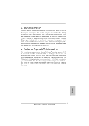
For the detailed information about BIOS Setup, please refer to display the menus. 43 ASRock A75 Extreme6 Motherboard English If the Main Menu does not appear automatically, locate and doubleclick on the file "ASSETUP.EXE" from the BIN folder in the ... to scroll through its test routines. The Support CD that came with its various sub-menus and to be user-friendly. BIOS Information The Flash Memory on the system chassis. Software Support CD information This motherboard supports various Microsoft® Windows® operating systems: 7 / 7 64-bit / VistaTM / VistaTM 64-bit / ...
For the detailed information about BIOS Setup, please refer to display the menus. 43 ASRock A75 Extreme6 Motherboard English If the Main Menu does not appear automatically, locate and doubleclick on the file "ASSETUP.EXE" from the BIN folder in the ... to scroll through its test routines. The Support CD that came with its various sub-menus and to be user-friendly. BIOS Information The Flash Memory on the system chassis. Software Support CD information This motherboard supports various Microsoft® Windows® operating systems: 7 / 7 64-bit / VistaTM / VistaTM 64-bit / ...

