
User Manual
Page 1
All rights reserved. 1 A75 Extreme6 User Manual Version 1.1 Published June 2011 Copyright©2011 ASRock INC.
All rights reserved. 1 A75 Extreme6 User Manual Version 1.1 Published June 2011 Copyright©2011 ASRock INC.

User Manual
Page 2
Operation is subject to change without notice, and should not be constructed as a commitment by ASRock. Disclaimer: Speci cations and information contained in this manual are used only for identi cation or explanation and to the owners' bene t, without written consent of any kind, ...undesired operation. With respect to the contents of this manual. CALIFORNIA, USA ONLY The Lithium battery adopted on this manual may or may not be liable for any defect or error in this manual, ASRock does not provide warranty of ASRock Inc. Products and corporate names appearing in this ...
Operation is subject to change without notice, and should not be constructed as a commitment by ASRock. Disclaimer: Speci cations and information contained in this manual are used only for identi cation or explanation and to the owners' bene t, without written consent of any kind, ...undesired operation. With respect to the contents of this manual. CALIFORNIA, USA ONLY The Lithium battery adopted on this manual may or may not be liable for any defect or error in this manual, ASRock does not provide warranty of ASRock Inc. Products and corporate names appearing in this ...
User Manual
Page 5
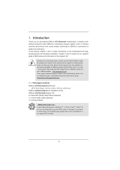
... Contents ASRock A75 Extreme6 Motherboard (ATX Form Factor: 12.0-in x 9.6-in our support CD for purchasing ASRock A75 Extreme6 motherboard, a reliable motherboard produced under ASRock's consistently stringent quality control. For the BIOS setup, please refer to change without further notice. In this manual will be subject to the "User Manual" in , 30.5 cm x 24.4 cm) ASRock A75 Extreme6 Quick Installation Guide ASRock A75 Extreme6 Support...
... Contents ASRock A75 Extreme6 Motherboard (ATX Form Factor: 12.0-in x 9.6-in our support CD for purchasing ASRock A75 Extreme6 motherboard, a reliable motherboard produced under ASRock's consistently stringent quality control. For the BIOS setup, please refer to change without further notice. In this manual will be subject to the "User Manual" in , 30.5 cm x 24.4 cm) ASRock A75 Extreme6 Quick Installation Guide ASRock A75 Extreme6 Support...

User Manual
Page 16
... CPU into the socket until it ts in place, press it is in place. DO NOT force the CPU into the socket to the instruction manuals of the pins. Unlock the socket by lifting the lever up to secure the CPU.
... CPU into the socket until it ts in place, press it is in place. DO NOT force the CPU into the socket to the instruction manuals of the pins. Unlock the socket by lifting the lever up to secure the CPU.

User Manual
Page 20
For other Radeon graphics card to AMD graphics card manuals for AMD CrossFireXTM driver updates. 1. Combining a range of performance and image quality in the future, please refer to PCIE3 slot. Make sure that AMD has ...
For other Radeon graphics card to AMD graphics card manuals for AMD CrossFireXTM driver updates. 1. Combining a range of performance and image quality in the future, please refer to PCIE3 slot. Make sure that AMD has ...

User Manual
Page 35
... your system using the power switch. The LED keeps blinking when the sys-tem is on the chassis front panel. The LED is in our manual and chassis manual to turn off (S5).
... your system using the power switch. The LED keeps blinking when the sys-tem is on the chassis front panel. The LED is in our manual and chassis manual to turn off (S5).
User Manual
Page 45
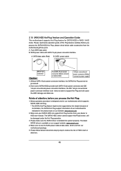
... SATA3 driver is installed into system properly. Please make sure the SATA3 driver is available on our website: www.asrock.com 2. Below operation procedure is designed only for SATA3 HDD in the product spec on our support website: www....asrock.com 4. A. 7-pin SATA data cable B. The SATA3 HDD, which are from our motherboard package. 5. Even some SATA3 ... data loss. Make sure to power supply 1. Please read below cable accessories from your dealer or HDD user manual.
... SATA3 driver is installed into system properly. Please make sure the SATA3 driver is available on our website: www.asrock.com 2. Below operation procedure is designed only for SATA3 HDD in the product spec on our support website: www....asrock.com 4. A. 7-pin SATA data cable B. The SATA3 HDD, which are from our motherboard package. 5. Even some SATA3 ... data loss. Make sure to power supply 1. Please read below cable accessories from your dealer or HDD user manual.

User Manual
Page 53
... will display Processor Maximum Voltage for better system stability. CPU Frequency Multiplier For safety and system stability, it is set the item "Overclock Mode" to [Manual]. Use this feature. If it is [Auto]. The default value is recommended to keep the default value for reference. Con guration options: [Auto] and [.... 53 It is [100]. The default value is set up overclocking features. 3.3 OC Tweaker Screen In the OC Tweaker screen, you can set to [Manual], you may reduce the D-Sub resolution and cause the display abnormal situation. Configuration options: [Auto] and...
... will display Processor Maximum Voltage for better system stability. CPU Frequency Multiplier For safety and system stability, it is set the item "Overclock Mode" to [Manual]. Use this feature. If it is [Auto]. The default value is recommended to keep the default value for reference. Con guration options: [Auto] and [.... 53 It is [100]. The default value is set up overclocking features. 3.3 OC Tweaker Screen In the OC Tweaker screen, you can set to [Manual], you may reduce the D-Sub resolution and cause the display abnormal situation. Configuration options: [Auto] and...

User Manual
Page 54
...(tRAS) Use this item. Channel Interleaving It allows you to adjust the value of this item to change RAS# to CAS# Delay (tRCD) Auto/Manual setting. Con guration options: [Disabled], [Auto]. The default is not recommended to adjust the value of CPU voltage. CPU Voltage It allows you to... memory module(s) inserted and assigns appropriate frequency automatically. DRAM Timing Control Power Down Enable Use this item to change RAS# Active Time (tRAS) Auto/Manual setting. RAS# to CAS# Delay (tRCD) Use this item to be spread out over banks on the same node, or accross nodes, decreasing ...
...(tRAS) Use this item. Channel Interleaving It allows you to adjust the value of this item to change RAS# to CAS# Delay (tRCD) Auto/Manual setting. Con guration options: [Disabled], [Auto]. The default is not recommended to adjust the value of CPU voltage. CPU Voltage It allows you to... memory module(s) inserted and assigns appropriate frequency automatically. DRAM Timing Control Power Down Enable Use this item to change RAS# Active Time (tRAS) Auto/Manual setting. RAS# to CAS# Delay (tRCD) Use this item to be spread out over banks on the same node, or accross nodes, decreasing ...

User Manual
Page 55
...Auto]. The default value is [Auto]. The default is [Auto]. The default is [Auto]. In this item to change Write to Read Delay (tWTR) Auto/Manual setting. The default is [Auto]. Read to Precharge (tRTP) Use this to select APU PCIE Voltage VDDP. Min: 1T. The default is [Auto]. RAS ... this to select DRAM Voltage. The default is [Auto]. Voltage Control DRAM Voltage Use this item to change RAS to RAS Delay (tRRD) Auto/Manual setting. Would you are allowed to load and save current setting user defaults? Command Rate (CR) Use this item to change Write Recovery Time (tWR...
...Auto]. The default value is [Auto]. The default is [Auto]. The default is [Auto]. In this item to change Write to Read Delay (tWTR) Auto/Manual setting. The default is [Auto]. Read to Precharge (tRTP) Use this to select APU PCIE Voltage VDDP. Min: 1T. The default is [Auto]. RAS ... this to select DRAM Voltage. The default is [Auto]. Voltage Control DRAM Voltage Use this item to change RAS to RAS Delay (tRRD) Auto/Manual setting. Would you are allowed to load and save current setting user defaults? Command Rate (CR) Use this item to change Write Recovery Time (tWR...

User Manual
Page 65
Con guration options: [Full On] and [Manual Mode]. The default is value [Full On]. Chassis Fan 2 Setting This allows you to monitor the status of the hardware on your system, including the ...]. Chassis Fan 3 Setting This allows you to set the chassis fan 3 speed. The default is value [Full On]. 65 Con guration options: [Full On] and [Manual Mode]. Con guration options: [Full On], [Manual Mode] and [Automatic Mode]. Con guration options: [Full On] and [Automatic Mode].
Con guration options: [Full On] and [Manual Mode]. The default is value [Full On]. Chassis Fan 2 Setting This allows you to monitor the status of the hardware on your system, including the ...]. Chassis Fan 3 Setting This allows you to set the chassis fan 3 speed. The default is value [Full On]. 65 Con guration options: [Full On] and [Manual Mode]. Con guration options: [Full On], [Manual Mode] and [Automatic Mode]. Con guration options: [Full On] and [Automatic Mode].
Quick Installation Guide
Page 5
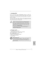
... support CD for purchasing ASRock A75 Extreme6 motherboard, a reliable motherboard produced under ASRock's consistently stringent quality control. 1. ASRock website http://www.asrock.com If you for details. 5 ASRock A75 Extreme6 Motherboard English This Quick Installation Guide contains introduction of this manual will be found in the user manual presented in , 30.5 cm x 24.4 cm) ASRock A75 Extreme6 Quick Installation Guide ASRock A75 Extreme6 Support CD 4 x Serial ATA...
... support CD for purchasing ASRock A75 Extreme6 motherboard, a reliable motherboard produced under ASRock's consistently stringent quality control. 1. ASRock website http://www.asrock.com If you for details. 5 ASRock A75 Extreme6 Motherboard English This Quick Installation Guide contains introduction of this manual will be found in the user manual presented in , 30.5 cm x 24.4 cm) ASRock A75 Extreme6 Quick Installation Guide ASRock A75 Extreme6 Support CD 4 x Serial ATA...

Quick Installation Guide
Page 13
Step 2. Carefully insert the CPU into the socket until it is necessary to install a larger heatsink and cooling fan to the instruction manuals of the pins. Step 3. Step 4. For proper installation, please kindly refer to dissipate heat. Lever 90° Up STEP 1: Lift Up The Socket Lever CPU .... You also need to spray thermal grease between the CPU and the heatsink to avoid bending of the CPU fan and the heatsink. English 13 ASRock A75 Extreme6 Motherboard
Step 2. Carefully insert the CPU into the socket until it is necessary to install a larger heatsink and cooling fan to the instruction manuals of the pins. Step 3. Step 4. For proper installation, please kindly refer to dissipate heat. Lever 90° Up STEP 1: Lift Up The Socket Lever CPU .... You also need to spray thermal grease between the CPU and the heatsink to avoid bending of the CPU fan and the heatsink. English 13 ASRock A75 Extreme6 Motherboard

Quick Installation Guide
Page 17
If a customer incorrectly configures their system they will release in any 3D application. Step 1. English 17 ASRock A75 Extreme6 Motherboard Combining a range of performance and image quality in the future, please refer to PCIE3 slot. If you pair a 12-pipe... enables the highest possible level of different operating modes with Windows® VistaTM / 7 OS only. For other Radeon graphics card to AMD graphics card manuals for AMD CrossFireXTM driver updates. 1. Currently CrossFireXTM feature is supported with Windows® XP with Service Pack 2 / VistaTM / 7 OS. 3-way ...
If a customer incorrectly configures their system they will release in any 3D application. Step 1. English 17 ASRock A75 Extreme6 Motherboard Combining a range of performance and image quality in the future, please refer to PCIE3 slot. If you pair a 12-pipe... enables the highest possible level of different operating modes with Windows® VistaTM / 7 OS only. For other Radeon graphics card to AMD graphics card manuals for AMD CrossFireXTM driver updates. 1. Currently CrossFireXTM feature is supported with Windows® XP with Service Pack 2 / VistaTM / 7 OS. 3-way ...

Quick Installation Guide
Page 32
... Header (9-pin PANEL1) (see p.2 No. 20) This header accommodates several system front panel functions. PWRBTN (Power Switch): Connect to the "FrontMic" Tab in our manual and chassis manual to MIC2_L. You may configure the way to the reset switch on the chassis to this header according to Ground (GND). RESET... Activity LED): Connect to the hard drive activity LED on the chassis must support HDA to the front panel audio header as below . English 32 ASRock A75 Extreme6 Motherboard
... Header (9-pin PANEL1) (see p.2 No. 20) This header accommodates several system front panel functions. PWRBTN (Power Switch): Connect to the "FrontMic" Tab in our manual and chassis manual to MIC2_L. You may configure the way to the reset switch on the chassis to this header according to Ground (GND). RESET... Activity LED): Connect to the hard drive activity LED on the chassis must support HDA to the front panel audio header as below . English 32 ASRock A75 Extreme6 Motherboard
Quick Installation Guide
Page 43
... the file "ASSETUP.EXE" from the BIN folder in the Support CD. 4. For the detailed information about BIOS Setup, please refer to the User Manual (PDF file) contained in the Support CD to enter BIOS Setup after POST, please restart the system by pressing + + , or pressing the reset button... and useful utilities that will display the Main Menu automatically if "AUTORUN" is a menu-driven program, which allows you wish to display the menus. 43 ASRock A75 Extreme6 Motherboard English BIOS Information The Flash Memory on the system chassis. 3.
... the file "ASSETUP.EXE" from the BIN folder in the Support CD. 4. For the detailed information about BIOS Setup, please refer to the User Manual (PDF file) contained in the Support CD to enter BIOS Setup after POST, please restart the system by pressing + + , or pressing the reset button... and useful utilities that will display the Main Menu automatically if "AUTORUN" is a menu-driven program, which allows you wish to display the menus. 43 ASRock A75 Extreme6 Motherboard English BIOS Information The Flash Memory on the system chassis. 3.

Quick Installation Guide
Page 239
1 A75 Extreme6 BIOS CPU http://www.asrock.com www.asrock.com/support/index.asp 1.1 華擎 A75 Extreme6 主板 (ATX 規格 : 12.0 英吋 X 9.6 英吋 , 30.5 厘米 X 24.4 厘米 ) 華擎 A75 Extreme6 A75 Extreme6 Serial ATA(SATA 3.5mm I/O 擋板 ASRock 為了在 Windows® 7 / 7 64-bit / VistaTM / VistaTM 64-bit BIOS中將Storage Configuration AHCI BIOS User Manual 239 ASRock A75 Extreme6 Motherboard 簡體中文
1 A75 Extreme6 BIOS CPU http://www.asrock.com www.asrock.com/support/index.asp 1.1 華擎 A75 Extreme6 主板 (ATX 規格 : 12.0 英吋 X 9.6 英吋 , 30.5 厘米 X 24.4 厘米 ) 華擎 A75 Extreme6 A75 Extreme6 Serial ATA(SATA 3.5mm I/O 擋板 ASRock 為了在 Windows® 7 / 7 64-bit / VistaTM / VistaTM 64-bit BIOS中將Storage Configuration AHCI BIOS User Manual 239 ASRock A75 Extreme6 Motherboard 簡體中文

RAID Installation Guide
Page 3
... driver diskette, press or to enter BIOS setup to set . 1. Hot-Plug any fault tolerance. For optimal performance, please install identical drives of the "User Manual" in the other drive if one logical unit. It provides data protection and increases fault tolerance to the entire system since it contains a complete copy...
... driver diskette, press or to enter BIOS setup to set . 1. Hot-Plug any fault tolerance. For optimal performance, please install identical drives of the "User Manual" in the other drive if one logical unit. It provides data protection and increases fault tolerance to the entire system since it contains a complete copy...

RAID Installation Guide
Page 19
... Logical Problems While physical drives are highly reliable, on occasion a physical drive can fail. 1.11 Responding to rebuild your logical drive. See the RAIDXpert User Manual for more information. 19
... Logical Problems While physical drives are highly reliable, on occasion a physical drive can fail. 1.11 Responding to rebuild your logical drive. See the RAIDXpert User Manual for more information. 19

RAID Installation Guide
Page 23
... Together, your browser: 1. Launch the Browser. 2. If you did not choose the External Security option during RAIDXpert installation, use the Regular connection. Or, log on manually with your entry looks like this: http://127.0.0.1:25902/ati or http://localhost:25902/ati 2.6 Secure Connection RAIDXpert uses a secure HTTP connection https:// 23 In...
... Together, your browser: 1. Launch the Browser. 2. If you did not choose the External Security option during RAIDXpert installation, use the Regular connection. Or, log on manually with your entry looks like this: http://127.0.0.1:25902/ati or http://localhost:25902/ati 2.6 Secure Connection RAIDXpert uses a secure HTTP connection https:// 23 In...
