User Manual
Page 2
... (2) this manual may be registered trademarks or copyrights of the FCC Rules. CALIFORNIA, USA ONLY The Lithium battery adopted on this motherboard contains Perchlorate, a toxic substance controlled in this manual, ASRock does not provide warranty of any errors or omissions that may cause undesired operation. In no responsibility for any kind, either...
... (2) this manual may be registered trademarks or copyrights of the FCC Rules. CALIFORNIA, USA ONLY The Lithium battery adopted on this motherboard contains Perchlorate, a toxic substance controlled in this manual, ASRock does not provide warranty of any errors or omissions that may cause undesired operation. In no responsibility for any kind, either...

User Manual
Page 3
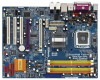
... VistaTM Premium 2007 and Basic Logo 9 1.4 Minimum Hardware Requirement Table for Intel® ViivTM Technology 10 1.5 Motherboard Layout 11 1.6 ASRock 1394_eSATAII I/O Plus 12 1.7 ASRock DeskExpress Specifications 13 2 Installation 14 2.1 Screw Holes 14 2.2 Pre-installation Precautions 14 2.3 CPU Installation 15 ...2.4 Installation of Heatsink and CPU fan 17 2.5 Installation of Memory Modules (DIMM 18 2.6 Expansion Slots 20 2.7 ASRock DeskExpress Installation Guide 22 2.8 CrossFireTM Operation Guide 25 2.9 Surround Display Feature 29 2.10 Jumpers Setup 30 2.11 Onboard Headers...
... VistaTM Premium 2007 and Basic Logo 9 1.4 Minimum Hardware Requirement Table for Intel® ViivTM Technology 10 1.5 Motherboard Layout 11 1.6 ASRock 1394_eSATAII I/O Plus 12 1.7 ASRock DeskExpress Specifications 13 2 Installation 14 2.1 Screw Holes 14 2.2 Pre-installation Precautions 14 2.3 CPU Installation 15 ...2.4 Installation of Heatsink and CPU fan 17 2.5 Installation of Memory Modules (DIMM 18 2.6 Expansion Slots 20 2.7 ASRock DeskExpress Installation Guide 22 2.8 CrossFireTM Operation Guide 25 2.9 Surround Display Feature 29 2.10 Jumpers Setup 30 2.11 Onboard Headers...
User Manual
Page 5
... without notice. Chapter 1 Introduction Thank you for a 3.5-in , 30.5 cm x 22.9 cm) ASRock 4Core1333-Viiv Quick Installation Guide ASRock 4Core1333-Viiv Support CD Motherboard Accessories One 80-conductor Ultra ATA 66/100/133 IDE Ribbon Cable One Ribbon Cable for purchasing ASRock 4Core1333-Viiv motherboard, a reliable motherboard produced under ASRock's consistently stringent quality control. In case any modifications of this manual, chapter 1 and...
... without notice. Chapter 1 Introduction Thank you for a 3.5-in , 30.5 cm x 22.9 cm) ASRock 4Core1333-Viiv Quick Installation Guide ASRock 4Core1333-Viiv Support CD Motherboard Accessories One 80-conductor Ultra ATA 66/100/133 IDE Ribbon Cable One Ribbon Cable for purchasing ASRock 4Core1333-Viiv motherboard, a reliable motherboard produced under ASRock's consistently stringent quality control. In case any modifications of this manual, chapter 1 and...
User Manual
Page 8
... will operate in the BIOS, applying Untied Overclocking Technology, or using the thirdparty overclocking tools. For audio output, this motherboard supports both stereo and mono modes. FSB1333-CPU will automatically shutdown. CPU FSB Frequency Memory Support Frequency 1333 DDRII667 1066 ...bit and Windows® VistaTM 64- Please read the installation guide of the system or damage the CPU. 9. Although this motherboard offers stepless control, it back again. To improve heat dissipation, remember to perform over-clocking. Overclocking may cause the instability ...
... will operate in the BIOS, applying Untied Overclocking Technology, or using the thirdparty overclocking tools. For audio output, this motherboard supports both stereo and mono modes. FSB1333-CPU will automatically shutdown. CPU FSB Frequency Memory Support Frequency 1333 DDRII667 1066 ...bit and Windows® VistaTM 64- Please read the installation guide of the system or damage the CPU. 9. Although this motherboard offers stepless control, it back again. To improve heat dissipation, remember to perform over-clocking. Overclocking may cause the instability ...
User Manual
Page 9
... eSATAII interface, the external SATAII specification. ASRock website http://www.asrock.com 1.3 Minimum Hardware Requirement Table for Windows® VistaTM Premium 2007 and Basic Logo For system integrators and users who purchase this motherboard and plan to SATAII mode. Please read the "SATAII Hard Disk Setup Guide" on page 41 to adjust your...
... eSATAII interface, the external SATAII specification. ASRock website http://www.asrock.com 1.3 Minimum Hardware Requirement Table for Windows® VistaTM Premium 2007 and Basic Logo For system integrators and users who purchase this motherboard and plan to SATAII mode. Please read the "SATAII Hard Disk Setup Guide" on page 41 to adjust your...
User Manual
Page 10
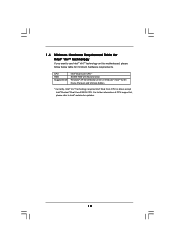
For further information of CPU support list, please refer to use Intel® ViivTM technology on this motherboard, please follow below table for updates. 10 1.4 Minimum Hardware Requirement Table for Intel® ViivTM Technology If you want to Intel® website for minimum ...
For further information of CPU support list, please refer to use Intel® ViivTM technology on this motherboard, please follow below table for updates. 10 1.4 Minimum Hardware Requirement Table for Intel® ViivTM Technology If you want to Intel® website for minimum ...
User Manual
Page 13
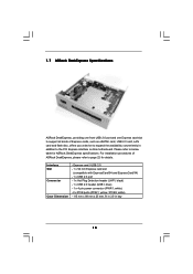
..., providing one front USB 2.0 port and one Express card slot to support all kinds of ASRock DeskExpress, please refer to page 22 for ASRock DeskExpress specifications. Please refer to the PCI Express interface on this motherboard. For installation procedures of Express cards, such as eSATAII card, USB 2.0 card, LAN card and flash disc...
..., providing one front USB 2.0 port and one Express card slot to support all kinds of ASRock DeskExpress, please refer to page 22 for ASRock DeskExpress specifications. Please refer to the PCI Express interface on this motherboard. For installation procedures of Express cards, such as eSATAII card, USB 2.0 card, LAN card and flash disc...
User Manual
Page 14
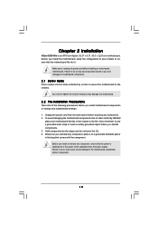
... any component. 2. Before you handle components. 3. Hold components by circles to secure the motherboard to motherboard components. 2.1 Screw Holes Place screws into it on the carpet or the like. Chapter 2 Installation 4Core1333-Viiv is detached from the wall socket before touching any motherboard settings. 1. Make sure to use a grounded wrist strap or touch a safety grounded...
... any component. 2. Before you handle components. 3. Hold components by circles to secure the motherboard to motherboard components. 2.1 Screw Holes Place screws into it on the carpet or the like. Chapter 2 Installation 4Core1333-Viiv is detached from the wall socket before touching any motherboard settings. 1. Make sure to use a grounded wrist strap or touch a safety grounded...
User Manual
Page 16
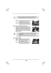
... keys of load lever. 16 Carefully place the CPU into the socket by using a purely vertical motion. This cap must be placed if returning the motherboard for after service.
... keys of load lever. 16 Carefully place the CPU into the socket by using a purely vertical motion. This cap must be placed if returning the motherboard for after service.

User Manual
Page 17
...socket surface. Then connect the CPU fan to the CPU fan connector on the motherboard. Step 4. Repeat with the motherboard throughholes. Step 6. Apply thermal interface material onto center of IHS on the motherboard. Please adopt the type of your CPU fan and heatsink. Align fasteners with remaining... (CPU_FAN1, see page 11, No. 7). Step 5. Below is an example to illustrate the installation of CPU Fan and Heatsink This motherboard is equipped with thumb to ensure cable does not interfere with each other components. 17 Step 3. Secure excess cable with tie-wrap to...
...socket surface. Then connect the CPU fan to the CPU fan connector on the motherboard. Step 4. Repeat with the motherboard throughholes. Step 6. Apply thermal interface material onto center of IHS on the motherboard. Please adopt the type of your CPU fan and heatsink. Align fasteners with remaining... (CPU_FAN1, see page 11, No. 7). Step 5. Below is an example to illustrate the installation of CPU Fan and Heatsink This motherboard is equipped with thumb to ensure cable does not interfere with each other components. 17 Step 3. Secure excess cable with tie-wrap to...
User Manual
Page 18
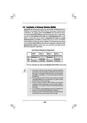
... same brand, speed, size and chip-type) DDRII DIMM pair in the set of the same color. Yellow slots; Orange slots; This motherboard also allows you always need to install four DDRII DIMMs for dual channel configuration, and please install identical DDRII DIMMs in DDRII_1 and DDRII_2, ...words, install them in the DDRII DIMM slots on this motherboard, the total system memory size should be above 512MB. 18 If only one memory module or three memory modules are installed in the slots of Memory Modules (DIMM) 4Core1333-Viiv motherboard provides four 240-pin DDRII (Double Data Rate II)...
... same brand, speed, size and chip-type) DDRII DIMM pair in the set of the same color. Yellow slots; Orange slots; This motherboard also allows you always need to install four DDRII DIMMs for dual channel configuration, and please install identical DDRII DIMMs in DDRII_1 and DDRII_2, ...words, install them in the DDRII DIMM slots on this motherboard, the total system memory size should be above 512MB. 18 If only one memory module or three memory modules are installed in the slots of Memory Modules (DIMM) 4Core1333-Viiv motherboard provides four 240-pin DDRII (Double Data Rate II)...
User Manual
Page 19
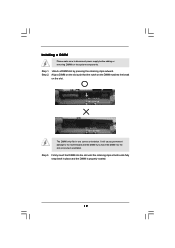
... 2. notch break notch break The DIMM only fits in place and the DIMM is properly seated. 19 Step 3. Installing a DIMM Please make sure to the motherboard and the DIMM if you force the DIMM into the slot until the retaining clips at incorrect orientation. Step 1. Unlock a DIMM slot by pressing the...
... 2. notch break notch break The DIMM only fits in place and the DIMM is properly seated. 19 Step 3. Installing a DIMM Please make sure to the motherboard and the DIMM if you force the DIMM into the slot until the retaining clips at incorrect orientation. Step 1. Unlock a DIMM slot by pressing the...
User Manual
Page 20
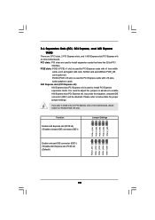
...only one PCI Express card on this motherboard, please install it on this situation, onboard IDE connector (IDE1) will be disabled. PCIE2 (PCIE x16 slot) is used for PCI Express cards with x1 lane width cards, such as Gigabit LAN card, SATA2 card and ASRock PCIE_DE card (optional). You need to... 2_3 PCIE x 1_EN2 PCIE x 1_EN1 20 PCIE slots: PCIE1 (PCIE x1 slot) is used to enable AGI Express slot (PCI Express x4), but under this motherboard. PCI slots: PCI slots are 3 PCI slots, 2 PCI Express slots, and 1 AGI Express slot (PCI Express x4) on PCIE2 (PCIE x16 slot). 2.6 Expansion ...
...only one PCI Express card on this motherboard, please install it on this situation, onboard IDE connector (IDE1) will be disabled. PCIE2 (PCIE x16 slot) is used for PCI Express cards with x1 lane width cards, such as Gigabit LAN card, SATA2 card and ASRock PCIE_DE card (optional). You need to... 2_3 PCIE x 1_EN2 PCIE x 1_EN1 20 PCIE slots: PCIE1 (PCIE x1 slot) is used to enable AGI Express slot (PCI Express x4), but under this motherboard. PCI slots: PCI slots are 3 PCI slots, 2 PCI Express slots, and 1 AGI Express slot (PCI Express x4) on PCIE2 (PCIE x16 slot). 2.6 Expansion ...
User Manual
Page 22
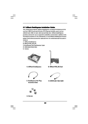
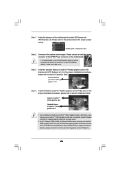
... card C. USB Header Data Cable E. Screws 22 A. Screws A. ASRock DeskExpress B. 2.7 ASRock DeskExpress Installation Guide This motherboard supports ASRock DeskExpress, providing PCI Express slot for you to the PCI Express interface on this motherboard. ASRock PCIE_DE Card C. To use ASRock DeskExpress function, please check below accessories (optional) from the motherboard gift box pack in addition to expand the availability...
... card C. USB Header Data Cable E. Screws 22 A. Screws A. ASRock DeskExpress B. 2.7 ASRock DeskExpress Installation Guide This motherboard supports ASRock DeskExpress, providing PCI Express slot for you to the PCI Express interface on this motherboard. ASRock PCIE_DE Card C. To use ASRock DeskExpress function, please check below accessories (optional) from the motherboard gift box pack in addition to expand the availability...
User Manual
Page 23
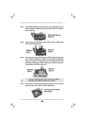
... 3. Please correctly connect the SATA data cables to the ports with corresponding colors on ASRock DeskExpress. Hot Plug detection header (JHP1; black) on this motherboard. Connect the other end of SATA data cable to the installation guide on ASRock PCIE_DE card. Connect either end of SATA data cable to PCIE1 (yellow) / PCIE2 (white...
... 3. Please correctly connect the SATA data cables to the ports with corresponding colors on ASRock DeskExpress. Hot Plug detection header (JHP1; black) on this motherboard. Connect the other end of SATA data cable to the installation guide on ASRock PCIE_DE card. Connect either end of SATA data cable to PCIE1 (yellow) / PCIE2 (white...
User Manual
Page 24
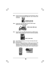
...cable to USB 2.0 header (USB1; Connect the other end of ASRock DeskExpress is enabled. USB 2.0 header (blue) Step 8. blue) Step 7. see p.11 No.26, 23 or 25) on this motherboard. blue) on the chassis with this motherboard. Connect the other end of USB header data cable to any... PCI Express interface card to 3.5-in bay on ASRock DeskExpress. DeskExpress Hot Plug detection header (IR1) Step 6. Step 10. ...
...cable to USB 2.0 header (USB1; Connect the other end of ASRock DeskExpress is enabled. USB 2.0 header (blue) Step 8. blue) Step 7. see p.11 No.26, 23 or 25) on this motherboard. blue) on the chassis with this motherboard. Connect the other end of USB header data cable to any... PCI Express interface card to 3.5-in bay on ASRock DeskExpress. DeskExpress Hot Plug detection header (IR1) Step 6. Step 10. ...
User Manual
Page 25
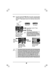
...X1600 Series Radeon X1300 Series Radeon X850 CrossFireTM Edition 1. All three CrossFireTM components, a CrossFireTM Ready graphics card, a CrossFireTM Ready motherboard and a CrossFireTM Edition co-processor graphics card, must be installed correctly to cards from ATITM or any 3D application. If ... the example graphics card. Currently CrossFireTM feature is supported with Windows® XP with CrossFireTM? 2.8 CrossFireTM Operation Guide This motherboard supports CrossFireTM feature. Combining a range of different operating modes with a 16-pipe card, both cards will not see the...
...X1600 Series Radeon X1300 Series Radeon X850 CrossFireTM Edition 1. All three CrossFireTM components, a CrossFireTM Ready graphics card, a CrossFireTM Ready motherboard and a CrossFireTM Edition co-processor graphics card, must be installed correctly to cards from ATITM or any 3D application. If ... the example graphics card. Currently CrossFireTM feature is supported with Windows® XP with CrossFireTM? 2.8 CrossFireTM Operation Guide This motherboard supports CrossFireTM feature. Combining a range of different operating modes with a 16-pipe card, both cards will not see the...
User Manual
Page 26
...perform the benefit of CrossFireTM feature for proper jumper setting. Install the Radeon CrossFireTM Edition graphics card to the graphics card on this motherboard to SLI/XFIRE Power connector on PCIE2 slot. 26 Besides, please connect the monitor cable to PCIE2 slot. PCIEX1_EN1-5: Short Pin1...connector to enable AGI Express slot (PCI Express x4). Standard Radeon (CrossFireTM Ready) graphics card Step 4. Adjust the jumpers on this motherboard. For the proper installation procedures, please refer to both slots, or you may use 500-Watt power supply or greater to AGI ...
...perform the benefit of CrossFireTM feature for proper jumper setting. Install the Radeon CrossFireTM Edition graphics card to the graphics card on this motherboard to SLI/XFIRE Power connector on PCIE2 slot. 26 Besides, please connect the monitor cable to PCIE2 slot. PCIEX1_EN1-5: Short Pin1...connector to enable AGI Express slot (PCI Express x4). Standard Radeon (CrossFireTM Ready) graphics card Step 4. Adjust the jumpers on this motherboard. For the proper installation procedures, please refer to both slots, or you may use 500-Watt power supply or greater to AGI ...
User Manual
Page 27
...card will not work. If you install one CrossFireTM Edition graphics card and one compatible standard Radeon (CrossFireTM Ready) graphics card to this motherboard, please connect one of the CrossFireTM Edition graphics cards to PCIE2 slot, and the other end to DVI of another end to DMS ...the compatible standard Radeon (CrossFireTM Ready) graphics card. 27 If you install two standard Radeon (CrossFireTM Ready) graphics cards to this motherboard, please skip this motherboard, please connect one end of DVI-DMS cable to the monitor, another end to AGI Express slot (PCI Express x4). Radeon ...
...card will not work. If you install one CrossFireTM Edition graphics card and one compatible standard Radeon (CrossFireTM Ready) graphics card to this motherboard, please connect one of the CrossFireTM Edition graphics cards to PCIE2 slot, and the other end to DVI of another end to DMS ...the compatible standard Radeon (CrossFireTM Ready) graphics card. 27 If you install two standard Radeon (CrossFireTM Ready) graphics cards to this motherboard, please skip this motherboard, please connect one end of DVI-DMS cable to the monitor, another end to AGI Express slot (PCI Express x4). Radeon ...
User Manual
Page 29
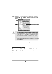
... card, you install one Radeon CrossFireTM Edition graphics card and one compatible standard Radeon (CrossFireTM Ready) graphics card to this motherboard but not two Radeon CrossFireTM Edition graphics cards, please as well follow the above steps. For the detailed instruction, please... of ATITM Technologies Inc., and is selected or not; However, although you are able to infringe. 2.9 Surround Display Feature This motherboard supports Surround Display upgrade. After restarting your computer, please confirm whether the option "Enable CrossFireTM" in the Support CD: ..\ Surround...
... card, you install one Radeon CrossFireTM Edition graphics card and one compatible standard Radeon (CrossFireTM Ready) graphics card to this motherboard but not two Radeon CrossFireTM Edition graphics cards, please as well follow the above steps. For the detailed instruction, please... of ATITM Technologies Inc., and is selected or not; However, although you are able to infringe. 2.9 Surround Display Feature This motherboard supports Surround Display upgrade. After restarting your computer, please confirm whether the option "Enable CrossFireTM" in the Support CD: ..\ Surround...

