User Manual
Page 2
...transcribed, transmitted, or translated in any language, in the manual or product. With respect to the contents of this manual, ASRock does not provide warranty of any kind, either expressed or implied, including but not limited to the following two conditions: ...(1) this device may not cause harmful interference, and (2) this motherboard contains Perchlorate, a toxic substance controlled in Perchlorate Best Management Practices (BMP) regulations passed by ASRock. In no responsibility for identification or explanation and to the owners' benefit, without intent...
...transcribed, transmitted, or translated in any language, in the manual or product. With respect to the contents of this manual, ASRock does not provide warranty of any kind, either expressed or implied, including but not limited to the following two conditions: ...(1) this device may not cause harmful interference, and (2) this motherboard contains Perchlorate, a toxic substance controlled in Perchlorate Best Management Practices (BMP) regulations passed by ASRock. In no responsibility for identification or explanation and to the owners' benefit, without intent...

User Manual
Page 3
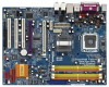
... VistaTM Premium 2007 and Basic Logo 9 1.4 Minimum Hardware Requirement Table for Intel® ViivTM Technology 10 1.5 Motherboard Layout 11 1.6 ASRock 1394_eSATAII I/O Plus 12 1.7 ASRock DeskExpress Specifications 13 2 Installation 14 2.1 Screw Holes 14 2.2 Pre-installation Precautions 14 2.3 CPU Installation 15 ...2.4 Installation of Heatsink and CPU fan 17 2.5 Installation of Memory Modules (DIMM 18 2.6 Expansion Slots 20 2.7 ASRock DeskExpress Installation Guide 22 2.8 CrossFireTM Operation Guide 25 2.9 Surround Display Feature 29 2.10 Jumpers Setup 30 2.11 Onboard Headers...
... VistaTM Premium 2007 and Basic Logo 9 1.4 Minimum Hardware Requirement Table for Intel® ViivTM Technology 10 1.5 Motherboard Layout 11 1.6 ASRock 1394_eSATAII I/O Plus 12 1.7 ASRock DeskExpress Specifications 13 2 Installation 14 2.1 Screw Holes 14 2.2 Pre-installation Precautions 14 2.3 CPU Installation 15 ...2.4 Installation of Heatsink and CPU fan 17 2.5 Installation of Memory Modules (DIMM 18 2.6 Expansion Slots 20 2.7 ASRock DeskExpress Installation Guide 22 2.8 CrossFireTM Operation Guide 25 2.9 Surround Display Feature 29 2.10 Jumpers Setup 30 2.11 Onboard Headers...
User Manual
Page 5
.... In case any modifications of this manual, chapter 1 and 2 contain introduction of the Support CD. Chapter 1 Introduction Thank you for a 3.5-in , 30.5 cm x 22.9 cm) ASRock 4Core1333-Viiv Quick Installation Guide ASRock 4Core1333-Viiv Support CD Motherboard Accessories One 80-conductor Ultra ATA 66/100/133 IDE Ribbon Cable One Ribbon Cable for purchasing...
.... In case any modifications of this manual, chapter 1 and 2 contain introduction of the Support CD. Chapter 1 Introduction Thank you for a 3.5-in , 30.5 cm x 22.9 cm) ASRock 4Core1333-Viiv Quick Installation Guide ASRock 4Core1333-Viiv Support CD Motherboard Accessories One 80-conductor Ultra ATA 66/100/133 IDE Ribbon Cable One Ribbon Cable for purchasing...
User Manual
Page 8
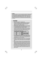
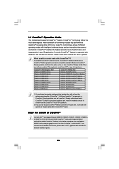
...Windows® VistaTM Home Premium and Ultimate Edition. To improve heat dissipation, remember to perform over-clocking. For audio output, this motherboard supports both stereo and mono modes. It should be less than the recommended CPU bus frequencies may cause the instability of "Hyper... Threading Technology", please check page 55. 4. This motherboard supports Untied Overclocking Technology. Please check the table below for details. 5. For Windows® XP 64-bit and Windows® VistaTM...
...Windows® VistaTM Home Premium and Ultimate Edition. To improve heat dissipation, remember to perform over-clocking. For audio output, this motherboard supports both stereo and mono modes. It should be less than the recommended CPU bus frequencies may cause the instability of "Hyper... Threading Technology", please check page 55. 4. This motherboard supports Untied Overclocking Technology. Please check the table below for details. 5. For Windows® XP 64-bit and Windows® VistaTM...
User Manual
Page 9
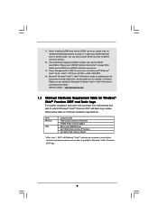
Please visit our website for minimum hardware requirements. ASRock website http://www.asrock.com 1.3 Minimum Hardware Requirement Table for Windows® VistaTM Premium 2007 and Basic Logo For system integrators and users who purchase this motherboard and plan to SATAII mode. You can also...Basic logo, please follow below table for Microsoft® Windows® VistaTM / VistaTM 64-bit driver and related information. This motherboard supports eSATAII interface, the external SATAII specification. Microsoft® Windows® VistaTM / VistaTM 64-bit driver keeps on page 38 ...
Please visit our website for minimum hardware requirements. ASRock website http://www.asrock.com 1.3 Minimum Hardware Requirement Table for Windows® VistaTM Premium 2007 and Basic Logo For system integrators and users who purchase this motherboard and plan to SATAII mode. You can also...Basic logo, please follow below table for Microsoft® Windows® VistaTM / VistaTM 64-bit driver and related information. This motherboard supports eSATAII interface, the external SATAII specification. Microsoft® Windows® VistaTM / VistaTM 64-bit driver keeps on page 38 ...
User Manual
Page 10
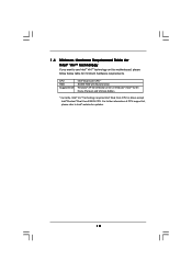
... Intel® Pentium® Dual Core E2XXX CPU. For further information of CPU support list, please refer to use Intel® ViivTM technology on this motherboard, please follow below table for updates. 10
... Intel® Pentium® Dual Core E2XXX CPU. For further information of CPU support list, please refer to use Intel® ViivTM technology on this motherboard, please follow below table for updates. 10
User Manual
Page 13
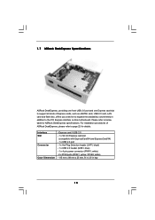
... mm, fit in 3.5-in addition to the PCI Express interface on this motherboard. 1.7 ASRock DeskExpress Specifications ASRock DeskExpress, providing one front USB 2.0 port and one Express card slot to support all kinds of ASRock DeskExpress, please refer to page 22 for ASRock DeskExpress specifications. For installation procedures of Express cards, such as eSATAII card, USB...
... mm, fit in 3.5-in addition to the PCI Express interface on this motherboard. 1.7 ASRock DeskExpress Specifications ASRock DeskExpress, providing one front USB 2.0 port and one Express card slot to support all kinds of ASRock DeskExpress, please refer to page 22 for ASRock DeskExpress specifications. For installation procedures of Express cards, such as eSATAII card, USB...
User Manual
Page 14
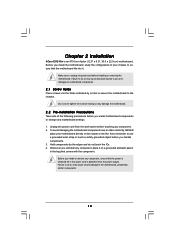
... physical injuries to you install or remove any component, place it . Whenever you install motherboard components or change any component. 2. Failure to do not touch the ICs. 4. Chapter 2 Installation 4Core1333-Viiv is detached from the wall socket before touching any motherboard settings. 1. Before you handle components. 3. Doing so may cause severe damage to the...
... physical injuries to you install or remove any component, place it . Whenever you install motherboard components or change any component. 2. Failure to do not touch the ICs. 4. Chapter 2 Installation 4Core1333-Viiv is detached from the wall socket before touching any motherboard settings. 1. Before you handle components. 3. Doing so may cause severe damage to the...
User Manual
Page 16
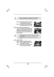
... the CPU into the socket by using a purely vertical motion. Rotate the load plate onto the IHS. This cap must be placed if returning the motherboard for after service. Step 2-3. Step 2-4. Step 3. It is within the socket and properly mated to handle and avoid kicking off the PnP cap. 2. Step 4-2. Secure...
... the CPU into the socket by using a purely vertical motion. Rotate the load plate onto the IHS. This cap must be placed if returning the motherboard for after service. Step 2-3. Step 2-4. Step 3. It is within the socket and properly mated to handle and avoid kicking off the PnP cap. 2. Step 4-2. Secure...

User Manual
Page 17
... the CPU and the heatsink to improve heat dissipation. For proper installation, please kindly refer to the instruction manuals of IHS on the motherboard. Step 3. Repeat with thumb to install and lock. Step 6. Step 1. Apply thermal interface material onto center of your CPU fan and... heatsink. Step 4. Align fasteners with the motherboard throughholes. Secure excess cable with tie-wrap to ensure cable does not interfere with fan operation or contact other . Before you installed the...
... the CPU and the heatsink to improve heat dissipation. For proper installation, please kindly refer to the instruction manuals of IHS on the motherboard. Step 3. Repeat with thumb to install and lock. Step 6. Step 1. Apply thermal interface material onto center of your CPU fan and... heatsink. Step 4. Align fasteners with the motherboard throughholes. Secure excess cable with tie-wrap to ensure cable does not interfere with fan operation or contact other . Before you installed the...
User Manual
Page 18
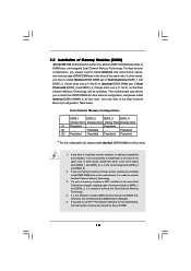
...for optimal compatibility and reliability, it is not allowed to install identical DDRII DIMM pair in the slots of Memory Modules (DIMM) 4Core1333-Viiv motherboard provides four 240-pin DDRII (Double Data Rate II) DIMM slots, and supports Dual Channel Memory Technology. Dual Channel Memory Configurations ... DDRII slot; 2.5 Installation of the same color. In other words, you plan to use ATITM PCI Express VGA card on this motherboard, it is NOT installed in the same Dual Channel, for dual channel configuration, and please install identical DDRII DIMMs in all four slots...
...for optimal compatibility and reliability, it is not allowed to install identical DDRII DIMM pair in the slots of Memory Modules (DIMM) 4Core1333-Viiv motherboard provides four 240-pin DDRII (Double Data Rate II) DIMM slots, and supports Dual Channel Memory Technology. Dual Channel Memory Configurations ... DDRII slot; 2.5 Installation of the same color. In other words, you plan to use ATITM PCI Express VGA card on this motherboard, it is NOT installed in the same Dual Channel, for dual channel configuration, and please install identical DDRII DIMMs in all four slots...
User Manual
Page 19
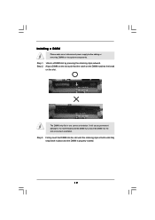
... 1. Align a DIMM on the slot such that the notch on the DIMM matches the break on the slot. Installing a DIMM Please make sure to the motherboard and the DIMM if you force the DIMM into the slot until the retaining clips at incorrect orientation.
... 1. Align a DIMM on the slot such that the notch on the DIMM matches the break on the slot. Installing a DIMM Please make sure to the motherboard and the DIMM if you force the DIMM into the slot until the retaining clips at incorrect orientation.
User Manual
Page 20
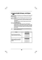
.... PCIE slots: PCIE1 (PCIE x1 slot) is used for PCI Express cards with x1 lane width cards, such as Gigabit LAN card, SATA2 card and ASRock PCIE_DE card (optional). AGI Express slot (PCI Express x4): AGI Express slot (PCI Express x4) is used to install only one PCI Express card on... this motherboard, please install it on this situation, onboard IDE connector (IDE1) will be disabled. If you plan to install PCI Express expansion cards. PCIE2 (PCIE x16...
.... PCIE slots: PCIE1 (PCIE x1 slot) is used for PCI Express cards with x1 lane width cards, such as Gigabit LAN card, SATA2 card and ASRock PCIE_DE card (optional). AGI Express slot (PCI Express x4): AGI Express slot (PCI Express x4) is used to install only one PCI Express card on... this motherboard, please install it on this situation, onboard IDE connector (IDE1) will be disabled. If you plan to install PCI Express expansion cards. PCIE2 (PCIE x16...
User Manual
Page 22
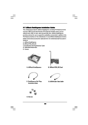
... addition to expand the availability conveniently in advance. ASRock DeskExpress B. ASRock PCIE_DE card C. DeskExpress Hot Plug Detection Cable D. ASRock PCIE_DE Card C. 2.7 ASRock DeskExpress Installation Guide This motherboard supports ASRock DeskExpress, providing PCI Express slot for you to the PCI Express interface on this motherboard. USB Header Data Cable E. Screws 22 ASRock DeskExpress provides a device for one front USB...
... addition to expand the availability conveniently in advance. ASRock DeskExpress B. ASRock PCIE_DE card C. DeskExpress Hot Plug Detection Cable D. ASRock PCIE_DE Card C. 2.7 ASRock DeskExpress Installation Guide This motherboard supports ASRock DeskExpress, providing PCI Express slot for you to the PCI Express interface on this motherboard. USB Header Data Cable E. Screws 22 ASRock DeskExpress provides a device for one front USB...
User Manual
Page 23
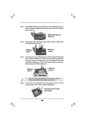
...not function. Hot Plug detection header (JHP1; Connect either end of SATA data cable to PCIE1 (yellow) / PCIE2 (white) port on ASRock PCIE_DE card and ASRock DeskExpress. (PCIE1 (yellow) port to PCIE1 (yellow) port; PCIE2 (white) port to PCIE2 (white) port.) PCIE2 port (white) ...Step 2. Please correctly connect the SATA data cables to PCIE1 slot on ASRock DeskExpress. black) on this motherboard. Install ASRock PCIE_DE card to the ports with corresponding colors on ASRock PCIE_DE card. Connect the other end of ASRock PCIE_DE card, please refer to PCIE1 (yellow) / PCIE2 (white) ...
...not function. Hot Plug detection header (JHP1; Connect either end of SATA data cable to PCIE1 (yellow) / PCIE2 (white) port on ASRock PCIE_DE card and ASRock DeskExpress. (PCIE1 (yellow) port to PCIE1 (yellow) port; PCIE2 (white) port to PCIE2 (white) port.) PCIE2 port (white) ...Step 2. Please correctly connect the SATA data cables to PCIE1 slot on ASRock DeskExpress. black) on this motherboard. Install ASRock PCIE_DE card to the ports with corresponding colors on ASRock PCIE_DE card. Connect the other end of ASRock PCIE_DE card, please refer to PCIE1 (yellow) / PCIE2 (white) ...
User Manual
Page 24
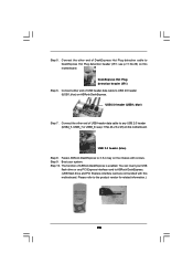
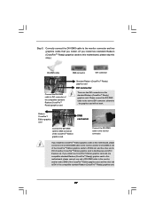
Step 5. see p.11 No.26, 23 or 25) on the chassis with this motherboard. blue) on this motherboard. see p.11 No.29) on ASRock DeskExpress. Please refer to 3.5-in bay on this motherboard. DeskExpress Hot Plug detection header (IR1) Step 6. Boot your USB flash drive or any USB... 2.0 header (USB4_5, USB6_7 or USB8_9; Connect either end of ASRock DeskExpress is enabled. The function of USB header data cable to ...
Step 5. see p.11 No.26, 23 or 25) on the chassis with this motherboard. blue) on this motherboard. see p.11 No.29) on ASRock DeskExpress. Please refer to 3.5-in bay on this motherboard. DeskExpress Hot Plug detection header (IR1) Step 6. Boot your USB flash drive or any USB... 2.0 header (USB4_5, USB6_7 or USB8_9; Connect either end of ASRock DeskExpress is enabled. The function of USB header data cable to ...
User Manual
Page 25
... a 16-pipe card, both cards will operate as the example graphics card. A complete CrossFireTM system requires a CrossFireTM Ready motherboard, a CrossFireTM Edition graphics card and a compatible standard Radeon (CrossFireTM Ready) graphics card from the same series, or two ... of different operating modes with Service Pack 2. 2.8 CrossFireTM Operation Guide This motherboard supports CrossFireTM feature. All three CrossFireTM components, a CrossFireTM Ready graphics card, a CrossFireTM Ready motherboard and a CrossFireTM Edition co-processor graphics card, must be installed correctly to...
... a 16-pipe card, both cards will operate as the example graphics card. A complete CrossFireTM system requires a CrossFireTM Ready motherboard, a CrossFireTM Edition graphics card and a compatible standard Radeon (CrossFireTM Ready) graphics card from the same series, or two ... of different operating modes with Service Pack 2. 2.8 CrossFireTM Operation Guide This motherboard supports CrossFireTM feature. All three CrossFireTM components, a CrossFireTM Ready graphics card, a CrossFireTM Ready motherboard and a CrossFireTM Edition co-processor graphics card, must be installed correctly to...
User Manual
Page 26
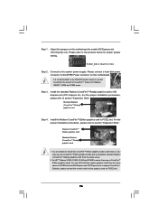
... supply or greater to enable AGI Express slot (PCI Express x4). Besides, please connect the monitor cable to the graphics card on this motherboard to perform the benefit of CrossFireTM feature for proper jumper setting. Connect to section "Expansion Slots". Step 3. Standard Radeon (CrossFireTM Ready) ... use one CrossFireTM Edition graphics cards and a compatible standard Radeon (CrossFireTM Ready) graphics card from the same series on this motherboard. Step 1. Adjust the jumpers on PCIE2 slot and AGI Express slot (PCI Express x4) to AGI Express slot (PCI Express x4).
... supply or greater to enable AGI Express slot (PCI Express x4). Besides, please connect the monitor cable to the graphics card on this motherboard to perform the benefit of CrossFireTM feature for proper jumper setting. Connect to section "Expansion Slots". Step 3. Standard Radeon (CrossFireTM Ready) ... use one CrossFireTM Edition graphics cards and a compatible standard Radeon (CrossFireTM Ready) graphics card from the same series on this motherboard. Step 1. Adjust the jumpers on PCIE2 slot and AGI Express slot (PCI Express x4) to AGI Express slot (PCI Express x4).
User Manual
Page 27
... to the correct DVI connector; If you install one CrossFireTM Edition graphics card and one compatible standard Radeon (CrossFireTM Ready) graphics card to this motherboard, please connect one of the CrossFireTM Edition graphics cards to PCIE2 slot, and the other end to DVI of another end to DMS of the... the other end to AGI Express slot (PCI Express x4). If you install two standard Radeon (CrossFireTM Ready) graphics cards to this motherboard, please skip this motherboard, please connect one end of DVI-DMS cable to the monitor, another end to DMS of one end of DVI-DMS cable to the...
... to the correct DVI connector; If you install one CrossFireTM Edition graphics card and one compatible standard Radeon (CrossFireTM Ready) graphics card to this motherboard, please connect one of the CrossFireTM Edition graphics cards to PCIE2 slot, and the other end to DVI of another end to DMS of the... the other end to AGI Express slot (PCI Express x4). If you install two standard Radeon (CrossFireTM Ready) graphics cards to this motherboard, please skip this motherboard, please connect one end of DVI-DMS cable to the monitor, another end to DMS of one end of DVI-DMS cable to the...
User Manual
Page 29
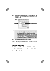
...one Radeon CrossFireTM Edition graphics card and one compatible standard Radeon (CrossFireTM Ready) graphics card to infringe. 2.9 Surround Display Feature This motherboard supports Surround Display upgrade. Step 12. After restarting your computer, please confirm whether the option "Enable CrossFireTM" in the Support ..."ATI Catalyst Control Center" is used only for identification or explanation and to the owners' benefit, without intent to this motherboard but not two Radeon CrossFireTM Edition graphics cards, please as well follow the above steps. Double-click "ATI Catalyst Control...
...one Radeon CrossFireTM Edition graphics card and one compatible standard Radeon (CrossFireTM Ready) graphics card to infringe. 2.9 Surround Display Feature This motherboard supports Surround Display upgrade. Step 12. After restarting your computer, please confirm whether the option "Enable CrossFireTM" in the Support ..."ATI Catalyst Control Center" is used only for identification or explanation and to the owners' benefit, without intent to this motherboard but not two Radeon CrossFireTM Edition graphics cards, please as well follow the above steps. Double-click "ATI Catalyst Control...

