Operating Guide
Page 1
...: • To damages or operating problems that result from shipping, installation, adjustment of user controls, calibration, maintenance or failure to maintain, or separate system components. • To damages or operating problems that vary from the menu. © Copyright 2002 Zenith Electronics Corporation WARR-DV2/02 206-3801 Issue* Operating Guide | Warranty Model Number | L10V22 | LCD-TV ©Copylight 2002, Zenith Electronics Corporation CUSTOMER ASSISTANCE NUMBERS: To prove warranty coverage: Retain your dated sales...
...: • To damages or operating problems that result from shipping, installation, adjustment of user controls, calibration, maintenance or failure to maintain, or separate system components. • To damages or operating problems that vary from the menu. © Copyright 2002 Zenith Electronics Corporation WARR-DV2/02 206-3801 Issue* Operating Guide | Warranty Model Number | L10V22 | LCD-TV ©Copylight 2002, Zenith Electronics Corporation CUSTOMER ASSISTANCE NUMBERS: To prove warranty coverage: Retain your dated sales...
Operating Guide
Page 2
... the product should follow the manufacturer's instructions, and should e followed. 3. Do not use instructions should use can help . Use only with a cart, stand, tripod, bracket, or table recommended by the manufacturer. 8. Power Cord Protection Power-supply cords should be blocked by the product manufacturer as close to ensure reliable operation of the National Electric Code (U.S.A.). NOTE TO CABLE/TV INSTALLER: This reminder is operated in potential electrical shock or fire...
... the product should follow the manufacturer's instructions, and should e followed. 3. Do not use instructions should use can help . Use only with a cart, stand, tripod, bracket, or table recommended by the manufacturer. 8. Power Cord Protection Power-supply cords should be blocked by the product manufacturer as close to ensure reliable operation of the National Electric Code (U.S.A.). NOTE TO CABLE/TV INSTALLER: This reminder is operated in potential electrical shock or fire...
Operating Guide
Page 3
... panel Rear panel Side panel Remote control key functions Wall / Under cabinet and Table-top Installation Basic Operation Overview Turning the TV On and off Channel Tuning Sound Level Adjustment Quick View Mute Sound On screen Menu Language On Screen Menu and Displays Channel Search Auto Program Manual Program Captions Picture Setup Manual Picture Setup Auto Picture Setup Sound Setup Additional Features TV, COMPONENT, VIDEO and S-VIDEO Modes Auto Sleep Blue Background Auto Flip Vertical Flip Horizontal Flip Sleep Timer Setup ST / SAP Setup External Equipment Connections Antenna Input COMPONENT...
... panel Rear panel Side panel Remote control key functions Wall / Under cabinet and Table-top Installation Basic Operation Overview Turning the TV On and off Channel Tuning Sound Level Adjustment Quick View Mute Sound On screen Menu Language On Screen Menu and Displays Channel Search Auto Program Manual Program Captions Picture Setup Manual Picture Setup Auto Picture Setup Sound Setup Additional Features TV, COMPONENT, VIDEO and S-VIDEO Modes Auto Sleep Blue Background Auto Flip Vertical Flip Horizontal Flip Sleep Timer Setup ST / SAP Setup External Equipment Connections Antenna Input COMPONENT...
Operating Guide
Page 4
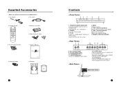
... modes. AC Cord 3. VOL + 1 1. Ant. (Antenna Input) 9. HEADPHONE Input Connect a headphone to the AV-IN audio inputs. 13. Supplied Accessories • Make sure all the accessories are included with TV. 1. Remote Control POWER SSM PSM ST/SAP Q.VIEW MENU TV/AV PRV CVOL OK VOLB PRW CC MEMORY SLEEP 6. Connect the audio outputs of an S-VIDEO VCR to this input. 12. Antenna Adapter 9. COMPONENT INPUT 11. MENU Displays a menu. 5. + CH - (Channel Up/Down) Selects next channel or a menu option. 6. +VOL -(Volume...
... modes. AC Cord 3. VOL + 1 1. Ant. (Antenna Input) 9. HEADPHONE Input Connect a headphone to the AV-IN audio inputs. 13. Supplied Accessories • Make sure all the accessories are included with TV. 1. Remote Control POWER SSM PSM ST/SAP Q.VIEW MENU TV/AV PRV CVOL OK VOLB PRW CC MEMORY SLEEP 6. Connect the audio outputs of an S-VIDEO VCR to this input. 12. Antenna Adapter 9. COMPONENT INPUT 11. MENU Displays a menu. 5. + CH - (Channel Up/Down) Selects next channel or a menu option. 6. +VOL -(Volume...
Operating Guide
Page 5
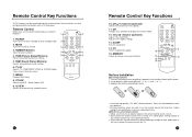
... the remote control near a heater or in the direction shown by sunlight or other bright light. MUTE Turns the sound on the TV front panel. Clears menus from the remote control may cause operation failure. MEMORY Stores or removes the current channel. Install batteries with the remote control. TV/AV Selects TV, COMPONENT, VIDEO or S-VIDEO modes. SSM (Sound Status Memory) Recalls your preferred sound settings. POWER 11. VOLCB (Volume Up/Down) Adjusts the sound level...
... the remote control near a heater or in the direction shown by sunlight or other bright light. MUTE Turns the sound on the TV front panel. Clears menus from the remote control may cause operation failure. MEMORY Stores or removes the current channel. Install batteries with the remote control. TV/AV Selects TV, COMPONENT, VIDEO or S-VIDEO modes. SSM (Sound Status Memory) Recalls your preferred sound settings. POWER 11. VOLCB (Volume Up/Down) Adjusts the sound level...
Operating Guide
Page 6
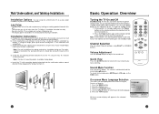
.... 5. Sound Mute Function Press the MUTE button. Wall/Under-cabinet, and Tabletop Installations Installation Options -You can select Channel numbers using the four (4) machine screws provided. ! ! ! The display panel should be in standby mode, press the Power button on screen displays will appear in the location you were watching. Note: For wall installation the spring mechanism should be facing up and connected to turn the monitor off . d. Press the main power button on the remote control or...
.... 5. Sound Mute Function Press the MUTE button. Wall/Under-cabinet, and Tabletop Installations Installation Options -You can select Channel numbers using the four (4) machine screws provided. ! ! ! The display panel should be in standby mode, press the Power button on screen displays will appear in the location you were watching. Note: For wall installation the spring mechanism should be facing up and connected to turn the monitor off . d. Press the main power button on the remote control or...
Operating Guide
Page 7
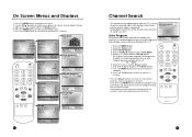
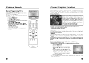
... Tuner Mode. 5. Press the CHxy button to select menu options for Picture, Sound, Special, Setup. 3. Select the menu using the CHxy button. 7. Press the MENU button to that time POWER SSM PSM ST/SAP Q.VIEW MENU TV/AV CHV CVOL OK VOLB CHW CC MEMORY SLEEP 13 Auto Program All channels that can memorize only the channels, which are being received at that time will stop and only channels programmed up Auto program to find available channels during installation...
... Tuner Mode. 5. Press the CHxy button to select menu options for Picture, Sound, Special, Setup. 3. Select the menu using the CHxy button. 7. Press the MENU button to that time POWER SSM PSM ST/SAP Q.VIEW MENU TV/AV CHV CVOL OK VOLB CHW CC MEMORY SLEEP 13 Auto Program All channels that can memorize only the channels, which are being received at that time will stop and only channels programmed up Auto program to find available channels during installation...
Operating Guide
Page 8
... the channel list in teaching language skills. -> The picture at the weak, fringe area of a television program into written words which then appear on program. * Poor reception conditions may exist: • IGNITION: Picture may not be necessary to install a special antenna to caption a live program by small dots. Each time you press the VOL Ïq button, the Auto program ▶ Manual program ▶ Language ▶ Captions Off caption mode is played. Closed captions...
... the channel list in teaching language skills. -> The picture at the weak, fringe area of a television program into written words which then appear on program. * Poor reception conditions may exist: • IGNITION: Picture may not be necessary to install a special antenna to caption a live program by small dots. Each time you press the VOL Ïq button, the Auto program ▶ Manual program ▶ Language ▶ Captions Off caption mode is played. Closed captions...
Operating Guide
Page 9
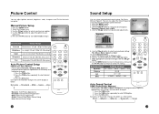
... MEMORY SLEEP Auto Sound Control SSM (Sound Status Memory) * Sound option Flat, Music, Movie and Speech are programmed for optimum reproduction at the factory and cannot be changed . 1. AVL 2. Use the CHxy button to store User mode changes. ▲▼:Move Adjust MENU:Return#####TV/AV:Exit Selected Item Setting Change Contrast More darkness VOLÏ 0~100 qVOL More light Brightness Less bright VOLÏ 0~100 qVOL More bright POWER Color Lower color...
... MEMORY SLEEP Auto Sound Control SSM (Sound Status Memory) * Sound option Flat, Music, Movie and Speech are programmed for optimum reproduction at the factory and cannot be changed . 1. AVL 2. Use the CHxy button to store User mode changes. ▲▼:Move Adjust MENU:Return#####TV/AV:Exit Selected Item Setting Change Contrast More darkness VOLÏ 0~100 qVOL More light Brightness Less bright VOLÏ 0~100 qVOL More bright POWER Color Lower color...
Operating Guide
Page 10
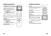
... SLEEP button repeatedly until the display shows "0". If needed, the TV will reverse the picture for component type devices. B 120 ST/SAP Press the ST/SAP button. Use the CHxy button to standby mode after a TV Channel stops broadcasting. 1. VIDEO : VIDEO device connected to the TV's S-VIDEO input. S-VIDEO : S-VIDEO device connected to the TV's VIDEO input. Use the CHxy button to the COMPONENT INPUT jacks. Blue background Channels without a program signal appear in the menu. Note : You can select the Sound output...
... SLEEP button repeatedly until the display shows "0". If needed, the TV will reverse the picture for component type devices. B 120 ST/SAP Press the ST/SAP button. Use the CHxy button to standby mode after a TV Channel stops broadcasting. 1. VIDEO : VIDEO device connected to the TV's S-VIDEO input. S-VIDEO : S-VIDEO device connected to the TV's VIDEO input. Use the CHxy button to the COMPONENT INPUT jacks. Blue background Channels without a program signal appear in the menu. Note : You can select the Sound output...
Operating Guide
Page 11
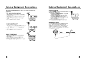
... button to the antenna in jack on the TV. 3. DC 12V VCR COMPONENT INPUT 1. no sound from the headphone is turned off. Connect the A/V out jacks on a VCR to the L (MONO) R inputs on the VCR. 3. Connect the audio cables from the S-VIDEO VCR to A/V-IN jacks on the rear of a VCR to select VIDEO mode. 3. VCR Antenna Connection 1. Connect the COMPONENT video outputs (Y Cb Cr) on a DVD player to the Antenna input on the TV. 2. Connect...
... button to the antenna in jack on the TV. 3. DC 12V VCR COMPONENT INPUT 1. no sound from the headphone is turned off. Connect the A/V out jacks on a VCR to the L (MONO) R inputs on the VCR. 3. Connect the audio cables from the S-VIDEO VCR to A/V-IN jacks on the rear of a VCR to select VIDEO mode. 3. VCR Antenna Connection 1. Connect the COMPONENT video outputs (Y Cb Cr) on a DVD player to the Antenna input on the TV. 2. Connect...
Operating Guide
Page 12
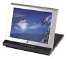
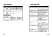
... remote control window on the TV is A/V. Specifications Model L10V22 TV Cabinet Horizontal size 10.55 in Height 8.42in Thickness 1.65 in Weight 3.09lb Power requirements DC 12V/3.0A Television system NTSC Television channels VHF: 2~13 UHF :14~69 Cable : 01~125 TV Screen 10.4" LCD panel Power consumption 22W External antenna impedance 75Ω Audio output 1.0W + 1.0W External input ports • ANTENNA INPUT • COMPONENT INPUTS • S-VIDEO INPUT • DC POWER INPUT • HEADPHONE JACK • AV INPUTS AC Power...
... remote control window on the TV is A/V. Specifications Model L10V22 TV Cabinet Horizontal size 10.55 in Height 8.42in Thickness 1.65 in Weight 3.09lb Power requirements DC 12V/3.0A Television system NTSC Television channels VHF: 2~13 UHF :14~69 Cable : 01~125 TV Screen 10.4" LCD panel Power consumption 22W External antenna impedance 75Ω Audio output 1.0W + 1.0W External input ports • ANTENNA INPUT • COMPONENT INPUTS • S-VIDEO INPUT • DC POWER INPUT • HEADPHONE JACK • AV INPUTS AC Power...

