Owner's Manual
Page 1
UA Front Surround System (CENTER SYSTEM + SUBWOOFER/SYSTEM CONTROL) YAS-71 (YAS-71CU + YAS-71SPX) OWNER'S MANUAL
UA Front Surround System (CENTER SYSTEM + SUBWOOFER/SYSTEM CONTROL) YAS-71 (YAS-71CU + YAS-71SPX) OWNER'S MANUAL
Owner's Manual
Page 2
A polarized plug has two blades with the apparatus. If the provided plug does not fit into the apparatus, the apparatus has been exposed to qualified service personnel. REFER SERVICING TO QUALIFIED SERVICE PERSONNEL. • Explanation of the polarized or grounding-type plug. The exclamation point within the product's enclosure that may be connected to the grounding system of important operating and maintenance (servicing) instructions in the space below. When a cart is used, use this Owner's Manual in any heat sources such as close to the presence of the building, as ...
A polarized plug has two blades with the apparatus. If the provided plug does not fit into the apparatus, the apparatus has been exposed to qualified service personnel. REFER SERVICING TO QUALIFIED SERVICE PERSONNEL. • Explanation of the polarized or grounding-type plug. The exclamation point within the product's enclosure that may be connected to the grounding system of important operating and maintenance (servicing) instructions in the space below. When a cart is used, use this Owner's Manual in any heat sources such as close to the presence of the building, as ...
Owner's Manual
Page 3
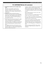
... residential environment will not occur in this type of product. In the case of interference, which can not locate the appropriate retailer, please contact Yamaha Electronics Corp., U.S.A. 6660 Orangethorpe Ave., Buena Park, CA 90620. If you can be the source of radio or TV interference, relocate/reorient the...DO NOT MODIFY THIS UNIT! Utilize power outlets that is 300 ohm ribbon lead, change the lead-in to those products distributed by Yamaha may cause interference harmful to be determined by using one of other electronic devices. Modifications not expressly approved by...
... residential environment will not occur in this type of product. In the case of interference, which can not locate the appropriate retailer, please contact Yamaha Electronics Corp., U.S.A. 6660 Orangethorpe Ave., Buena Park, CA 90620. If you can be the source of radio or TV interference, relocate/reorient the...DO NOT MODIFY THIS UNIT! Utilize power outlets that is 300 ohm ribbon lead, change the lead-in to those products distributed by Yamaha may cause interference harmful to be determined by using one of other electronic devices. Modifications not expressly approved by...
Owner's Manual
Page 4
...distortion - On the top of power. Containers with a humidifier) to prevent condensation inside this unit rises, it is too late, Yamaha and the Electronic Industries Association's Consumer Electronics Group recommend you to avoid prolonged exposure from the AC power source even if you to... this unit, and/or personal injury. - Yamaha will form when the surrounding temperature changes suddenly. Disconnect the power supply cable from direct sunlight, heat sources, vibration, dust, moisture,...
...distortion - On the top of power. Containers with a humidifier) to prevent condensation inside this unit rises, it is too late, Yamaha and the Electronic Industries Association's Consumer Electronics Group recommend you to avoid prolonged exposure from the AC power source even if you to... this unit, and/or personal injury. - Yamaha will form when the surrounding temperature changes suddenly. Disconnect the power supply cable from direct sunlight, heat sources, vibration, dust, moisture,...
Owner's Manual
Page 5
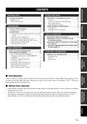
...YAS-71SPX). OTHER FUNCTIONS USEFUL OPERATION ADDITIONAL INFORMATION English 1 En INTRODUCTION PREPARATION BASIC OPERATION CONTENTS INTRODUCTION GETTING STARTED 2 Supplied parts 2 Controls and functions 3 PREPARATION PLACING THIS SYSTEM 8 Placing the center system 8 CONNECTION 11 Connecting the center system and the subwoofer/system control 11 Connecting external components 12 Connecting the Yamaha... iPod universal dock 14 Connecting the Yamaha Bluetooth audio receiver ...... 14 Connecting the indoor FM...
...YAS-71SPX). OTHER FUNCTIONS USEFUL OPERATION ADDITIONAL INFORMATION English 1 En INTRODUCTION PREPARATION BASIC OPERATION CONTENTS INTRODUCTION GETTING STARTED 2 Supplied parts 2 Controls and functions 3 PREPARATION PLACING THIS SYSTEM 8 Placing the center system 8 CONNECTION 11 Connecting the center system and the subwoofer/system control 11 Connecting external components 12 Connecting the Yamaha... iPod universal dock 14 Connecting the Yamaha Bluetooth audio receiver ...... 14 Connecting the indoor FM...
Owner's Manual
Page 6
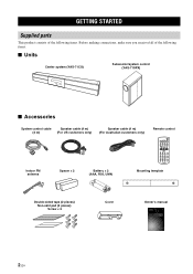
... This product consists of the following items. Before making connections, make sure you received all of the following items. ■ Units Center system (YAS-71CU) Subwoofer/system control (YAS-71SPX) ■ Accessories System control cable Speaker cable (4 m) (4 m) (For US customers only) Speaker cable (4 m) (For Australian customers only) Remote control ...Mounting template Double-sided tape (2 pieces) Non-skid pad (2 pieces) Screw × 6 Cover Owner's manual UA Front Surround System (CENTER SYSTEM + SUBWOOFER/SYSTEM CONTROL) YAS-71 (YAS-71CU + YAS-71SPX) OWNER'S MANUAL 2 En
... This product consists of the following items. Before making connections, make sure you received all of the following items. ■ Units Center system (YAS-71CU) Subwoofer/system control (YAS-71SPX) ■ Accessories System control cable Speaker cable (4 m) (4 m) (For US customers only) Speaker cable (4 m) (For Australian customers only) Remote control ...Mounting template Double-sided tape (2 pieces) Non-skid pad (2 pieces) Screw × 6 Cover Owner's manual UA Front Surround System (CENTER SYSTEM + SUBWOOFER/SYSTEM CONTROL) YAS-71 (YAS-71CU + YAS-71SPX) OWNER'S MANUAL 2 En
Owner's Manual
Page 7
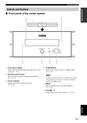
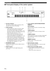
INTRODUCTION Controls and functions ■ Front panel of the center system GETTING STARTED 1 Front panel display Shows information about the operational status of the system. (☞ P. 4) 2 Remote control sensor Receives infrared signals from the remote control. (☞ P. 5, 7) 3 Power indicator Lights up when the system is turned on. (☞ P. 16) 4 STANDBY/ON Turns on the system, or sets it to standby mode. (☞ P. 16) Note A small amount of electricity is consumed to receive the infrared signal from the remote control even when the system is in standby mode. 5 INPUT Selects ...
INTRODUCTION Controls and functions ■ Front panel of the center system GETTING STARTED 1 Front panel display Shows information about the operational status of the system. (☞ P. 4) 2 Remote control sensor Receives infrared signals from the remote control. (☞ P. 5, 7) 3 Power indicator Lights up when the system is turned on. (☞ P. 16) 4 STANDBY/ON Turns on the system, or sets it to standby mode. (☞ P. 16) Note A small amount of electricity is consumed to receive the infrared signal from the remote control even when the system is in standby mode. 5 INPUT Selects ...
Owner's Manual
Page 8
...of the decoders of the system is functioning. 2 DOCK indicator • Lights up when the system is receiving a signal from an iPod stationed in the Yamaha iPod universal dock (such as YDS-10 or YDS-11, sold separately) connected to the DOCK terminal of the subwoofer/system control. (☞ P. 27) ...• Lights up while the Yamaha Bluetooth audio receiver (such as YBA-10, sold separately) is connected to the Bluetooth component. (☞ P. 29) • Flashes while the connected...
...of the decoders of the system is functioning. 2 DOCK indicator • Lights up when the system is receiving a signal from an iPod stationed in the Yamaha iPod universal dock (such as YDS-10 or YDS-11, sold separately) connected to the DOCK terminal of the subwoofer/system control. (☞ P. 27) ...• Lights up while the Yamaha Bluetooth audio receiver (such as YBA-10, sold separately) is connected to the Bluetooth component. (☞ P. 29) • Flashes while the connected...
Owner's Manual
Page 9
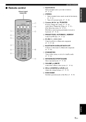
INTRODUCTION ■ Remote control Infrared signal transmitter GETTING STARTED 1 Input buttons Select an input source you want to listen to. (☞ P. 16) 2 STEREO • Turns extended stereo mode on and off alternately. (☞ P. 21) • Turns off surround mode. (☞ P. 18) 3 Cursors (W / X / S / T)/ENTER Position: Change the setting. (☞ P. 19) Audio delay: Change the setting. (☞ P. 31) iPod: Move the cursor. (☞ P. 27) FM: Move a preset group and number forward or backward. (☞ P. 22) 4 PRESET/TUNE, AUTO/MAN'L, MEMORY Control an FM tuner. (☞ P. 22...
INTRODUCTION ■ Remote control Infrared signal transmitter GETTING STARTED 1 Input buttons Select an input source you want to listen to. (☞ P. 16) 2 STEREO • Turns extended stereo mode on and off alternately. (☞ P. 21) • Turns off surround mode. (☞ P. 18) 3 Cursors (W / X / S / T)/ENTER Position: Change the setting. (☞ P. 19) Audio delay: Change the setting. (☞ P. 31) iPod: Move the cursor. (☞ P. 27) FM: Move a preset group and number forward or backward. (☞ P. 22) 4 PRESET/TUNE, AUTO/MAN'L, MEMORY Control an FM tuner. (☞ P. 22...
Owner's Manual
Page 10
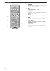
MODE Changes the brightness of the front panel display. (☞ P. 33) 6 En GETTING STARTED B POSITION Shifts the optimum listening area according to your listening position. (☞ P. 19) C TEST Outputs the test tone. (☞ P. 20) D ENHANCER Turns on and off compressed music enhancer mode alternately. (☞ P. 21) E NIGHT Turns night listening mode on or off. (☞ P. 32) F AREA Selects the optimum listening area. (☞ P. 20) G AUDIO DELAY Delays the output sound to synchronize it with the video image. (☞ P. 31) H DISP.
MODE Changes the brightness of the front panel display. (☞ P. 33) 6 En GETTING STARTED B POSITION Shifts the optimum listening area according to your listening position. (☞ P. 19) C TEST Outputs the test tone. (☞ P. 20) D ENHANCER Turns on and off compressed music enhancer mode alternately. (☞ P. 21) E NIGHT Turns night listening mode on or off. (☞ P. 32) F AREA Selects the optimum listening area. (☞ P. 20) G AUDIO DELAY Delays the output sound to synchronize it with the video image. (☞ P. 31) H DISP.
Owner's Manual
Page 11
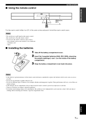
Notes • Be careful not to spill liquid on the inside of it toward the remote control sensor. extremely cold - dusty ■ Installing the batteries 1 Take off the battery compartment cover. 2 Insert the 2 supplied batteries (AAA, R03, UM4), observing the polarity markings (+ and -) on the remote control. • Be careful not to drop the remote control. • Do not leave the remote control in shape. • If the batteries run out, immediately remove them from the remote control to prevent an explosion or acid leak. • Dispose of batteries according to let leaking ...
Notes • Be careful not to spill liquid on the inside of it toward the remote control sensor. extremely cold - dusty ■ Installing the batteries 1 Take off the battery compartment cover. 2 Insert the 2 supplied batteries (AAA, R03, UM4), observing the polarity markings (+ and -) on the remote control. • Be careful not to drop the remote control. • Do not leave the remote control in shape. • If the batteries run out, immediately remove them from the remote control to prevent an explosion or acid leak. • Dispose of batteries according to let leaking ...
Owner's Manual
Page 12
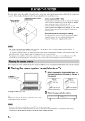
... TV, etc., by the subwoofer/system control may scratch or damage the surface of the spacers. Center system (YAS-71CU) Subwoofer/system control (YAS-71SPX) Center system (YAS-71CU) Place the center system beneath a TV or under the center system, use the supplied spacers as follows.... to a wall. Also produces virtual center channel sounds (dialogue, etc.) and virtual surround channel sounds effectively using the Yamaha front surround system. Subwoofer/system control (YAS-71SPX) Place the subwoofer near the center system and turn it slightly toward the center of the subwoofer. •...
... TV, etc., by the subwoofer/system control may scratch or damage the surface of the spacers. Center system (YAS-71CU) Subwoofer/system control (YAS-71SPX) Center system (YAS-71CU) Place the center system beneath a TV or under the center system, use the supplied spacers as follows.... to a wall. Also produces virtual center channel sounds (dialogue, etc.) and virtual surround channel sounds effectively using the Yamaha front surround system. Subwoofer/system control (YAS-71SPX) Place the subwoofer near the center system and turn it slightly toward the center of the subwoofer. •...
Owner's Manual
Page 13
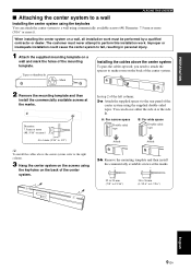
Tapes or thumbtacks Mark Installing the cables above the center system, refer to the right column. 3 Hang the center system on the screws using the supplied double-sided tapes. Diameter: 7.5 mm or more (#8, 5/16" or more )). Improper or inadequate installation could cause the center system to fall, resulting in personal injury. 1 Attach the supplied mounting template on a wall and mark the holes of the center system. 2 Remove the mounting template and then install the commercially available screws at the marks. 22 to 24 mm (7/8" to 15/16") 34 to 36 mm (1-5/16" to 1-7/16")...
Tapes or thumbtacks Mark Installing the cables above the center system, refer to the right column. 3 Hang the center system on the screws using the supplied double-sided tapes. Diameter: 7.5 mm or more (#8, 5/16" or more )). Improper or inadequate installation could cause the center system to fall, resulting in personal injury. 1 Attach the supplied mounting template on a wall and mark the holes of the center system. 2 Remove the mounting template and then install the commercially available screws at the marks. 22 to 24 mm (7/8" to 15/16") 34 to 36 mm (1-5/16" to 1-7/16")...
Owner's Manual
Page 14
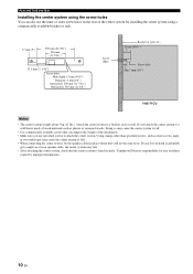
... of the center system for any accidents caused by improper installations. 10 En Using clamps other than specified screws, such as plaster or veneered woods. Yamaha will not become loose. PLACING THIS SYSTEM Installing the center system using the screw holes You can also use the inner or outer screw holes...: 6 mm (1/4") Inner pitch: 290 mm (11-7/16") Outer pitch: 550 mm (21-5/8") Screw (M6) Bracket or rack, etc., 15 mm (9/16") Screw hole Min 7 mm (1/4") YAS-71CU Notes • The center system weighs about 5 kg (11 lbs.). Attach the center system to a bracket, rack or wall.
... of the center system for any accidents caused by improper installations. 10 En Using clamps other than specified screws, such as plaster or veneered woods. Yamaha will not become loose. PLACING THIS SYSTEM Installing the center system using the screw holes You can also use the inner or outer screw holes...: 6 mm (1/4") Inner pitch: 290 mm (11-7/16") Outer pitch: 550 mm (21-5/8") Screw (M6) Bracket or rack, etc., 15 mm (9/16") Screw hole Min 7 mm (1/4") YAS-71CU Notes • The center system weighs about 5 kg (11 lbs.). Attach the center system to a bracket, rack or wall.
Owner's Manual
Page 15
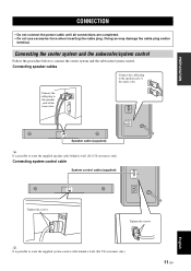
Connecting the center system and the subwoofer/system control Follow the procedure below to the speaker jack of the same color. Connect the cable plug to connect the center system and the subwoofer/system control. Tighten the screws. Connecting speaker cables Connect the cable plug to route the supplied speaker cable behind a wall. (For US customers only) 11 En English y It is possible to the speaker jack of the same color. Doing so may damage the cable plug and/or terminal. Speaker cable (supplied) y It is possible to route the supplied system control cable behind a wall....
Connecting the center system and the subwoofer/system control Follow the procedure below to the speaker jack of the same color. Connect the cable plug to connect the center system and the subwoofer/system control. Tighten the screws. Connecting speaker cables Connect the cable plug to route the supplied speaker cable behind a wall. (For US customers only) 11 En English y It is possible to the speaker jack of the same color. Doing so may damage the cable plug and/or terminal. Speaker cable (supplied) y It is possible to route the supplied system control cable behind a wall....
Owner's Manual
Page 16
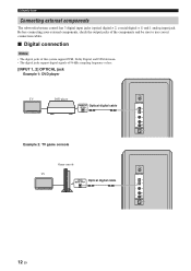
CONNECTION Connecting external components The subwoofer/system control has 3 digital input jacks (optical digital × 2, coaxial digital × 1) and 1 analog input jack. Before connecting your external components, check the output jacks of the components and be sure to use correct connection cables. ■ Digital connection Notes • The digital jacks of this system support PCM, Dolby Digital, and DTS bitstream. • The digital jacks support digital signals of 96 kHz sampling frequency or less. [INPUT 1, 2] OPTICAL jack Example 1: DVD player TV DVD player Optical digital ...
CONNECTION Connecting external components The subwoofer/system control has 3 digital input jacks (optical digital × 2, coaxial digital × 1) and 1 analog input jack. Before connecting your external components, check the output jacks of the components and be sure to use correct connection cables. ■ Digital connection Notes • The digital jacks of this system support PCM, Dolby Digital, and DTS bitstream. • The digital jacks support digital signals of 96 kHz sampling frequency or less. [INPUT 1, 2] OPTICAL jack Example 1: DVD player TV DVD player Optical digital ...
Owner's Manual
Page 18
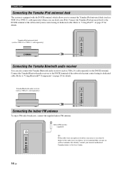
...universal dock (such as YDS-10 or YDS-11, sold separately) where you can also connect the Yamaha Bluetooth audio receiver (such as YBA-10, sold separately) to the DOCK terminal. CONNECTION Connecting the Yamaha iPod universal dock The system is weak in your area or you want to the DOCK terminal... of the subwoofer/system control using its dedicated cable. Yamaha Bluetooth audio receiver (such as YDS-10 or YDS-11, sold separately) Connecting the indoor FM antenna To enjoy FM radio broadcasts, connect the ...
...universal dock (such as YDS-10 or YDS-11, sold separately) where you can also connect the Yamaha Bluetooth audio receiver (such as YBA-10, sold separately) to the DOCK terminal. CONNECTION Connecting the Yamaha iPod universal dock The system is weak in your area or you want to the DOCK terminal... of the subwoofer/system control using its dedicated cable. Yamaha Bluetooth audio receiver (such as YDS-10 or YDS-11, sold separately) Connecting the indoor FM antenna To enjoy FM radio broadcasts, connect the ...
Owner's Manual
Page 19
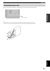
CONNECTION To AC wall outlet y You can attach the cover after you have made all connections or detach according to the rear panel of the subwoofer/system control. Attach the cover to your preference. PREPARATION English 15 En Connecting the power cable After you have made all connections, connect the power cable of the subwoofer/system control using the 6 supplied screws as shown.
CONNECTION To AC wall outlet y You can attach the cover after you have made all connections or detach according to the rear panel of the subwoofer/system control. Attach the cover to your preference. PREPARATION English 15 En Connecting the power cable After you have made all connections, connect the power cable of the subwoofer/system control using the 6 supplied screws as shown.
Owner's Manual
Page 20
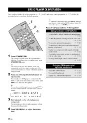
BASIC OPERATION BASIC PLAYBACK OPERATION Once you have finished all cable connections (☞ P. 11 to 15) and remote control preparation (☞ P. 7), follow the procedure below to standby mode, press STANDBY/ON again. This system is not activated ☞ P. 21 • To play back a Bluetooth component ☞ P. 22 ☞ P. 27 ☞ P. 29 3 Start playback on for the product. 4 Press VOLUME +/- quality sound ☞ P. 21 • To delay the sound output in order to synchronize it with surround mode ☞ P. 18 • To shift the optimum listening area from ...
BASIC OPERATION BASIC PLAYBACK OPERATION Once you have finished all cable connections (☞ P. 11 to 15) and remote control preparation (☞ P. 7), follow the procedure below to standby mode, press STANDBY/ON again. This system is not activated ☞ P. 21 • To play back a Bluetooth component ☞ P. 22 ☞ P. 27 ☞ P. 29 3 Start playback on for the product. 4 Press VOLUME +/- quality sound ☞ P. 21 • To delay the sound output in order to synchronize it with surround mode ☞ P. 18 • To shift the optimum listening area from ...
Owner's Manual
Page 21
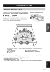
C: Center virtual speaker SR, SL: Surround virtual speakers FR, FL: Front speakers SBR, SBL: Surround back virtual speakers SW: Subwoofer You can check the virtual surround effect and adjust the volume balance according to enjoy a realistic 7.1 channel sound by simulating sound from virtual speakers at center, surround, and surround backs. AIR SURROUND XTREME What is AIR SURROUND XTREME ? See the following pages for enjoying 5.1 channel surround sound. ■ Virtual 7.1 channel The AIR SURROUND XTREME technology, using only the front left and right speakers of the subwoofer,...
C: Center virtual speaker SR, SL: Surround virtual speakers FR, FL: Front speakers SBR, SBL: Surround back virtual speakers SW: Subwoofer You can check the virtual surround effect and adjust the volume balance according to enjoy a realistic 7.1 channel sound by simulating sound from virtual speakers at center, surround, and surround backs. AIR SURROUND XTREME What is AIR SURROUND XTREME ? See the following pages for enjoying 5.1 channel surround sound. ■ Virtual 7.1 channel The AIR SURROUND XTREME technology, using only the front left and right speakers of the subwoofer,...