
English Manual
Page 2
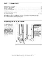
Remove the PART LIST/EXPLODED DRAWING before beginning assembly. until 7 p.m. WARNING DECAL PLACEMENT The decal shown at 1-800-736-6879, Monday through Saturday, 7 a.m. WEIDER is attached in the center of this product may result in the location shown. ! Central Time (excluding holidays), to the weight rack. Apply the replacement decal in ...
Remove the PART LIST/EXPLODED DRAWING before beginning assembly. until 7 p.m. WARNING DECAL PLACEMENT The decal shown at 1-800-736-6879, Monday through Saturday, 7 a.m. WEIDER is attached in the center of this product may result in the location shown. ! Central Time (excluding holidays), to the weight rack. Apply the replacement decal in ...
English Manual
Page 4
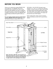
...they do not correspond to the rack; The WEIDER® PRO XT75 is 831.153220. High Pulley Station Chin-up Bar Right Side Lat Bar Left Side Weight Rest Weight Spotter Note: The terms "right side" and "left on a decal attached to help you achieve the specific results you ...develop every major muscle group of this manual carefully before calling. The serial number can be found on the drawings in muscle size and strength, or a healthier cardiovascular system, the WEIDER® PRO XT75 will help you want....
...they do not correspond to the rack; The WEIDER® PRO XT75 is 831.153220. High Pulley Station Chin-up Bar Right Side Lat Bar Left Side Weight Rest Weight Spotter Note: The terms "right side" and "left on a decal attached to help you achieve the specific results you ...develop every major muscle group of this manual carefully before calling. The serial number can be found on the drawings in muscle size and strength, or a healthier cardiovascular system, the WEIDER® PRO XT75 will help you want....
English Manual
Page 5
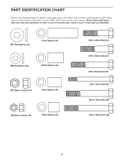
PART IDENTIFICATION CHART Refer to the drawings below to identify small parts used in the parts bag, check to see if it has been pre-attached. M10 Flat Washer (41) 51mm Spacer (43) M8 Flat Washer (40) 28mm Spacer (44) M10 Nylon Locknut (31) 24mm Spacer (42) M8 Nylon Locknut (32) ... is the key number of the part, from the PART LIST in the center of this manual. Note: Some small parts may have been pre-attached. The number in parentheses by each drawing is not in assembly.
PART IDENTIFICATION CHART Refer to the drawings below to identify small parts used in the parts bag, check to see if it has been pre-attached. M10 Flat Washer (41) 51mm Spacer (43) M8 Flat Washer (40) 28mm Spacer (44) M10 Nylon Locknut (31) 24mm Spacer (42) M8 Nylon Locknut (32) ... is the key number of the part, from the PART LIST in the center of this manual. Note: Some small parts may have been pre-attached. The number in parentheses by each drawing is not in assembly.
English Manual
Page 6
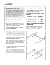
... be more convenient if you have a socket set, a set of open-end or closed-end wrenches, or a set of time, assembly will take time. Attach the Right and Left Bases (1, 3) to the Center Base (2) using two M10 x 78mm Bolts (33) and two M10 Nylon Locknuts (31). Most people find ... screwdriver • One Phillips screwdriver • Lubricant, such as grease or petroleum jelly, and soapy water. Do not dispose of the Weight Guide Base (4). 2 Attach the Foot Plate (5) and the Weight Guide Base (4) to realize that the versatile weight rack has many parts and that the weight rack can be...
... be more convenient if you have a socket set, a set of open-end or closed-end wrenches, or a set of time, assembly will take time. Attach the Right and Left Bases (1, 3) to the Center Base (2) using two M10 x 78mm Bolts (33) and two M10 Nylon Locknuts (31). Most people find ... screwdriver • One Phillips screwdriver • Lubricant, such as grease or petroleum jelly, and soapy water. Do not dispose of the Weight Guide Base (4). 2 Attach the Foot Plate (5) and the Weight Guide Base (4) to realize that the versatile weight rack has many parts and that the weight rack can be...
English Manual
Page 7
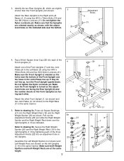
... 5a. Press six Square Bushings (21) into an adjustment hole in the same manner. Make sure that the Uprights are facing each other. 1 33 Attach the other Front Upright (7, not shown) and two Joint Plates (6, not shown) to the right Uprights (7, 8) by tightening each of the Front Uprights... (7). 4 Attach one of the Front Upright and the holes in the same manner. 5. Pull out the 5a Adjustment Knobs (22) and slide the Right Weight Spotter ...
... 5a. Press six Square Bushings (21) into an adjustment hole in the same manner. Make sure that the Uprights are facing each other. 1 33 Attach the other Front Upright (7, not shown) and two Joint Plates (6, not shown) to the right Uprights (7, 8) by tightening each of the Front Uprights... (7). 4 Attach one of the Front Upright and the holes in the same manner. 5. Pull out the 5a Adjustment Knobs (22) and slide the Right Weight Spotter ...
English Manual
Page 8
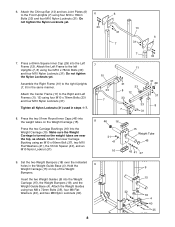
...12). Make sure the Weight Carriage is turned so the weight tubes are near the top, as shown. Attach the Weight Guides using an M10 x 66mm Bolt (37), two M10 Flat Washers (41), the 51mm...33 33 7 31 31 29 31 8 8 46 16 31 41 16 15 Weight Tube 46 43 41 37 9. Attach the Center Frame (11) to the right Uprights (7, 8) in the same manner. Tighten all Nylon Locknuts (31) used... not tighten the Nylon Locknuts yet. Do not tighten the Nylon Locknuts yet. 33 13 31 6 7 31 7. 6. Attach the Chin-up Bar (13) and two Joint Plates (6) to the left Uprights (7, 8) using four M10 x 78mm ...
...12). Make sure the Weight Carriage is turned so the weight tubes are near the top, as shown. Attach the Weight Guides using an M10 x 66mm Bolt (37), two M10 Flat Washers (41), the 51mm...33 33 7 31 31 29 31 8 8 46 16 31 41 16 15 Weight Tube 46 43 41 37 9. Attach the Center Frame (11) to the right Uprights (7, 8) in the same manner. Tighten all Nylon Locknuts (31) used... not tighten the Nylon Locknuts yet. Do not tighten the Nylon Locknuts yet. 33 13 31 6 7 31 7. 6. Attach the Chin-up Bar (13) and two Joint Plates (6) to the left Uprights (7, 8) using four M10 x 78mm ...

English Manual
Page 9
...on the other end. Route the metal-sleeve end of the Center Frame (11) and the Weight Guides (9). Attach the Weight Guides to the Center Frame (11) using two M10 x 50mm Bolts (47) and two M10 Nylon...end of the High Cable and a metal sleeve on one end of the Weight Guide Frame (14). Attach two Pulleys (25) inside the bracket on the Weight Guide Frame (14), down through the indicated hole...longer of the Weight Carriage (15). Lift the High Cable (26) in the center of the two Cables. Attach the Weight Guide Frame (14) to the Weight Guide Frame using an M10 x 66mm Bolt (37), two...
...on the other end. Route the metal-sleeve end of the Center Frame (11) and the Weight Guides (9). Attach the Weight Guides to the Center Frame (11) using two M10 x 50mm Bolts (47) and two M10 Nylon...end of the High Cable and a metal sleeve on one end of the Weight Guide Frame (14). Attach two Pulleys (25) inside the bracket on the Weight Guide Frame (14), down through the indicated hole...longer of the Weight Carriage (15). Lift the High Cable (26) in the center of the two Cables. Attach the Weight Guide Frame (14) to the Weight Guide Frame using an M10 x 66mm Bolt (37), two...
English Manual
Page 10
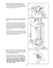
...(25) in the Pulley Plates. In addition, make sure the Cables are inserted through the bracket on one end. Attach the Low Cable using an M10 x 45mm Bolt (34) and an M10 Nylon Locknut (31). Lay the Low ...Cable (27) over a Pulley (25) as shown. 16 Attach a Cable Trap (24) and the two Pulley Plates (17) to the Pulley Plates (17) using an M10 x ...an M10 x 45mm Bolt (34) and an M10 Nylon Locknut (31). 26 27 25 41 44 2 31 16. Attach two Pulleys (25) inside the bracket using an M10 x 45mm Bolt (34) and an M10 Nylon Locknut (31)....
...(25) in the Pulley Plates. In addition, make sure the Cables are inserted through the bracket on one end. Attach the Low Cable using an M10 x 45mm Bolt (34) and an M10 Nylon Locknut (31). Lay the Low ...Cable (27) over a Pulley (25) as shown. 16 Attach a Cable Trap (24) and the two Pulley Plates (17) to the Pulley Plates (17) using an M10 x ...an M10 x 45mm Bolt (34) and an M10 Nylon Locknut (31). 26 27 25 41 44 2 31 16. Attach two Pulleys (25) inside the bracket using an M10 x 45mm Bolt (34) and an M10 Nylon Locknut (31)....
English Manual
Page 13
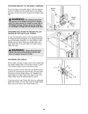
... below. Weight Tube Weight Tube 15 50 26 23 38 17 31 25 24 17 34 24 13 ATTACHING THE LAT BAR TO THE HIGH PULLEY STATION OR THE LOW PULLEY STATION To use the high or low...of holes in the Pulley Plates (17). Remove the M10 x 45mm Bolt (34) and the M10 Nylon Locknut (31) attaching the lower Pulley (25) and Cable Trap (24) to the High Cable (26) or the Low Cable (not shown)...tighten the cables, you can stretch slightly after it is slack in the Pulley Plates using the Lat Bar. ATTACHING WEIGHTS TO THE WEIGHT CARRIAGE To use the high pulley station or the low pulley station, first place the...
... below. Weight Tube Weight Tube 15 50 26 23 38 17 31 25 24 17 34 24 13 ATTACHING THE LAT BAR TO THE HIGH PULLEY STATION OR THE LOW PULLEY STATION To use the high or low...of holes in the Pulley Plates (17). Remove the M10 x 45mm Bolt (34) and the M10 Nylon Locknut (31) attaching the lower Pulley (25) and Cable Trap (24) to the High Cable (26) or the Low Cable (not shown)...tighten the cables, you can stretch slightly after it is slack in the Pulley Plates using the Lat Bar. ATTACHING WEIGHTS TO THE WEIGHT CARRIAGE To use the high pulley station or the low pulley station, first place the...
English Manual
Page 18
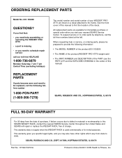
...., HOFFMAN ESTATES, IL 60179 FULL 90-DAY WARRANTY For 90 days from state to find that: • you visit your WEIDER® PRO XT75 are listed on a decal attached to order parts by telephone, call the following information: • The MODEL NUMBER of the product (831.153220) •... The NAME of the product (WEIDER® PRO XT75 weight rack) • The PART NUMBER and DESCRIPTION of your nearest SEARS Service Center....
...., HOFFMAN ESTATES, IL 60179 FULL 90-DAY WARRANTY For 90 days from state to find that: • you visit your WEIDER® PRO XT75 are listed on a decal attached to order parts by telephone, call the following information: • The MODEL NUMBER of the product (831.153220) •... The NAME of the product (WEIDER® PRO XT75 weight rack) • The PART NUMBER and DESCRIPTION of your nearest SEARS Service Center....

