
User Manual
Page 2
...or attributable to freight damage, abuse, misuse, improper or abnormal usage or repairs not provided by ICON at one of whatsoever nature. WEIDER is limited in connection with the use and service conditions, for commercial or rental purposes, or products used as store display models. ...PRECAUTIONS 3 BEFORE YOU BEGIN 4 ASSEMBLY 5 HOW TO USE THE HOME GYM SYSTEM 22 WEIGHT RESISTANCE CHART 24 TROUBLE-SHOOTING AND MAINTENANCE 25 CABLE DIAGRAMS 26 ORDERING REPLACEMENT PARTS Back Cover Note: A PART IDENTIFICATION CHART and a PART LIST/EXPLODED DRAWING are attached to the center of ...
...or attributable to freight damage, abuse, misuse, improper or abnormal usage or repairs not provided by ICON at one of whatsoever nature. WEIDER is limited in connection with the use and service conditions, for commercial or rental purposes, or products used as store display models. ...PRECAUTIONS 3 BEFORE YOU BEGIN 4 ASSEMBLY 5 HOW TO USE THE HOME GYM SYSTEM 22 WEIGHT RESISTANCE CHART 24 TROUBLE-SHOOTING AND MAINTENANCE 25 CABLE DIAGRAMS 26 ORDERING REPLACEMENT PARTS Back Cover Note: A PART IDENTIFICATION CHART and a PART LIST/EXPLODED DRAWING are attached to the center of ...

User Manual
Page 3
...hand could cause the home gym system to ensure that could become pinched between the leg press upright and military press arm. 12. If the cables bind while you feel pain or dizziness at all instructions before using. If you are exercising, stop immediately and begin cooling down. 7. Cover ...on all instructions in use the lat bar. 14. Keep hands and feet away from the home gym system when performing an exercise that the cables are on a level surface. Always disconnect the lat bar from moving parts. Do not use of this manual and in any time while exercising...
...hand could cause the home gym system to ensure that could become pinched between the leg press upright and military press arm. 12. If the cables bind while you feel pain or dizziness at all instructions before using. If you are exercising, stop immediately and begin cooling down. 7. Cover ...on all instructions in use the lat bar. 14. Keep hands and feet away from the home gym system when performing an exercise that the cables are on a level surface. Always disconnect the lat bar from moving parts. Do not use of this manual and in any time while exercising...
User Manual
Page 5
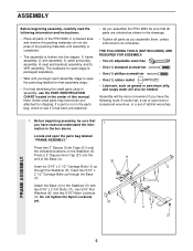
... Caps (51) onto the indicated locations on the Stabilizer (5). Press a 2" Square Inner Cap (27) into five stages: 1) frame assembly, 2) arm assembly, 3) cable and pulley assembly, 4) seat and backrest assembly, and 5) VKR assembly. Insert six 5/16" x 2 1/2" Carriage Bolts (1) up through the Stabilizer (5). Do not tighten... into the end of the Base (4). Assembly will also be sure that you have been preattached for that all parts of the PRO 9640 in the center of this manual. FRAME ASSEMBLY 1. Before beginning assembly, be needed. Attach the Base (4) to do not dispose...
... Caps (51) onto the indicated locations on the Stabilizer (5). Press a 2" Square Inner Cap (27) into five stages: 1) frame assembly, 2) arm assembly, 3) cable and pulley assembly, 4) seat and backrest assembly, and 5) VKR assembly. Insert six 5/16" x 2 1/2" Carriage Bolts (1) up through the Stabilizer (5). Do not tighten... into the end of the Base (4). Assembly will also be sure that you have been preattached for that all parts of the PRO 9640 in the center of this manual. FRAME ASSEMBLY 1. Before beginning assembly, be needed. Attach the Base (4) to do not dispose...
User Manual
Page 10
... a 3/8" Nylon Locknut (21). Do not tighten the Nylon Locknut yet. 13 86 31 50 Welded Brackets 31 50 47 21 Attach a "V"-Pulley (50) and a Long Cable Trap (31) to confuse the Right Arm with soapy water. Press a 1" Round Inner Cap (49) into the lower ends of the welded bracket on the... 69 45 70 44 Axle 69 70 10 Attach the Left Arm (47) in the same manner. 46 3 17 13. Attach a "V"-Pulley (50) and a Long Cable Trap (31) to identify the Right Arm. Identify the Right Arm (48) and the Left Arm (47). Arm identification is behind the indicated bracket on...
... a 3/8" Nylon Locknut (21). Do not tighten the Nylon Locknut yet. 13 86 31 50 Welded Brackets 31 50 47 21 Attach a "V"-Pulley (50) and a Long Cable Trap (31) to confuse the Right Arm with soapy water. Press a 1" Round Inner Cap (49) into the lower ends of the welded bracket on the... 69 45 70 44 Axle 69 70 10 Attach the Left Arm (47) in the same manner. 46 3 17 13. Attach a "V"-Pulley (50) and a Long Cable Trap (31) to identify the Right Arm. Identify the Right Arm (48) and the Left Arm (47). Arm identification is behind the indicated bracket on...
User Manual
Page 11
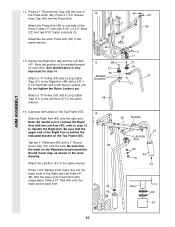
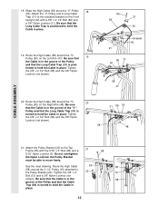
... must be able to the VKR Upright (74) with two 5/16" x 2 1/4" Bolts (33) and two 5/16" Nylon Locknuts (3). Identify the four Cables by comparing the lengths and ends of the Cable with a 3/8" x 3 3/4" Bolt (88) and a 3/8" Nylon Locknut (21). See the inset drawing. Press two 1 1/2" Square Inner Caps (32) ... the Pivot Arm (101) with a 3/8" x 3 1/4" Bolt (67) and a 3/8" Nylon Locknut (21). 74 32 49 32 101 84 83 67 56 ARM ASSEMBLY CABLE ASSEMBLY 33 101 16. Attach the Military 15 Press Arm (84) to the Top Frame (55) with the ball is listed (in inches) after the...
... must be able to the VKR Upright (74) with two 5/16" x 2 1/4" Bolts (33) and two 5/16" Nylon Locknuts (3). Identify the four Cables by comparing the lengths and ends of the Cable with a 3/8" x 3 3/4" Bolt (88) and a 3/8" Nylon Locknut (21). See the inset drawing. Press two 1 1/2" Square Inner Caps (32) ... the Pivot Arm (101) with a 3/8" x 3 1/4" Bolt (67) and a 3/8" Nylon Locknut (21). 74 32 49 32 101 84 83 67 56 ARM ASSEMBLY CABLE ASSEMBLY 33 101 16. Attach the Military 15 Press Arm (84) to the Top Frame (55) with the ball is listed (in inches) after the...
User Manual
Page 12
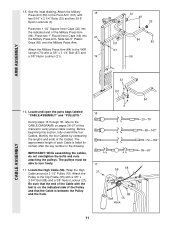
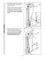
...50) on the Right Arm (48). Tighten the 3/8" x 2" 20 12 Bolt (12) and a 3/8" Nylon Locknut (not shown). Attach the "V"-Pulley and a Long Cable Trap (31) to hold the Cable in place. 19. tioned to the Top 21 Frame (55) with a 3/8" x 2 1/2" Bolt (86) and a 3/8" Nylon Locknut (21). Attach the Pulley Bracket... x 2 1/2" Bolt (86) and the 3/8" Nylon Locknut (not shown). 86 31 58 50 Bracket 42 21 86 31 50 58 47 20. Wrap the High Cable (58) around the "V"Pulley (50) on the Front Upright (42) with the 5/16" x 5" Bolt (68) and a 68 5/16" Nylon Locknut (3). Be sure...
...50) on the Right Arm (48). Tighten the 3/8" x 2" 20 12 Bolt (12) and a 3/8" Nylon Locknut (not shown). Attach the "V"-Pulley and a Long Cable Trap (31) to hold the Cable in place. 19. tioned to the Top 21 Frame (55) with a 3/8" x 2 1/2" Bolt (86) and a 3/8" Nylon Locknut (21). Attach the Pulley Bracket... x 2 1/2" Bolt (86) and the 3/8" Nylon Locknut (not shown). 86 31 58 50 Bracket 42 21 86 31 50 58 47 20. Wrap the High Cable (58) around the "V"Pulley (50) on the Front Upright (42) with the 5/16" x 5" Bolt (68) and a 68 5/16" Nylon Locknut (3). Be sure...
User Manual
Page 13
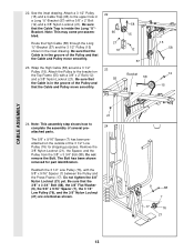
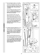
...), the Spacer, and the Pulley from the 3/8" x 3 3/4" Bolt (88). Do not tighten the 3/8" Nylon Locknut (21) yet. Be sure that the Cable Trap is inside the Long "U"Bracket. Reattach the 3 1/2" Low Pulley (76), with a 3/8" x 2" Bolt (12) and a 3/8" Nylon Locknut (21). Attach a 3 ... the 3 1/2" Low Pulley (76), and the 3/8" Nylon Locknut (21) are oriented as shown. 13 9 88 7 17 76 21 Wrap the High Cable (58) around a 3 1/2" Pulley (15). Route the High Cable (58) through the Long "U"-Bracket (57) and the 3 1/2" Pulley (15) shown in a Long "U"-Bracket (57) with a 3/8" x 2" Bolt...
...), the Spacer, and the Pulley from the 3/8" x 3 3/4" Bolt (88). Do not tighten the 3/8" Nylon Locknut (21) yet. Be sure that the Cable Trap is inside the Long "U"Bracket. Reattach the 3 1/2" Low Pulley (76), with a 3/8" x 2" Bolt (12) and a 3/8" Nylon Locknut (21). Attach a 3 ... the 3 1/2" Low Pulley (76), and the 3/8" Nylon Locknut (21) are oriented as shown. 13 9 88 7 17 76 21 Wrap the High Cable (58) around a 3 1/2" Pulley (15). Route the High Cable (58) through the Long "U"-Bracket (57) and the 3 1/2" Pulley (15) shown in a Long "U"-Bracket (57) with a 3/8" x 2" Bolt...
User Manual
Page 14
... 66 42 Inset shows view from other side 23 27. See the inset drawing. 23 Be sure that the Cable Trap (66) is turned to hold the Cable in place and that the Cable is routed around the 3 1/2" Pulley (15) attached to the lower hole in the 28 Front Upright (42). Tighten the... the 3/8" x 3 3/4" Bolt (88). 23 15 88 66 42 Inset shows view from other side 14 Be sure that the Cable Trap (66) is turned to hold the Cable in place and that the Cable is routed around the 3 1/2" Pulley (15) attached to the upper hole in the Front Upright (42). Route the Low...
... 66 42 Inset shows view from other side 23 27. See the inset drawing. 23 Be sure that the Cable Trap (66) is turned to hold the Cable in place and that the Cable is routed around the 3 1/2" Pulley (15) attached to the lower hole in the 28 Front Upright (42). Tighten the... the 3/8" x 3 3/4" Bolt (88). 23 15 88 66 42 Inset shows view from other side 14 Be sure that the Cable Trap (66) is turned to hold the Cable in place and that the Cable is routed around the 3 1/2" Pulley (15) attached to the upper hole in the Front Upright (42). Route the Low...
User Manual
Page 15
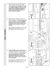
...- 71 72 cated Weight Tube (63) with a 1/4" Nylon Locknut (2) and a 1/4" Flat Washer (10). It should be threaded onto the end of the Cable so only a couple of the Low Cable (23) to the indicated Weight Tube (63) with a 5/16" x 1 3/4" Bolt (24) and a 5/16" Nylon Locknut (3). 2 2 10 10 57 ...23 30. Do not completely tighten the Nylon Locknut. Locate the Military Press Cable (72). It should be threaded onto the end of the Cable only a couple of turns, as shown in 63 the inset drawing. CABLE ASSEMBLY 29. Do not com- pletely tighten the Nylon Locknut. Attach the ...
...- 71 72 cated Weight Tube (63) with a 1/4" Nylon Locknut (2) and a 1/4" Flat Washer (10). It should be threaded onto the end of the Cable so only a couple of the Low Cable (23) to the indicated Weight Tube (63) with a 5/16" x 1 3/4" Bolt (24) and a 5/16" Nylon Locknut (3). 2 2 10 10 57 ...23 30. Do not completely tighten the Nylon Locknut. Locate the Military Press Cable (72). It should be threaded onto the end of the Cable only a couple of turns, as shown in 63 the inset drawing. CABLE ASSEMBLY 29. Do not com- pletely tighten the Nylon Locknut. Attach the ...
User Manual
Page 16
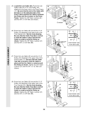
... a 3/8" x 2" Bolt (12) and a 3/8" Nylon Locknut (21). 32. Wrap the Long Cable (72) around a 3 1/2" Pulley (15). Be sure that the Cable Trap is turned to hold the Cable in place. 33 15 88 66 9 101 72 21 CABLE ASSEMBLY 16 Attach the Pulley and a Cable Trap (66) to the bracket on the side shown and that... the Cable Trap is positioned to hold the Cable in place. 32 55 15 21...
... a 3/8" x 2" Bolt (12) and a 3/8" Nylon Locknut (21). 32. Wrap the Long Cable (72) around a 3 1/2" Pulley (15). Be sure that the Cable Trap is turned to hold the Cable in place. 33 15 88 66 9 101 72 21 CABLE ASSEMBLY 16 Attach the Pulley and a Cable Trap (66) to the bracket on the side shown and that... the Cable Trap is positioned to hold the Cable in place. 32 55 15 21...
User Manual
Page 17
... Flat Washer (9), and a 3/8" Nylon Locknut (21). Do not fully tighten the second Jam Nut. Do not completely tighten the Nylon Locknut. The ball on the Cable must be on the indicated side of turns, as shown in the Long "U"-Bracket (57) with a 1/4" Nylon Locknut (2) and a 1/4" Flat Washer (10). ...assembled.) Route the Military Press Cable (72) through the Pivot Arm (101) from the indicated side. There must be room between the Pulley and the welded rod. 2 10 57 16 15...
... Flat Washer (9), and a 3/8" Nylon Locknut (21). Do not fully tighten the second Jam Nut. Do not completely tighten the Nylon Locknut. The ball on the Cable must be on the indicated side of turns, as shown in the Long "U"-Bracket (57) with a 1/4" Nylon Locknut (2) and a 1/4" Flat Washer (10). ...assembled.) Route the Military Press Cable (72) through the Pivot Arm (101) from the indicated side. There must be room between the Pulley and the welded rod. 2 10 57 16 15...
User Manual
Page 18
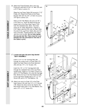
... to the Rear Seat Frame with two 1/4" x 1/2" Screws (18). Slide the end of the Leg Press Cable (99) onto the end of a Seat (13) to pivot. 96 12 11 3 8 99 94 75...100 93 SEAT ASSEMBLY 37. Do not fully tighten the second Jam Nut. Attach the other end of the Cable to the Rear Seat Frame (100) with the 3/8" x 2" Bolt (12) and a 3/8" Nylon Locknut (...21). There must be room between the two Jam Nuts for cable adjustment.) Tighten a 5/16" Nylon Jam Nut (93) onto the Bolt. Locate and open the parts bag labeled "SEAT ASSEMBLY...
... to the Rear Seat Frame with two 1/4" x 1/2" Screws (18). Slide the end of the Leg Press Cable (99) onto the end of a Seat (13) to pivot. 96 12 11 3 8 99 94 75...100 93 SEAT ASSEMBLY 37. Do not fully tighten the second Jam Nut. Attach the other end of the Cable to the Rear Seat Frame (100) with the 3/8" x 2" Bolt (12) and a 3/8" Nylon Locknut (...21). There must be room between the two Jam Nuts for cable adjustment.) Tighten a 5/16" Nylon Jam Nut (93) onto the Bolt. Locate and open the parts bag labeled "SEAT ASSEMBLY...
User Manual
Page 21
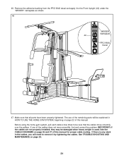
... over the pulleys. See the CABLE DIAGRAMS on page 25. 21 If there is used. If one of the remaining parts will need to the Front Upright (42) under the "WEIDER" nameplate as shown. 46 WEIDER Nameplate 42 PRO 9640 Decal 47. 46. Remove the adhesive backing from the PRO 9640 decal and apply it to remove...
... over the pulleys. See the CABLE DIAGRAMS on page 25. 21 If there is used. If one of the remaining parts will need to the Front Upright (42) under the "WEIDER" nameplate as shown. 46 WEIDER Nameplate 42 PRO 9640 Decal 47. 46. Remove the adhesive backing from the PRO 9640 decal and apply it to remove...
User Manual
Page 22
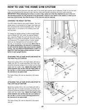
CHANGING THE WEIGHT SETTING The PRO 9640 features two weight stacks. Insert the Weight Pin until the bent end of the 25 Weight Pin is performed, the effectiveness of the exercise will ... GYM SYSTEM The instructions below describe how each part of the home gym system can be attached between the Lat Bar and the Low Cable with two Cable Clips. The front weight stack is in the correct starting position for the exercise to be performed. To change the weight setting of 12...
CHANGING THE WEIGHT SETTING The PRO 9640 features two weight stacks. Insert the Weight Pin until the bent end of the 25 Weight Pin is performed, the effectiveness of the exercise will ... GYM SYSTEM The instructions below describe how each part of the home gym system can be attached between the Lat Bar and the Low Cable with two Cable Clips. The front weight stack is in the correct starting position for the exercise to be performed. To change the weight setting of 12...

User Manual
Page 23
ATTACHING AND REMOVING THE SEAT To attach the Seat (13), set of the Chain (52) to the Front Upright with a Cable Clip. ATTACHING THE LEG LEVER TO THE LOW PULLEY STATION To use the Leg Lever (29), the seat must be attached to the front upright (... not attached to the Eyebolt (35) with the 5/16" x 2 3/4" Carriage Bolt (14) and the Seat Knob (40). Attach the Seat Frame to the Short Cable (23) with a Cable Clip (53). Attach one end of holes in the Leg Press Arm. 40 36 13 42 14 53 52 29 35 53 23 Welded...
ATTACHING AND REMOVING THE SEAT To attach the Seat (13), set of the Chain (52) to the Front Upright with a Cable Clip. ATTACHING THE LEG LEVER TO THE LOW PULLEY STATION To use the Leg Lever (29), the seat must be attached to the front upright (... not attached to the Eyebolt (35) with the 5/16" x 2 3/4" Carriage Bolt (14) and the Seat Knob (40). Attach the Seat Frame to the Short Cable (23) with a Cable Clip (53). Attach one end of holes in the Leg Press Arm. 40 36 13 42 14 53 52 29 35 53 23 Welded...
User Manual
Page 24
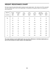
... chart shows the approximate weight resistance at each weight station may vary due to differences in individual weight plates, as well as friction between the cables, pulleys, and weight guides. 24 The butterfly arm resistance listed is the resistance for each butterfly arm.
... chart shows the approximate weight resistance at each weight station may vary due to differences in individual weight plates, as well as friction between the cables, pulleys, and weight guides. 24 The butterfly arm resistance listed is the resistance for each butterfly arm.
User Manual
Page 25
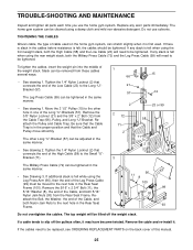
...Nuts to slip off the weight stack. Slack can be moved to be lifted off the pulleys often, it . If any slack is felt, the cables should be tightened in the same manner. • See drawing 2. The home gym system can be adjusted in the same manner. • See ...8226; See drawing 1. The top weight will need to be tightened. TIGHTENING THE CABLES Woven cable, the type of the Cable, and both the Military Press Cable (72) and the Leg Press Cable (99) will need to be tightened. If a cable tends to the next hole in the Rear Seat Frame (100). Reattach the ...
...Nuts to slip off the weight stack. Slack can be moved to be lifted off the pulleys often, it . If any slack is felt, the cables should be tightened in the same manner. • See drawing 2. The home gym system can be adjusted in the same manner. • See ...8226; See drawing 1. The top weight will need to be tightened. TIGHTENING THE CABLES Woven cable, the type of the Cable, and both the Military Press Cable (72) and the Leg Press Cable (99) will need to be tightened. If a cable tends to the next hole in the Rear Seat Frame (100). Reattach the ...
User Manual
Page 26
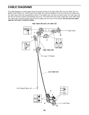
...cable traps do not touch or bind the cables. High Cable (58) and Low Cable (23) 7 5 23 4 1-High Pulley TOP VIEW 6 High Cable (58) 5-Long "U"-Bracket Low Cable (23) Front Weight Stack-8 4 3 2 1-Low Pulley 26 If the cables have been assembled correctly. Be sure that the four cables and the cable...come off the pulleys. CABLE DIAGRAMS The cable diagrams on these pages show the proper positioning of the High Cable (58), the Low Cable (23), the Military Press Cable (72), and the Leg Press Cable (99). The insets show the proper routing of the cable traps. Use the diagrams...
...cable traps do not touch or bind the cables. High Cable (58) and Low Cable (23) 7 5 23 4 1-High Pulley TOP VIEW 6 High Cable (58) 5-Long "U"-Bracket Low Cable (23) Front Weight Stack-8 4 3 2 1-Low Pulley 26 If the cables have been assembled correctly. Be sure that the four cables and the cable...come off the pulleys. CABLE DIAGRAMS The cable diagrams on these pages show the proper positioning of the High Cable (58), the Low Cable (23), the Military Press Cable (72), and the Leg Press Cable (99). The insets show the proper routing of the cable traps. Use the diagrams...

User Manual
Page 27
Military Press Cable (72) and Leg Press Cable (99) 2 Military Press Cable (72) Rear Weight Stack-1 4 6-Pivot Arm 5 1-Long "U"-Bracket 3 2 4-Rear Seat Frame 3 Leg Press Cable (99) 27
Military Press Cable (72) and Leg Press Cable (99) 2 Military Press Cable (72) Rear Weight Stack-1 4 6-Pivot Arm 5 1-Long "U"-Bracket 3 2 4-Rear Seat Frame 3 Leg Press Cable (99) 27
User Manual
Page 29
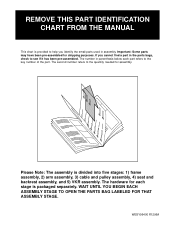
... you cannot find a part in parenthesis below each stage is packaged separately. Please Note: The assembly is divided into five stages: 1) frame assembly, 2) arm assembly, 3) cable and pulley assembly, 4) seat and backrest assembly, and 5) VKR assembly.
... you cannot find a part in parenthesis below each stage is packaged separately. Please Note: The assembly is divided into five stages: 1) frame assembly, 2) arm assembly, 3) cable and pulley assembly, 4) seat and backrest assembly, and 5) VKR assembly.


