
User Manual
Page 1
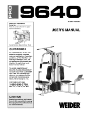
... parts, we will provide immediate assistance, free of charge to providing complete customer satisfaction. Write the serial number in this manual before using this manual for reference. If you complete satisfaction through direct assistance from our factory. The trained ... p.m. Serial Number Decal (Under Seat) QUESTIONS? PATENT PENDING USER'S MANUAL Model No. WESY96400 Serial No. Save this equipment. MST CAUTION Read all precautions and instructions in the space above for future reference. TO AVOID UNNECESSARY DELAYS, PLEASE CALL DIRECT TO OUR TOLL-FREE CUSTOMER ...
... parts, we will provide immediate assistance, free of charge to providing complete customer satisfaction. Write the serial number in this manual before using this manual for reference. If you complete satisfaction through direct assistance from our factory. The trained ... p.m. Serial Number Decal (Under Seat) QUESTIONS? PATENT PENDING USER'S MANUAL Model No. WESY96400 Serial No. Save this equipment. MST CAUTION Read all precautions and instructions in the space above for future reference. TO AVOID UNNECESSARY DELAYS, PLEASE CALL DIRECT TO OUR TOLL-FREE CUSTOMER ...
User Manual
Page 2
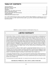
... of removal, installation or other consequential damages of merchantability or fitness for a period of ninety (90) days from state to the original purchaser. ICON HEALTH & FITNESS, INC., 1500 S. 1000 W., LOGAN, UT 84321-9813 2 TABLE OF CONTENTS LIMITED WARRANTY 2 IMPORTANT PRECAUTIONS 3 BEFORE YOU BEGIN 4 ASSEMBLY 5 HOW TO USE THE HOME GYM SYSTEM 22 WEIGHT RESISTANCE CHART 24 TROUBLE-SHOOTING AND MAINTENANCE 25 CABLE DIAGRAMS 26 ORDERING REPLACEMENT PARTS Back Cover Note: A PART IDENTIFICATION CHART and a PART LIST...
... of removal, installation or other consequential damages of merchantability or fitness for a period of ninety (90) days from state to the original purchaser. ICON HEALTH & FITNESS, INC., 1500 S. 1000 W., LOGAN, UT 84321-9813 2 TABLE OF CONTENTS LIMITED WARRANTY 2 IMPORTANT PRECAUTIONS 3 BEFORE YOU BEGIN 4 ASSEMBLY 5 HOW TO USE THE HOME GYM SYSTEM 22 WEIGHT RESISTANCE CHART 24 TROUBLE-SHOOTING AND MAINTENANCE 25 CABLE DIAGRAMS 26 ORDERING REPLACEMENT PARTS Back Cover Note: A PART IDENTIFICATION CHART and a PART LIST...

User Manual
Page 3
... institutional setting. 9. Always stand on the pulleys at all precautions. 10. Never release the press arm, butterfly arms, military press arm, leg lever, leg press plate, lat bar or nylon strap while weights are adequately informed of all times. If you are exercising, stop immediately and begin cooling down. 7. Do not use . 8. The home gym system is especially important for home use the lat bar. 14. Replace any exercise program, consult your hands away from the home gym system...
... institutional setting. 9. Always stand on the pulleys at all precautions. 10. Never release the press arm, butterfly arms, military press arm, leg lever, leg press plate, lat bar or nylon strap while weights are adequately informed of all times. If you are exercising, stop immediately and begin cooling down. 7. Do not use . 8. The home gym system is especially important for home use the lat bar. 14. Replace any exercise program, consult your hands away from the home gym system...
User Manual
Page 4
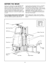
... model number and serial number before using the WEIDER® PRO 9640 Home Gym System. Width: 89 in . For your cardiovascular system, the PRO 9640 will help us assist you want. Customer Service Department toll-free at 1-800-9993756, Monday through Friday, 6 a.m. If you for selecting the versatile WEIDER® PRO 9640 Home Gym System. The PRO 9640 offers a selection of the body. until 6 p.m. Mountain Time (excluding holidays). Lat Bar High Pulley Station VKR Arms Butterfly Arms ASSEMBLED DIMENSIONS...
... model number and serial number before using the WEIDER® PRO 9640 Home Gym System. Width: 89 in . For your cardiovascular system, the PRO 9640 will help us assist you want. Customer Service Department toll-free at 1-800-9993756, Monday through Friday, 6 a.m. If you for selecting the versatile WEIDER® PRO 9640 Home Gym System. The PRO 9640 offers a selection of the body. until 6 p.m. Mountain Time (excluding holidays). Lat Bar High Pulley Station VKR Arms Butterfly Arms ASSEMBLED DIMENSIONS...
User Manual
Page 5
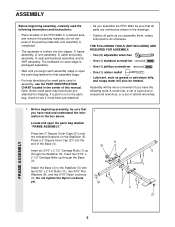
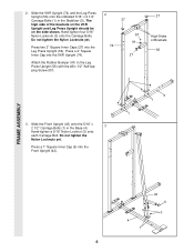
... the small parts used in assembly, use the PART IDENTIFICATION CHART located in the drawings. • Tighten all parts as grease or petroleum jelly, and soapy water will be needed. Locate and open the parts bag labeled for that all parts of the PRO 9640 in the box above. Press a 2" Square Inner Cap (27) into five stages: 1) frame assembly, 2) arm assembly, 3) cable and pulley assembly, 4) seat and backrest assembly, and 5) VKR assembly. Insert two 5/16" x 2 1/2" Carriage Bolts up...
... the small parts used in assembly, use the PART IDENTIFICATION CHART located in the drawings. • Tighten all parts as grease or petroleum jelly, and soapy water will be needed. Locate and open the parts bag labeled for that all parts of the PRO 9640 in the box above. Press a 2" Square Inner Cap (27) into five stages: 1) frame assembly, 2) arm assembly, 3) cable and pulley assembly, 4) seat and backrest assembly, and 5) VKR assembly. Insert two 5/16" x 2 1/2" Carriage Bolts up...
User Manual
Page 6
... Nylon Locknuts yet. Slide the VKR Upright (74) and the Leg Press Upright (56) onto the indicated 5/16" x 2 1/2" Carriage Bolts (1) in the Base (4). 3 Hand-tighten a 5/16" Nylon Locknut (3) onto each Carriage Bolt. Press two 2" Square Inner Caps (27) into the VKR Upright (74). Attach the Rubber Bumper (91) to the Leg Press Upright (56) with the #8 x 1/2" Self-tapping Screw (87). 2 27 87 91 74...
... Nylon Locknuts yet. Slide the VKR Upright (74) and the Leg Press Upright (56) onto the indicated 5/16" x 2 1/2" Carriage Bolts (1) in the Base (4). 3 Hand-tighten a 5/16" Nylon Locknut (3) onto each Carriage Bolt. Press two 2" Square Inner Caps (27) into the VKR Upright (74). Attach the Rubber Bumper (91) to the Leg Press Upright (56) with the #8 x 1/2" Self-tapping Screw (87). 2 27 87 91 74...
User Manual
Page 7
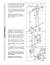
...). Slide the Rear Seat Frame (100) onto the indicated 5/16" x 2 1/2" Carriage Bolts (1) in steps 1-5. 6. Press a 2" Square Inner Cap (27) into the end 4 of Weights (25) until step 8 is complete. 5 56 8 3 6 1 100 11 3 3 1 82 5 Pin Grooves 25 25 19 5-Bracket 4-Bracket Pin Grooves 19 7 4. Tighten all on the Top Frame. Attach the Top Frame (55) to the VKR Upright (74) and the Leg Press Upright (56...
...). Slide the Rear Seat Frame (100) onto the indicated 5/16" x 2 1/2" Carriage Bolts (1) in steps 1-5. 6. Press a 2" Square Inner Cap (27) into the end 4 of Weights (25) until step 8 is complete. 5 56 8 3 6 1 100 11 3 3 1 82 5 Pin Grooves 25 25 19 5-Bracket 4-Bracket Pin Grooves 19 7 4. Tighten all on the Top Frame. Attach the Top Frame (55) to the VKR Upright (74) and the Leg Press Upright (56...
User Manual
Page 9
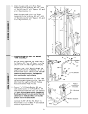
... a tight fit. Lubricate the 3/8" x 8" Bolt (59). Attach the upper ends of the Leg Press Arm (96). Press a 1" x 7/8" Plastic Bushing (90) onto each end of the Long Weight Guides (62) to the Stabilizer (5) with a 5/16" x 6" Bolt (60), two 1/2" x 3/4" Spacers (61), and a 5/16" Nylon Locknut (3). 9 61 60 73 3 61 60 3 55 62 FRAME ASSEMBLY ARM ASSEMBLY 10. Make sure that the pulleys are on the Press Frame (17). Press...
... a tight fit. Lubricate the 3/8" x 8" Bolt (59). Attach the upper ends of the Leg Press Arm (96). Press a 1" x 7/8" Plastic Bushing (90) onto each end of the Long Weight Guides (62) to the Stabilizer (5) with a 5/16" x 6" Bolt (60), two 1/2" x 3/4" Spacers (61), and a 5/16" Nylon Locknut (3). 9 61 60 73 3 61 60 3 55 62 FRAME ASSEMBLY ARM ASSEMBLY 10. Make sure that the pulleys are on the Press Frame (17). Press...
User Manual
Page 11
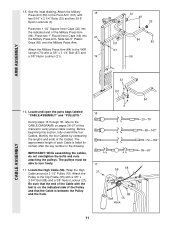
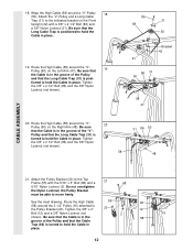
... the CABLE DIAGRAMS on the indicated side of each Cable is between the Pulley and the hook. 3 55 58 88 Ball 15 Hook 84 23-79" 58-147" 72-194" 99-63" 11 IMPORTANT: While assembling the cables, do not overtighten the bolts and nuts attaching the pulleys. Attach the Pulley to verify proper cable routing. Attach the Military 15 Press Arm (84) to the VKR Upright...
... the CABLE DIAGRAMS on the indicated side of each Cable is between the Pulley and the hook. 3 55 58 88 Ball 15 Hook 84 23-79" 58-147" 72-194" 99-63" 11 IMPORTANT: While assembling the cables, do not overtighten the bolts and nuts attaching the pulleys. Attach the Pulley to verify proper cable routing. Attach the Military 15 Press Arm (84) to the VKR Upright...
User Manual
Page 12
... Pulley Bracket (20) to hold the Cable in place. 19. Route the High Cable 55 66 (58) around a "V"-Pulley 18 (50). Wrap the High Cable (58) around the 3 1/2" Pulley (15) attached to hold the Cable in place. 12 tioned to the Pulley Bracket (20). Tighten the 3/8" x 2 1/2" Bolt (86) and the 3/8" Nylon Locknut (not shown). 58 31 86 50 48 CABLE ASSEMBLY 21. 18. Tighten the 3/8" x 2 1/2" Bolt...
... Pulley Bracket (20) to hold the Cable in place. 19. Route the High Cable 55 66 (58) around a "V"-Pulley 18 (50). Wrap the High Cable (58) around the 3 1/2" Pulley (15) attached to hold the Cable in place. 12 tioned to the Pulley Bracket (20). Tighten the 3/8" x 2 1/2" Bolt (86) and the 3/8" Nylon Locknut (not shown). 58 31 86 50 48 CABLE ASSEMBLY 21. 18. Tighten the 3/8" x 2 1/2" Bolt...
User Manual
Page 15
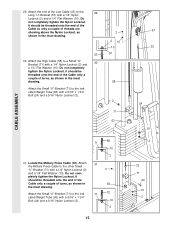
...1/4" Flat Washer (10). CABLE ASSEMBLY 29. Attach 31 the Military Press Cable to the indi- 71 72 cated Weight Tube (63) with a 1/4" Nylon Locknut (2) and 30 a 1/4" Flat Washer (10). pletely tighten the Nylon Locknut. Attach the Small "U"-Bracket (71) to the other Small "U"-Bracket (71) with a 5/16" x 1 3/4" Bolt (24) and a 5/...the Cable only a couple of turns, as shown in the inset drawing. Do not com- Do not completely tighten the Nylon Locknut. Locate the Military Press Cable (72). It should be threaded onto the end of the Cable only a couple of turns,...
...1/4" Flat Washer (10). CABLE ASSEMBLY 29. Attach 31 the Military Press Cable to the indi- 71 72 cated Weight Tube (63) with a 1/4" Nylon Locknut (2) and 30 a 1/4" Flat Washer (10). pletely tighten the Nylon Locknut. Attach the Small "U"-Bracket (71) to the other Small "U"-Bracket (71) with a 5/16" x 1 3/4" Bolt (24) and a 5/...the Cable only a couple of turns, as shown in the inset drawing. Do not com- Do not completely tighten the Nylon Locknut. Locate the Military Press Cable (72). It should be threaded onto the end of the Cable only a couple of turns,...
User Manual
Page 18
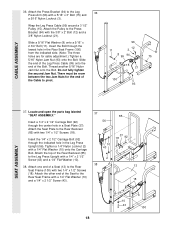
.... Slide the end of the Leg Press Cable (99) onto the end of the Seat to the Rear Seat Frame with a 1/4" Flat Washer (10) onto the Carriage Bolt. Locate and open the parts bag labeled "SEAT ASSEMBLY." Attach the Seat Plate to the Press Bracket (94) with two 1/4" x 1/2" Screws (18). Insert the 1/4" x 2 1/2" Carriage Bolt (92) through the center hole in the Leg Press Upright (56). Tighten a 1/4" Nylon Locknut (2) with a 1/4" Flat Washer...
.... Slide the end of the Leg Press Cable (99) onto the end of the Seat to the Rear Seat Frame with a 1/4" Flat Washer (10) onto the Carriage Bolt. Locate and open the parts bag labeled "SEAT ASSEMBLY." Attach the Seat Plate to the Press Bracket (94) with two 1/4" x 1/2" Screws (18). Insert the 1/4" x 2 1/2" Carriage Bolt (92) through the center hole in the Leg Press Upright (56). Tighten a 1/4" Nylon Locknut (2) with a 1/4" Flat Washer...

User Manual
Page 19
...). Press a 1 1/2" Square Inner Cap (32) into the Leg Lever (29). 41 Lubricate the 5/16" x 2 1/4" Bolt (33). Attach the Front Backrest (41) to the Front Seat Frame (36) with two 1/4" x 1/2" Screws (18). Rest the Front Seat Frame (36) on the indi- 42 cated pin in the Seat Plate (37). Attach 40 the Seat Plate to the Seat (13) with the Bolt and a 5/16" Nylon Locknut (3). SEAT ASSEMBLY...
...). Press a 1 1/2" Square Inner Cap (32) into the Leg Lever (29). 41 Lubricate the 5/16" x 2 1/4" Bolt (33). Attach the Front Backrest (41) to the Front Seat Frame (36) with two 1/4" x 1/2" Screws (18). Rest the Front Seat Frame (36) on the indi- 42 cated pin in the Seat Plate (37). Attach 40 the Seat Plate to the Seat (13) with the Bolt and a 5/16" Nylon Locknut (3). SEAT ASSEMBLY...
User Manual
Page 21
... USE THE HOME GYM SYSTEM, beginning on page 22 of the remaining parts will need to the Front Upright (42) under the "WEIDER" nameplate as shown. 46 WEIDER Nameplate 42 PRO 9640 Decal 47. The use of this manual for proper cable routing. IMPORTANT: If the cables are not properly installed, they may be explained in the cables, you will be damaged when heavy weight is used. See the CABLE DIAGRAMS...
... USE THE HOME GYM SYSTEM, beginning on page 22 of the remaining parts will need to the Front Upright (42) under the "WEIDER" nameplate as shown. 46 WEIDER Nameplate 42 PRO 9640 Decal 47. The use of this manual for proper cable routing. IMPORTANT: If the cables are not properly installed, they may be explained in the cables, you will be damaged when heavy weight is used. See the CABLE DIAGRAMS...
User Manual
Page 22
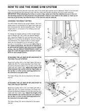
... PULLEY STATION Attach the Lat Bar (54) to the cables and pulleys, the amount of either weight stack, insert a Weight Pin (26) under the desired Weight (25). Use the WEIGHT RESISTANCE CHART on page 24 to the Low Cable (23) with a Cable Clip (53). The Nylon Strap (39) can be attached between the Lat Bar and the Low Cable with two Cable Clips. HOW TO USE THE HOME GYM SYSTEM The instructions below describe how each exercise...
... PULLEY STATION Attach the Lat Bar (54) to the cables and pulleys, the amount of either weight stack, insert a Weight Pin (26) under the desired Weight (25). Use the WEIGHT RESISTANCE CHART on page 24 to the Low Cable (23) with a Cable Clip (53). The Nylon Strap (39) can be attached between the Lat Bar and the Low Cable with two Cable Clips. HOW TO USE THE HOME GYM SYSTEM The instructions below describe how each exercise...

User Manual
Page 23
... Leg Press Arm (96). Attach the Seat Frame to the Eyebolt (35) with a Cable Clip (53). ATTACHING THE LEG LEVER TO THE LOW PULLEY STATION To use the Leg Lever (29), the seat must be attached to the front upright (see ATTACHING AND REMOVING THE SEAT above). First, be sure that the chain is not attached to the Short Cable (23) with a Cable Clip. ADJUSTING THE LEG PRESS PLATE Remove the Press Pin (97) from the Seat...
... Leg Press Arm (96). Attach the Seat Frame to the Eyebolt (35) with a Cable Clip (53). ATTACHING THE LEG LEVER TO THE LOW PULLEY STATION To use the Leg Lever (29), the seat must be attached to the front upright (see ATTACHING AND REMOVING THE SEAT above). First, be sure that the chain is not attached to the Short Cable (23) with a Cable Clip. ADJUSTING THE LEG PRESS PLATE Remove the Press Pin (97) from the Seat...
User Manual
Page 24
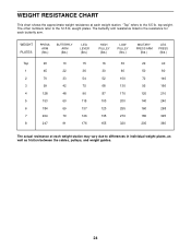
... 268 180 325 205 360 The actual resistance at each weight station. The butterfly arm resistance listed is the resistance for each butterfly arm. WEIGHT RESISTANCE CHART This chart shows the approximate weight resistance at each weight station may vary due to differences in individual weight plates, as well as friction between the cables, pulleys, and weight guides. 24 top weight. The other numbers refer to the 6.5 lb. "Top" refers to...
... 268 180 325 205 360 The actual resistance at each weight station. The butterfly arm resistance listed is the resistance for each butterfly arm. WEIGHT RESISTANCE CHART This chart shows the approximate weight resistance at each weight station may vary due to differences in individual weight plates, as well as friction between the cables, pulleys, and weight guides. 24 top weight. The other numbers refer to the 6.5 lb. "Top" refers to...
User Manual
Page 25
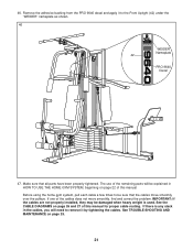
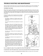
... of this manual. 25 Remove the cable and re-install it may have become twisted. Do not use the home gym system. If any slack is first used. Remove the 3/8" Nylon Locknut (21) and the 3/8" x 2" Bolt (12) from the Rear Seat Frame. If the cables need to be lifted off the pulleys often, it . If there is slack in the cables before resistance is in the Rear Seat Frame...
... of this manual. 25 Remove the cable and re-install it may have become twisted. Do not use the home gym system. If any slack is first used. Remove the 3/8" Nylon Locknut (21) and the 3/8" x 2" Bolt (12) from the Rear Seat Frame. If the cables need to be lifted off the pulleys often, it . If there is slack in the cables before resistance is in the Rear Seat Frame...
User Manual
Page 28
The KEY NUMBER and DESCRIPTION of the part(s) (see the front cover of this manual). The MODEL NUMBER of the product (WEIDER® PRO 9640 Home Gym System). 3. The SERIAL NUMBER of the product (see the PART LIST and EXPLODED DRAWING attached at 1-800-999-3756, Monday through Friday, 6 a.m. The NAME of the product (WESY96400). 2. To help us assist you, please be prepared to give the following information: 1. Part No...
The KEY NUMBER and DESCRIPTION of the part(s) (see the front cover of this manual). The MODEL NUMBER of the product (WEIDER® PRO 9640 Home Gym System). 3. The SERIAL NUMBER of the product (see the PART LIST and EXPLODED DRAWING attached at 1-800-999-3756, Monday through Friday, 6 a.m. The NAME of the product (WESY96400). 2. To help us assist you, please be prepared to give the following information: 1. Part No...
User Manual
Page 33
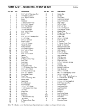
... x 3" Bolt 3 1/2" Low Pulley VKR Backrest VKR Armrest Left VKR Arm Right VKR Arm 1/4" x 2" Machine Screw Handle 5" Plastic Grip Military Press Arm Rear Backrest 3/8" x 2 1/2" Bolt #8 x 1/2" Self-tapping Screw 3/8" x 3 3/4" Bolt 1 1/8" x 2 1/2" Plastic Bushing 1" x 7/8" Plastic Bushing Rubber Bumper 1/4" x 2 1/2" Carriage Bolt 5/16" Nylon Jam Nut Press Bracket Leg Press Plate Leg Press Arm Press Pin Bushing Leg Press Cable Rear Seat Frame Pivot Arm User's Manual Exercise Poster Note: "#" indicates a non-illustrated part. PART LIST-Model No. WESY96400 R1296A Key No. Specifications are...
... x 3" Bolt 3 1/2" Low Pulley VKR Backrest VKR Armrest Left VKR Arm Right VKR Arm 1/4" x 2" Machine Screw Handle 5" Plastic Grip Military Press Arm Rear Backrest 3/8" x 2 1/2" Bolt #8 x 1/2" Self-tapping Screw 3/8" x 3 3/4" Bolt 1 1/8" x 2 1/2" Plastic Bushing 1" x 7/8" Plastic Bushing Rubber Bumper 1/4" x 2 1/2" Carriage Bolt 5/16" Nylon Jam Nut Press Bracket Leg Press Plate Leg Press Arm Press Pin Bushing Leg Press Cable Rear Seat Frame Pivot Arm User's Manual Exercise Poster Note: "#" indicates a non-illustrated part. PART LIST-Model No. WESY96400 R1296A Key No. Specifications are...


