
Weider Pro 9640 Support Question
Weider Pro 9640 Support Question
Find answers below for this question about Weider Pro 9640.Need a Weider Pro 9640 manual? We have 1 online manual for this item!
Question posted by djr1418 on August 11th, 2014
Having Trouble Routing Cable For The Fly Machine Part.
The person who posted this question about this Weider product did not include a detailed explanation. Please use the "Request More Information" button to the right if more details would help you to answer this question.
Current Answers
Related Weider Pro 9640 Manual Pages
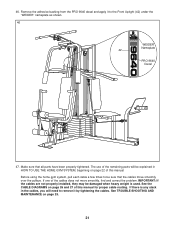
User Manual - Page 2
.... Some states do not allow limitations on how long an implied warranty lasts. ICON HEALTH & FITNESS, INC., 1500 S. 1000 W., LOGAN, UT 84321-9813
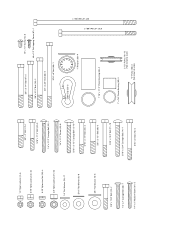
2 WEIDER is a registered trademark of...4 ASSEMBLY 5 HOW TO USE THE HOME GYM SYSTEM 22 WEIGHT RESISTANCE CHART 24 TROUBLE-SHOOTING AND MAINTENANCE 25 CABLE DIAGRAMS 26 ORDERING REPLACEMENT PARTS Back Cover
Note: A PART IDENTIFICATION CHART and a ...
User Manual - Page 3

... on a level surface. Keep your physician. Keep small children and pets away from moving parts. Replace any exercise program, consult your hands away from the home gym system when performing an exercise that the cables are raised. This is the responsibility of all parts often. It is especially important for home use the...
User Manual - Page 5
...One (1) phillips screwdriver
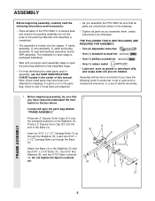
• One (1) rubber mallet • Lubricant, such as you assemble the PRO 9640 be more convenient if you have read the following tools: A socket set, a set of the Base...Press a 2" Square Inner Cap (27) into five stages: 1) frame assembly, 2) arm assembly, 3) cable and pulley assembly, 4) seat and backrest assembly, and 5) VKR assembly.
Insert two 5/16" x 2...
User Manual - Page 10
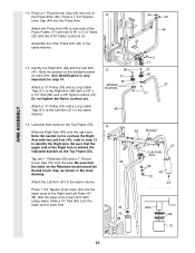
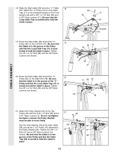
...17) with the Left Arm (47); Note the position of each Arm. Attach a "V"-Pulley (50) and a Long Cable Trap (31) to the Left Arm (47) in the same manner.
46
3
17
13. Lubricate both axles on ... Locknut yet.
13
86
31
50 Welded Brackets
31 50
47 21
Attach a "V"-Pulley (50) and a Long Cable
Trap (31) to the Right Arm (48) with soapy water. Be sure that
48
the teeth on the Top...
User Manual - Page 11
... Arm. Press two 1" Round Inner Caps (49) into
the indicated end of each Cable is between the Pulley
and the hook.
3
55
58
88
Ball
15
Hook
84
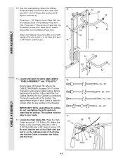
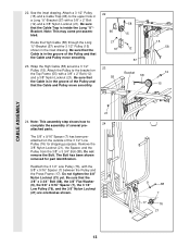
...Cables. Locate and open the parts bags labeled "CABLE ASSEMBLY" and "PULLEYS."
16
During steps 16 through 36, refer to the CABLE DIAGRAMS on the indicated side of the Cables. Before beginning this manual to verify proper cable routing...
User Manual - Page 12
... the "V"- Tighten
the 3/8" x 2 1/2" Bolt (86) and the 3/8" Nylon
Locknut (not shown).
86 31
58 50
Bracket 42 21
86 31 50
58 47
20. Route the High Cable (58) around the "V"-
20
Pulley (50) on the Front
Upright (42) with the 5/16" x 5" Bolt (68) and a
68
5/16" Nylon Locknut (3). Do not overtighten...
User Manual - Page 13
... (66) to complete the assembly of the 3 1/2" Low Pulley (76) for part identification. Be sure that the Cable Trap is inside the Long "U"Bracket. Route the High Cable (58) through the Long "U"-Bracket (57) and the 3 1/2" Pulley (15) shown in a Long "U"-Bracket (57) with a 3/8" x 2" Bolt (12) and a 3/8" Nylon Locknut (21). Do not remove...
User Manual - Page 14
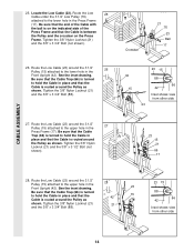
... (76)
attached to the upper hole in place and that the
15 42
Cable is turned to hold the Cable in the Front Upright (42).
Be sure that the Cable Trap (66) is routed around the Pulley as shown. Route the Low Cable (23) around the 3 1/2" Pulley (15) attached to the lower hole in
place and...
User Manual - Page 15
...71 63
58 71
10 2
31. pletely tighten the Nylon Locknut. It should be threaded onto the end of the
Cable so only a couple of turns, as shown in the inset
drawing. Attach the Small "U"-Bracket (71) to a Small...inset drawing.
23
30. It should be
threaded onto the end of the Cable only a
couple of the Low Cable (23) to the indi-
71
72
cated Weight Tube (63) with a 1/4" Nylon Locknut...
User Manual - Page 16
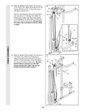
...
16 Be sure that the Nylon Locknut is on the Stabilizer (5) with a 3/8" x 2" Bolt (12) and a 3/8" Nylon Locknut (21). Be sure that the Cable Trap is turned to the Top Frame (55) with the 3/8" x 3 3/4" Bolt (88), a 3/8" Flat Washer (9), and a 3/8" Nylon Locknut (21).
See the inset drawing. Attach the Pulley ...
User Manual - Page 17
...). Attach the Pulley to pivot.
15 57 72
21 57
11 8
15 A 66 12 B 101
93 72
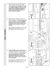
CABLE ASSEMBLY
35. Tighten a 5/16" Nylon Jam Nut (93) onto the Bolt. 34. See inset drawing A. assembled.)
Route the Military Press Cable (72) through the Pivot Arm (101) from the indicated side.
Be
sure that the...
User Manual - Page 18
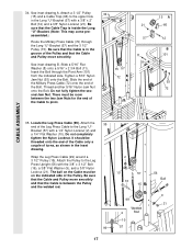
...37 18
92
2
38
13
18
10 43
100
18 There must be room between the two Jam Nuts for cable adjustment.) Tighten a 5/16" Nylon Jam Nut (93) onto the Bolt. Thread another 5/16" Nylon Jam ... fully tighten the second Jam Nut. Wrap the Leg Press Cable (99) around a 3 1/2" Pulley (15). Slide the end of the Leg Press Cable (99) onto the end of the Cable to pivot.
96
12
11
3
8 99
94
75
15...
User Manual - Page 20
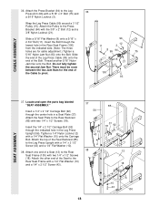
... the VKR Upright (74) with two 1/4" x 2 1/2" Screws (43) and two 1/4" Flat Washers (10).
Attach a VKR Armrest (78) to the Right VKR Arm (80) with two 1/4" x 2" Machine Screws (81) and two 1/4" Flat Washers (10). Attach the Left VKR Arm (79) and the Right VKR Arm (80) to the VKR Upright (74) with...
User Manual - Page 21
...tightened. If there is used. The use of the cables does not move smoothly over the pulleys. See TROUBLE-SHOOTING AND MAINTENANCE on page 25.
21 Make sure that the cables move smoothly, find and correct the problem. If ..., beginning on page 26 and 27 of this manual for proper cable routing. 46. Remove the adhesive backing from the PRO 9640 decal and apply it by tightening the...
User Manual - Page 22
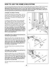
... Weight
(25). tance at each exercise. CHANGING THE WEIGHT SETTING
The PRO 9640 features two weight stacks.
Adjust the... length of 12.5 pounds. If there is any slack in the correct starting position for the exercise to be attached between the Lat Bar and the Low Cable so the Lat Bar is in the cables or chain as an exercise...
User Manual - Page 23

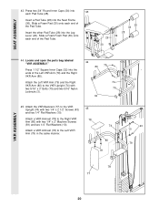
... Plate (95) with the 5/16" x 2 3/4" Carriage Bolt (14) and the Seat Knob (40). For some exercises, the Seat (13) must be sure that the chain is not attached to the leg lever. ATTACHING AND REMOVING THE ...29
35
53 23
Welded Tube
96
95 97
23 First, be attached to the Eyebolt (35) with a Cable Clip (53). Lift the Seat Frame off the Front Upright (42). Attach one end of the Chain to ...
User Manual - Page 25
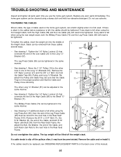
...; See drawing 1. Tighten the 1/4" Nylon Locknut (2) that connects the end of the weight stack. The Leg Press Cable (99) can be tightened. If a cable tends to be tightened in the same manner.
• See drawing 2. TROUBLE-SHOOTING AND MAINTENANCE
Inspect and tighten all parts each time you use solvents. Replace any slack is...
User Manual - Page 26
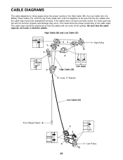
The insets show the proper routing of the cable traps. If the cables have been assembled correctly. The cable traps should be sure that the four cables and the cable traps have not been correctly routed, the home gym system will not come off the pulleys.
CABLE DIAGRAMS
The cable diagrams on these pages show the proper positioning of the...
User Manual - Page 31
... Washer (8)-9
3/8" Flat Washer (9)-6
3/8" x 1 3/4" Bolt (24)-2 1/4" x 2" Carriage Bolt (38)-1 1/4" x 2" Machine Screw (81)-5
3/8" x 2" Bolt (12)-7 5/16" x 2 1/4" Bolt (33)-3 1/4" x 2 1/2" Carriage Bolt ... #8 x 1/2" Self-tapping Screw (87)-1
3/8" x 3 3/4" Bolt (88)-5 5/16" x 5" Bolt (68)-1
Cable Clip (53)-3
1" Retainer (69)-4
1 1/8" x 2 1/2" Plastic Bushing (89)-2
1" x 7/8" Plastic Bushing (90...
User Manual - Page 33
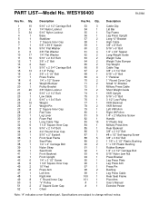
... 2" Machine Screw Handle 5" Plastic Grip Military Press Arm Rear Backrest 3/8" x 2 1/2" Bolt #8 x 1/2" Self-tapping Screw 3/8" x 3 3/4" Bolt 1 1/8" x 2 1/2" Plastic Bushing 1" x 7/8" Plastic Bushing Rubber Bumper 1/4" x 2 1/2" Carriage Bolt 5/16" Nylon Jam Nut Press Bracket Leg Press Plate Leg Press Arm Press Pin Bushing Leg Press Cable Rear Seat Frame Pivot Arm User's Manual Exercise Poster
Note...
Similar Questions

I'm Looking To Order Complete Cables To The Weider Pro 9940
(Posted by Hef2324 1 year ago)

Where Do I Go To See Replacement Parts For The Joe Weider 9640 Pro?
I am looking for a replacement cable for the leg lift on my weider 9640 pro.
I am looking for a replacement cable for the leg lift on my weider 9640 pro.
(Posted by frankuchler 3 years ago)

Where Can I Find A Short Cable For A Weider Pro 9930?
where can I find a short cable for a weider pro 9930?
where can I find a short cable for a weider pro 9930?
(Posted by pastorglb2 4 years ago)

How To Install Cable And Pulley On Weider Pro 4850
can you help me install new weider pro 4850 cable and pulley?
can you help me install new weider pro 4850 cable and pulley?
(Posted by verrolburnett 8 years ago)

Cable Assembly
how do I run the cable assembly on the weider pro 4250?the diagrams seem to stop mid air.
how do I run the cable assembly on the weider pro 4250?the diagrams seem to stop mid air.
(Posted by jawsaw0328 8 years ago)