
User Manual
Page 2
...of purchase. ICON is not responsible or liable for which vary from the date of purchase. You may not apply to you. WEIDER is a registered trademark of incidental or consequential damages. Some states do not allow limitations on how long an implied warranty lasts. TABLE... OF CONTENTS LIMITED WARRANTY 2 IMPORTANT PRECAUTIONS 3 BEFORE YOU BEGIN 4 ASSEMBLY 5 HOW TO USE THE HOME GYM SYSTEM 22 WEIGHT RESISTANCE CHART 24 TROUBLE-SHOOTING AND MAINTENANCE 25 CABLE DIAGRAMS 26 ORDERING REPLACEMENT PARTS ...
...of purchase. ICON is not responsible or liable for which vary from the date of purchase. You may not apply to you. WEIDER is a registered trademark of incidental or consequential damages. Some states do not allow limitations on how long an implied warranty lasts. TABLE... OF CONTENTS LIMITED WARRANTY 2 IMPORTANT PRECAUTIONS 3 BEFORE YOU BEGIN 4 ASSEMBLY 5 HOW TO USE THE HOME GYM SYSTEM 22 WEIGHT RESISTANCE CHART 24 TROUBLE-SHOOTING AND MAINTENANCE 25 CABLE DIAGRAMS 26 ORDERING REPLACEMENT PARTS ...
User Manual
Page 4
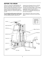
..., Monday through Friday, 6 a.m. For your cardiovascular system, the PRO 9640 will help us assist you want. Width: 89 in . The model number is to the WEIDER® PRO 9640 (see the front cover of the body. Mountain Time (excluding holidays...ASSEMBLED DIMENSIONS: Height: 76 in . Length: 64 in. To help you to develop every major muscle group of this manual carefully before calling. The PRO 9640 offers a selection of weight stations designed to achieve the specific results you , please note the product model number and serial number before using the WEIDER® PRO 9640...
..., Monday through Friday, 6 a.m. For your cardiovascular system, the PRO 9640 will help us assist you want. Width: 89 in . The model number is to the WEIDER® PRO 9640 (see the front cover of the body. Mountain Time (excluding holidays...ASSEMBLED DIMENSIONS: Height: 76 in . Length: 64 in. To help you to develop every major muscle group of this manual carefully before calling. The PRO 9640 offers a selection of weight stations designed to achieve the specific results you , please note the product model number and serial number before using the WEIDER® PRO 9640...
User Manual
Page 5
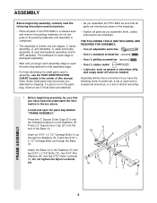
... 5/16" x 2 1/2" Carriage Bolts up through the Base (4). The hardware for each assembly stage to see if it has been pre-attached. • As you assemble the PRO 9640 be sure that you have read the following tools: A socket set, a set of...(27) into five stages: 1) frame assembly, 2) arm assembly, 3) cable and pulley assembly, 4) seat and backrest assembly, and 5) VKR assembly. Attach the Base (4) to do not dispose of the PRO 9640 in a cleared area and remove the packing materials; ASSEMBLY Before beginning assembly, carefully read and understand the information in...
... 5/16" x 2 1/2" Carriage Bolts up through the Base (4). The hardware for each assembly stage to see if it has been pre-attached. • As you assemble the PRO 9640 be sure that you have read the following tools: A socket set, a set of...(27) into five stages: 1) frame assembly, 2) arm assembly, 3) cable and pulley assembly, 4) seat and backrest assembly, and 5) VKR assembly. Attach the Base (4) to do not dispose of the PRO 9640 in a cleared area and remove the packing materials; ASSEMBLY Before beginning assembly, carefully read and understand the information in...
User Manual
Page 6
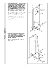
...) and the Leg Press Upright (56) onto the indicated 5/16" x 2 1/2" Carriage Bolts (1) in the Base (4). 3 Hand-tighten a 5/16" Nylon Locknut (3) onto each Carriage Bolt. FRAME ASSEMBLY 4 1 42 6 3 6 Do not tighten the Nylon Locknuts yet. 2.
...) and the Leg Press Upright (56) onto the indicated 5/16" x 2 1/2" Carriage Bolts (1) in the Base (4). 3 Hand-tighten a 5/16" Nylon Locknut (3) onto each Carriage Bolt. FRAME ASSEMBLY 4 1 42 6 3 6 Do not tighten the Nylon Locknuts yet. 2.
User Manual
Page 7
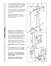
... (56) with two 5/16" x 2 3/4" Bolts (11), two 5/16" Flat Washers (8), and two 5/16" Nylon Locknuts (3). 55 11 49 8 44 3 44 Crossbar 3 56 42 74 FRAME ASSEMBLY 5. Slide the Rear Seat Frame (100) onto the indicated 5/16" x 2 1/2" Carriage Bolts (1) in steps 1-5. 6. Attach the Handle (82) to the Leg Press Upright (56) with...
... (56) with two 5/16" x 2 3/4" Bolts (11), two 5/16" Flat Washers (8), and two 5/16" Nylon Locknuts (3). 55 11 49 8 44 3 44 Crossbar 3 56 42 74 FRAME ASSEMBLY 5. Slide the Rear Seat Frame (100) onto the indicated 5/16" x 2 1/2" Carriage Bolts (1) in steps 1-5. 6. Attach the Handle (82) to the Leg Press Upright (56) with...
User Manual
Page 8
...) into the stack of the holes in the Weight Guides are at the top, as shown. 65 Pin 63 62 Lubricate 64 Pin Grooves FRAME ASSEMBLY 25 8. Be sure that the pin on the Weight 73 Tube is sit- Insert both Long Weight Guides (62) into the stack of the other...
...) into the stack of the holes in the Weight Guides are at the top, as shown. 65 Pin 63 62 Lubricate 64 Pin Grooves FRAME ASSEMBLY 25 8. Be sure that the pin on the Weight 73 Tube is sit- Insert both Long Weight Guides (62) into the stack of the other...
User Manual
Page 9
... Stabilizer (5) with a 5/16" x 6" Bolt (60), two 1/2" x 3/4" Spacers (61), and a 5/16" Nylon Locknut (3). 9 61 60 73 3 61 60 3 55 62 FRAME ASSEMBLY ARM ASSEMBLY 10. Attach the Press Frame (17) to the Top Frame (55) with the Bolt and a 3/8" Nylon Locknut (21). Attach the upper ends of the Short...Base. Do not overtighten the Nylon Locknut. Note: This will be on the Press Frame (17). Locate and open the parts bag labeled 10 "ARM ASSEMBLY." Press a 1" x 7/8" Plastic Bushing (90) onto each end of the indicated tube in each end of the Leg Press Arm (96). Slide ...
... Stabilizer (5) with a 5/16" x 6" Bolt (60), two 1/2" x 3/4" Spacers (61), and a 5/16" Nylon Locknut (3). 9 61 60 73 3 61 60 3 55 62 FRAME ASSEMBLY ARM ASSEMBLY 10. Attach the Press Frame (17) to the Top Frame (55) with the Bolt and a 3/8" Nylon Locknut (21). Attach the upper ends of the Short...Base. Do not overtighten the Nylon Locknut. Note: This will be on the Press Frame (17). Locate and open the parts bag labeled 10 "ARM ASSEMBLY." Press a 1" x 7/8" Plastic Bushing (90) onto each end of the indicated tube in each end of the Leg Press Arm (96). Slide ...
User Manual
Page 10
... a Long Cable Trap (31) to confuse the Right Arm with two 5/16" x 2 1/2" Bolts (22) and two 5/16" Nylon Locknuts (3). 22 Assemble the other Press Arm (46) in the same manner. ARM ASSEMBLY 12. Press a 1 3/4" Square Inner Cap (44) into the lower ends of each Arm. 44 45 55 Bracket 47 Lubricate Axle...
... a Long Cable Trap (31) to confuse the Right Arm with two 5/16" x 2 1/2" Bolts (22) and two 5/16" Nylon Locknuts (3). 22 Assemble the other Press Arm (46) in the same manner. ARM ASSEMBLY 12. Press a 1 3/4" Square Inner Cap (44) into the lower ends of each Arm. 44 45 55 Bracket 47 Lubricate Axle...
User Manual
Page 11
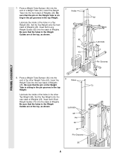
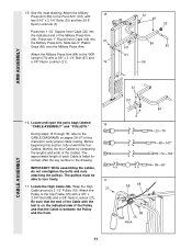
...of the Cable with a 3/8" x 3 1/4" Bolt (67) and a 3/8" Nylon Locknut (21). 74 32 49 32 101 84 83 67 56 ARM ASSEMBLY CABLE ASSEMBLY 33 101 16. Attach the Pulley to verify proper cable routing. Attach the Military 15 Press Arm (84) to the CABLE DIAGRAMS on the indicated... the key number in the drawing. Identify the four Cables by comparing the lengths and ends of the Military Press Arm (84). IMPORTANT: While assembling the cables, do not overtighten the bolts and nuts attaching the pulleys. Wrap the High 21 Cable around a 3 1/2" Pulley (15). The ...
...of the Cable with a 3/8" x 3 1/4" Bolt (67) and a 3/8" Nylon Locknut (21). 74 32 49 32 101 84 83 67 56 ARM ASSEMBLY CABLE ASSEMBLY 33 101 16. Attach the Pulley to verify proper cable routing. Attach the Military 15 Press Arm (84) to the CABLE DIAGRAMS on the indicated... the key number in the drawing. Identify the four Cables by comparing the lengths and ends of the Military Press Arm (84). IMPORTANT: While assembling the cables, do not overtighten the bolts and nuts attaching the pulleys. Wrap the High 21 Cable around a 3 1/2" Pulley (15). The ...
User Manual
Page 12
... (86) and a 3/8" Nylon Locknut (21). tioned to move freely. Tighten the 3/8" x 2 1/2" Bolt (86) and the 3/8" Nylon Locknut (not shown). 58 31 86 50 48 CABLE ASSEMBLY 21. See the inset drawing. Tighten the 3/8" x 2" 20 12 Bolt (12) and a 3/8" Nylon Locknut (not shown). Route the High Cable 55 66 (58) around a "V"-Pulley...
... (86) and a 3/8" Nylon Locknut (21). tioned to move freely. Tighten the 3/8" x 2 1/2" Bolt (86) and the 3/8" Nylon Locknut (not shown). 58 31 86 50 48 CABLE ASSEMBLY 21. See the inset drawing. Tighten the 3/8" x 2" 20 12 Bolt (12) and a 3/8" Nylon Locknut (not shown). Route the High Cable 55 66 (58) around a "V"-Pulley...
User Manual
Page 13
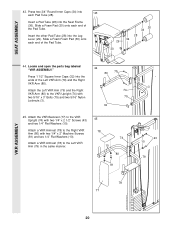
... a 3/8" Nylon Locknut (21). Attach the Pulley to the bracket on the outside of the 3 1/2" Low Pulley (76) for part identification. Note: This assembly step shows how to the upper hole in a Long "U"-Bracket (57) with the 5/8" x 9/16" Spacer (7) between the Pulley and the Press Frame (17...). Attach a 3 1/2" Pulley (15) and a Cable Trap (66) to complete the assembly of the Pulley and that the 3/8" x 3 3/4" Bolt (88), the 3/8" Flat Washer (9), the 5/8" x 9/16" Spacer (7), the 3 1/2" Low Pulley (76), and ...
... a 3/8" Nylon Locknut (21). Attach the Pulley to the bracket on the outside of the 3 1/2" Low Pulley (76) for part identification. Note: This assembly step shows how to the upper hole in a Long "U"-Bracket (57) with the 5/8" x 9/16" Spacer (7) between the Pulley and the Press Frame (17...). Attach a 3 1/2" Pulley (15) and a Cable Trap (66) to complete the assembly of the Pulley and that the 3/8" x 3 3/4" Bolt (88), the 3/8" Flat Washer (9), the 5/8" x 9/16" Spacer (7), the 3 1/2" Low Pulley (76), and ...
User Manual
Page 14
... the Pulley as shown. Route the Low Cable (23) around the 3 1/2" Pulley (15) attached to the upper hole in the 27 Press Frame (17). CABLE ASSEMBLY 25. Tighten the 3/8" Nylon Locknut (21) and the 3/8" x 3 3/4" Bolt (not shown). Route the Low Cable (23) around the 3 1/2" Pulley (15) attached to the upper hole...
... the Pulley as shown. Route the Low Cable (23) around the 3 1/2" Pulley (15) attached to the upper hole in the 27 Press Frame (17). CABLE ASSEMBLY 25. Tighten the 3/8" Nylon Locknut (21) and the 3/8" x 3 3/4" Bolt (not shown). Route the Low Cable (23) around the 3 1/2" Pulley (15) attached to the upper hole...
User Manual
Page 15
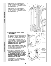
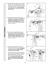
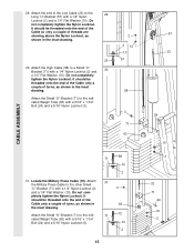
... 31 the Military Press Cable to the 29 Long "U"-Bracket (57) with a 1/4" Nylon Locknut (2) and a 1/4" Flat Washer (10). Locate the Military Press Cable (72). CABLE ASSEMBLY 29. It should be threaded onto the end of the Cable so only a couple of turns, as shown in 63 the inset drawing. Do not...
... 31 the Military Press Cable to the 29 Long "U"-Bracket (57) with a 1/4" Nylon Locknut (2) and a 1/4" Flat Washer (10). Locate the Military Press Cable (72). CABLE ASSEMBLY 29. It should be threaded onto the end of the Cable so only a couple of turns, as shown in 63 the inset drawing. Do not...
User Manual
Page 16
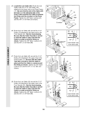
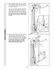
... Bracket 21 5 33. Be sure that the Cable Trap is turned to hold the Cable in place. 33 15 88 66 9 101 72 21 CABLE ASSEMBLY 16 Be sure that the Nylon Locknut is on the Stabilizer (5) with a 3/8" x 2" Bolt (12) and a 3/8" Nylon Locknut (21). Wrap the Long Cable (72) around a 3 1/2" Pulley...
... Bracket 21 5 33. Be sure that the Cable Trap is turned to hold the Cable in place. 33 15 88 66 9 101 72 21 CABLE ASSEMBLY 16 Be sure that the Nylon Locknut is on the Stabilizer (5) with a 3/8" x 2" Bolt (12) and a 3/8" Nylon Locknut (21). Wrap the Long Cable (72) around a 3 1/2" Pulley...
User Manual
Page 17
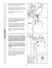
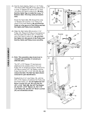
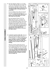
...) with a 1/4" Nylon Locknut (2) and a 1/4" Flat Washer (10). Be sure that the Cable is in the groove of the Bolt. Locate the Leg Press Cable (99). assembled.) Route the Military Press Cable (72) through the Pivot Arm (101) from the indicated side. Be sure that the Cable is inside the Long "U"-Bracket... 9 21 34. Attach a 3 1/2" Pulley 34 (15) and a Cable Trap (66) to pivot. 15 57 72 21 57 11 8 15 A 66 12 B 101 93 72 CABLE ASSEMBLY 35. See inset drawing B. Slide the end of the Military Press Cable (72) onto the end of the Pulley and that the Cable and Pulley...
...) with a 1/4" Nylon Locknut (2) and a 1/4" Flat Washer (10). Be sure that the Cable is in the groove of the Bolt. Locate the Leg Press Cable (99). assembled.) Route the Military Press Cable (72) through the Pivot Arm (101) from the indicated side. Be sure that the Cable is inside the Long "U"-Bracket... 9 21 34. Attach a 3 1/2" Pulley 34 (15) and a Cable Trap (66) to pivot. 15 57 72 21 57 11 8 15 A 66 12 B 101 93 72 CABLE ASSEMBLY 35. See inset drawing B. Slide the end of the Military Press Cable (72) onto the end of the Pulley and that the Cable and Pulley...
User Manual
Page 18
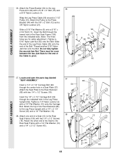
... Press Bracket (94) with two 1/4" x 1/2" Screws (18). Attach the Seat Plate to pivot. 96 12 11 3 8 99 94 75 15 21 100 93 SEAT ASSEMBLY 37. Attach one end of the Cable to the Rear Backrest (85) with the 3/8" x 2" Bolt (12) and a 3/8" Nylon Locknut (21). Slide a 5/16..." Flat Washer (8) onto a 5/16" x 2 3/4" Bolt (11). Locate and open the parts bag labeled "SEAT ASSEMBLY." Insert the 1/4" x 2 1/2" Carriage Bolt (92) through the lowest hole in the Rear Seat Frame (100) from the indicated side. (Note: The three holes are for...
... Press Bracket (94) with two 1/4" x 1/2" Screws (18). Attach the Seat Plate to pivot. 96 12 11 3 8 99 94 75 15 21 100 93 SEAT ASSEMBLY 37. Attach one end of the Cable to the Rear Backrest (85) with the 3/8" x 2" Bolt (12) and a 3/8" Nylon Locknut (21). Slide a 5/16..." Flat Washer (8) onto a 5/16" x 2 3/4" Bolt (11). Locate and open the parts bag labeled "SEAT ASSEMBLY." Insert the 1/4" x 2 1/2" Carriage Bolt (92) through the lowest hole in the Rear Seat Frame (100) from the indicated side. (Note: The three holes are for...

User Manual
Page 19
SEAT ASSEMBLY 39. The Backrest must be oriented as shown. 42 41 43 10 40. Attach the Leg Lever (29) to the Front Seat Frame (36) with ...
SEAT ASSEMBLY 39. The Backrest must be oriented as shown. 42 41 43 10 40. Attach the Leg Lever (29) to the Front Seat Frame (36) with ...
User Manual
Page 20
...). Attach the VKR Backrest (77) to the VKR Upright (74) with two 1/4" x 2 1/2" Screws (43) and two 1/4" Flat Washers (10). SEAT ASSEMBLY 43. Locate and open the parts bag labeled "VKR ASSEMBLY." Press 1 1/2" Square Inner Caps (32) into the Leg Lever (29). Attach a VKR Armrest (78) to the Right VKR Arm (80) with... a VKR Armrest (78) to the Left VKR Arm (79) in the same manner. 45 78 10 74 80 81 3 43 10 79 78 77 VKR ASSEMBLY 20 Press two 3/4" Round Inner Caps (34) into the Seat Frame (36). Insert a Pad Tube (28) into 43 each end of the Pad Tube. Slide...
...). Attach the VKR Backrest (77) to the VKR Upright (74) with two 1/4" x 2 1/2" Screws (43) and two 1/4" Flat Washers (10). SEAT ASSEMBLY 43. Locate and open the parts bag labeled "VKR ASSEMBLY." Press 1 1/2" Square Inner Caps (32) into the Leg Lever (29). Attach a VKR Armrest (78) to the Right VKR Arm (80) with... a VKR Armrest (78) to the Left VKR Arm (79) in the same manner. 45 78 10 74 80 81 3 43 10 79 78 77 VKR ASSEMBLY 20 Press two 3/4" Round Inner Caps (34) into the Seat Frame (36). Insert a Pad Tube (28) into 43 each end of the Pad Tube. Slide...
User Manual
Page 26
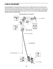
... of the High Cable (58), the Low Cable (23), the Military Press Cable (72), and the Leg Press Cable (99). If the cables have been assembled correctly. Use the diagrams to be positioned so that the cable traps do not touch or bind the cables.
... of the High Cable (58), the Low Cable (23), the Military Press Cable (72), and the Leg Press Cable (99). If the cables have been assembled correctly. Use the diagrams to be positioned so that the cable traps do not touch or bind the cables.
User Manual
Page 29
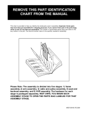
.... REMOVE THIS PART IDENTIFICATION CHART FROM THE MANUAL This chart is divided into five stages: 1) frame assembly, 2) arm assembly, 3) cable and pulley assembly, 4) seat and backrest assembly, and 5) VKR assembly. The second number refers to help you cannot find a part in parenthesis below each stage is packaged... separately. WAIT UNTIL YOU BEGIN EACH ASSEMBLY STAGE TO OPEN THE PARTS BAG LABELED FOR THAT ASSEMBLY STAGE. Please Note: The assembly is provided to the quantity needed for shipping purposes. The hardware for each part refers...
.... REMOVE THIS PART IDENTIFICATION CHART FROM THE MANUAL This chart is divided into five stages: 1) frame assembly, 2) arm assembly, 3) cable and pulley assembly, 4) seat and backrest assembly, and 5) VKR assembly. The second number refers to help you cannot find a part in parenthesis below each stage is packaged... separately. WAIT UNTIL YOU BEGIN EACH ASSEMBLY STAGE TO OPEN THE PARTS BAG LABELED FOR THAT ASSEMBLY STAGE. Please Note: The assembly is provided to the quantity needed for shipping purposes. The hardware for each part refers...


