
Weider Pro 9640 Support Question
Weider Pro 9640 Support Question
Find answers below for this question about Weider Pro 9640.Need a Weider Pro 9640 manual? We have 1 online manual for this item!
Current Answers
Answer #1: Posted by BusterDoogen on January 27th, 2018 9:57 AM
BusterDoogen

Member since:
October 30th, 2011 Points: 28,565,447

Member since:
October 30th, 2011 Points: 28,565,447
Go here for the manual.
I hope this is helpful to you!
Please respond to my effort to provide you with the best possible solution by using the "Acceptable Solution" and/or the "Helpful" buttons when the answer has proven to be helpful. Please feel free to submit further info for your question, if a solution was not provided. I appreciate the opportunity to serve you!
Related Weider Pro 9640 Manual Pages
User Manual - Page 2
... Remove the PART IDENTIFICATION CHART and the PART LIST/EXPLODED DRAWING before beginning assembly. LIMITED WARRANTY
ICON Health & Fitness, Inc. (ICON), warrants this product to be free from state to the... and service conditions, for which vary from defects in workmanship and material, under this manual. This warranty does not extend to any and all freight and other warranties and any...
User Manual - Page 4
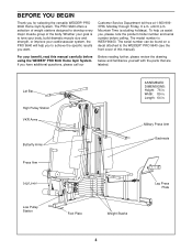
...9993756, Monday through Friday, 6 a.m. The model number is to the WEIDER® PRO 9640 (see the front cover of this manual carefully before calling. Width: 89 in . until 6 p.m. The serial number can be...Leg Press Plate
4 Lat Bar High Pulley Station VKR Arms
Butterfly Arms
ASSEMBLED DIMENSIONS: Height: 76 in. The PRO 9640 offers a selection of the body. BEFORE YOU BEGIN
Thank you have ...
User Manual - Page 5
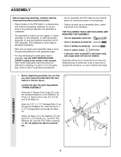
...assemble them, unless instructed to do not dispose of this manual. If a part is not in the parts bag, check to see if it has been pre-attached.
• As you assemble the PRO 9640... parts of ratchet wrenches. do otherwise. Before beginning assembly, be sure that all parts are oriented as grease or petroleum jelly,
and soapy water will be needed. Insert six 5/16" x 2 1/2" Carriage Bolts...
User Manual - Page 6
Hand-tighten four 5/16" Nylon Locknuts (3) onto the Carriage Bolts.
Do not tighten the
Nylon Locknuts yet.
FRAME ASSEMBLY
4 1
42 6
3
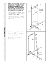
6 Press a 2" Square Inner Cap into the Front Upright (42). Do not tighten the Nylon Locknuts yet.
Attach the Rubber Bumper (91) to the Leg ...
User Manual - Page 7
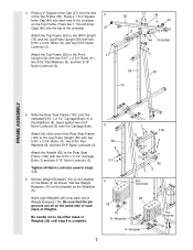
... (56) with two 5/16" x 2 3/4" Bolts (11),
two 5/16" Flat Washers (8), and two 5/16"
Nylon Locknuts (3).
55
11
49
8
44
3 44 Crossbar
3
56
42
74
FRAME ASSEMBLY
5. 4. Press a 1 3/4" Square
Inner Cap (44) into the end
4
of the Rear Seat Frame (100) to tip either stack of Weight Bumpers (19). Stack eight Weights...
User Manual - Page 8
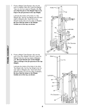
... the rear stack of the holes in the Weight Guides are at the top, as shown.
65
Pin 63
62
Lubricate 64
Pin Grooves
FRAME ASSEMBLY
25
8. Be
sure that the pin on the Weight Tube is sitting in the pin grooves in the top Weight.
Set the Top Weight onto...
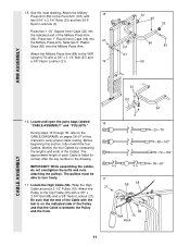
User Manual - Page 9
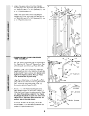
...Pin (97).
11. Locate and open the parts bag labeled
10
"ARM ASSEMBLY." The Leg Press Arm must be on this side
59-Lubricate
21
Welded Spacers... Nylon Locknut (3).
9
61
60
73
3 61 60
3 55
62
FRAME ASSEMBLY
ARM ASSEMBLY
10.
Align the welded tubes on each welded spacer on the side shown. The Plastic Bushings should fit on the Leg Press Plate
(95) with a 5/16" x 6" Bolt...
User Manual - Page 10
ARM ASSEMBLY
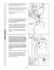
12. Do not tighten the Nylon Locknut yet.
13
86
31
50 Welded Brackets
31 50
47 21
Attach a "V"-Pulley (50)... (47). refer to step 13 to confuse the Right Arm with two 5/16" x 2 1/2" Bolts
(22) and two 5/16" Nylon Locknuts (3).
22 Assemble the other Press Arm (46) in the inset
drawing. Attach the Left Arm (47) in the same
48
manner.
14. Press 1 3/4" Square Inner Caps...
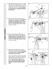
User Manual - Page 11
... of this section, fully unwind the four Cables.
See the inset drawing.
Before beginning this manual to the VKR
Upright (74) with the
ball is on pages 26-27 of each Cable...x 3 1/4" Bolt (67) and
a 3/8" Nylon Locknut (21).
74
32 49
32
101
84
83
67 56
ARM ASSEMBLY
CABLE ASSEMBLY
33 101
16. The pulleys must be
able to the Top Frame (55) with
two 5/16" x 2 1/4" Bolts ...
User Manual - Page 12
...
Bracket 42 21
86 31 50
58 47
20. Tighten
the 3/8" x 2 1/2" Bolt (86) and the 3/8" Nylon
Locknut (not shown).
58
31 86 50 48
CABLE ASSEMBLY
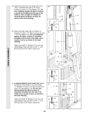
21. See the inset drawing. Wrap the High Cable (58) around the "V"-
20
Pulley (50) on the Front
Upright (42) with the 5/16" x 5" Bolt (68...
User Manual - Page 13
... shows how to complete the assembly of the Pulley and that the Cable is in the groove of the 3 1/2" Low Pulley (76) for part identification.
22. ...smoothly.
22
66 21 57
23 55
58 15
12 57
Bracket 58
15 58
12 15
CABLE ASSEMBLY
21
24. Do not remove the Bolt. Note: This may come pre-assembled. Attach the Pulley to the upper hole in the inset drawing. Remove the 3/8" Nylon Locknut (...
User Manual - Page 14
... that the Cable Trap (66) is turned
to hold the Cable in place and that the Cable is routed around
the Pulley as
shown. CABLE ASSEMBLY
25.
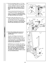
User Manual - Page 15
...) to the indicated Weight Tube (63) with a 5/16" x 1 3/4"
Bolt (24) and a 5/16" Nylon Locknut (3).
10
2
15
57 23
24
10 2
72 71
24 10 2 CABLE ASSEMBLY
29. Attach the end of threads are
showing above the Nylon Locknut, as shown in the inset
drawing.
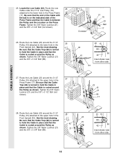
User Manual - Page 16
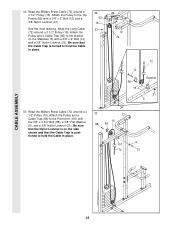
32. Attach the Pulley to hold the Cable in place.
33 15
88 66
9 101
72
21
CABLE ASSEMBLY
16 Be sure that the Nylon Locknut is on the Stabilizer (5) with a 3/8" x 2" Bolt (12) and a 3/8" Nylon Locknut (21). Wrap the Military Press Cable (72) around a 3 1/2" ...
User Manual - Page 17
...Cable to pivot.
15 57 72
21 57
11 8
15 A 66 12 B 101
93 72
CABLE ASSEMBLY
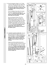
35. Attach the
35
end of the Bolt.
Wrap the Leg Press Cable (99) around a 3 ...1/2" Pulley (15). The ball on the indicated side of the Cable to the Long "U"- assembled.)
Route the Military Press Cable (72) through the Pivot Arm (101) from the indicated side. Slide a 5/16" Flat ...
User Manual - Page 21
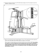
.... See TROUBLE-SHOOTING AND MAINTENANCE on page 26 and 27 of this manual. The use of the remaining parts will need to be explained in HOW TO USE THE HOME GYM SYSTEM, beginning on... "WEIDER" nameplate as shown.
46
WEIDER Nameplate 42 PRO 9640
Decal
47. See the CABLE DIAGRAMS on page 25.
21 Remove the adhesive backing from the PRO 9640 decal and apply it by tightening the cables. Make ...
User Manual - Page 22
...upper and lower pul-
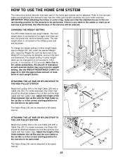
Refer to the exercise poster accompanying this manual to see how the home gym system should be set up for the exercise to be performed. IMPORTANT: When attaching ...Pin (26) under the desired Weight
(25). For some exercises, the Chain (52) should be performed. CHANGING THE WEIGHT SETTING
The PRO 9640 features two weight stacks. Adjust the length of the Chain between...
User Manual - Page 26
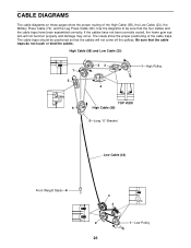
... the pulleys. Use the diagrams to be positioned so that the cable traps do not touch or bind the cables. If the cables have been assembled correctly. Be sure that the cables will not function properly and damage may occur.
User Manual - Page 28
...174; PRO 9640 Home Gym System).
3.
The KEY NUMBER and DESCRIPTION of the part(s) (see the front cover of this manual). ...Mountain Time (excluding holidays). The SERIAL NUMBER of the product (see the PART LIST and EXPLODED DRAWING attached at 1-800-999-3756, Monday through Friday, 6 a.m. Part No. 135891 F04109-C R1296A
Printed in Canada © 1996 ICON Health & Fitness...
User Manual - Page 29
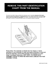
... below each stage is divided into five stages: 1) frame assembly, 2) arm assembly, 3) cable and pulley assembly, 4) seat and backrest assembly, and 5) VKR assembly. Please Note: The assembly is packaged separately. Important: Some parts may have been pre-assembled for assembly. REMOVE THIS PART IDENTIFICATION CHART FROM THE MANUAL
This chart is provided to help you cannot find a part...
Similar Questions

Where Do I Go To See Replacement Parts For The Joe Weider 9640 Pro?
I am looking for a replacement cable for the leg lift on my weider 9640 pro.
I am looking for a replacement cable for the leg lift on my weider 9640 pro.
(Posted by frankuchler 3 years ago)

I Need To Order Some Parts For My Weider Pro 9640.hilm
(Posted by corineremon 3 years ago)

Weider Pro 4950 Just Purchase The Equipment Used Need To Assemble
(Posted by walls715aw 8 years ago)

How Do U Assemble The Pulleys On The Weider Pro 8900 Instructions Not Clear
the diagram in the manual looks nothing like the actual machine is there a better way to see this di...
the diagram in the manual looks nothing like the actual machine is there a better way to see this di...
(Posted by carmen011374 10 years ago)
