
English Manual
Page 1
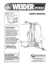
... Serial No. Write the serial number in this manual before using this manual for future reference. Serial Number Decal (Under Seat) QUESTIONS? MST CAUTION Read all precautions and instructions in the space above for future reference. ® USER'S MANUAL Visit our website at www.weiderfitness.com new products, prizes, fitness tips, and much more! As a manufacturer, we are missing parts, we will provide immediate assistance, free...
... Serial No. Write the serial number in this manual before using this manual for future reference. Serial Number Decal (Under Seat) QUESTIONS? MST CAUTION Read all precautions and instructions in the space above for future reference. ® USER'S MANUAL Visit our website at www.weiderfitness.com new products, prizes, fitness tips, and much more! As a manufacturer, we are missing parts, we will provide immediate assistance, free...
English Manual
Page 2
... authorized by sufficient proof of purchase. TABLE OF CONTENTS LIMITED WARRANTY 2 IMPORTANT PRECAUTIONS 3 BEFORE YOU BEGIN 4 ASSEMBLY 5 HOW TO USE THE TRAINING SYSTEM 21 WEIGHT RESISTANCE CHART 23 TROUBLE-SHOOTING AND MAINTENANCE 24 CABLE DIAGRAMS 25 ORDERING REPLACEMENT PARTS Back Cover Note: A PART IDENTIFICATION CHART and a PART LIST/EXPLODED DRAWING are attached in workmanship and material, under this warranty is limited to replacing or repairing, at ICON's option, the product at one of its authorized...
... authorized by sufficient proof of purchase. TABLE OF CONTENTS LIMITED WARRANTY 2 IMPORTANT PRECAUTIONS 3 BEFORE YOU BEGIN 4 ASSEMBLY 5 HOW TO USE THE TRAINING SYSTEM 21 WEIGHT RESISTANCE CHART 23 TROUBLE-SHOOTING AND MAINTENANCE 24 CABLE DIAGRAMS 25 ORDERING REPLACEMENT PARTS Back Cover Note: A PART IDENTIFICATION CHART and a PART LIST/EXPLODED DRAWING are attached in workmanship and material, under this warranty is limited to replacing or repairing, at ICON's option, the product at one of its authorized...
English Manual
Page 3
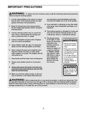
... for home use of this manual and in the locations shown on a level surface. The decals shown at any exercise program, consult your physician. Replace any commercial, rental, or institutional setting. 13. If a decal is the responsibility of the owner to the training system in the accompanying literature before using the training system. 1. Read all precautions. 2. Never release the press arm, butterfly arms, leg lever, lat bar, ab strap...
... for home use of this manual and in the locations shown on a level surface. The decals shown at any exercise program, consult your physician. Replace any commercial, rental, or institutional setting. 13. If a decal is the responsibility of the owner to the training system in the accompanying literature before using the training system. 1. Read all precautions. 2. Never release the press arm, butterfly arms, leg lever, lat bar, ab strap...
English Manual
Page 4
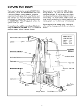
... further, please review the drawing below and familiarize yourself with the parts that are labeled. The WEIDER® 9300 PRO offers a selection of weight stations designed to the training system (see the front cover of the body. For your cardiovascular system, the WEIDER® 9300 PRO will help us assist you want. High Pulley Station Lat Bar WARNING DECAL 1 Ab Pulley Station Backrests WARNING DECAL 2 ASSEMBLED DIMENSIONS: Height...
... further, please review the drawing below and familiarize yourself with the parts that are labeled. The WEIDER® 9300 PRO offers a selection of weight stations designed to the training system (see the front cover of the body. For your cardiovascular system, the WEIDER® 9300 PRO will help us assist you want. High Pulley Station Lat Bar WARNING DECAL 1 Ab Pulley Station Backrests WARNING DECAL 2 ASSEMBLED DIMENSIONS: Height...
English Manual
Page 5
... also need grease or petroleum jelly, a small amount of its weight and size, the training system should be assembled in the location where it will be used in assembly, we have the following tools: • Two (2) adjustable wrenches • One (1) standard screwdriver • One (1) phillips screwdriver • One (1) rubber mallet • You will attach the cables and pulleys that connect the arms to Orient Parts As...
... also need grease or petroleum jelly, a small amount of its weight and size, the training system should be assembled in the location where it will be used in assembly, we have the following tools: • Two (2) adjustable wrenches • One (1) standard screwdriver • One (1) phillips screwdriver • One (1) rubber mallet • You will attach the cables and pulleys that connect the arms to Orient Parts As...
English Manual
Page 9
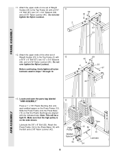
... 40 67 23 FRAME ASSEMBLY 12. Attach the upper ends of the other set of Weight Guides (23) to the Top Frame (2) with 12 a 5/16" x 6" Bolt (67), two 1/2" x 3/4" Spacers (69), and a 5/16" Nylon Locknut (40). Lubricate the 3/8" x 8" Bolt (52). Locate and open the parts bag labeled "ARM ASSEMBLY." Note: This will be a tight fit. Attach the upper ends of one set of Weight Guides (23) to the Top...
... 40 67 23 FRAME ASSEMBLY 12. Attach the upper ends of the other set of Weight Guides (23) to the Top Frame (2) with 12 a 5/16" x 6" Bolt (67), two 1/2" x 3/4" Spacers (69), and a 5/16" Nylon Locknut (40). Lubricate the 3/8" x 8" Bolt (52). Locate and open the parts bag labeled "ARM ASSEMBLY." Note: This will be a tight fit. Attach the upper ends of one set of Weight Guides (23) to the Top...

English Manual
Page 10
...the Press Arms (7). If they must be removed, you thoroughly understand the step. Slide the Left Fly Arm onto the indicated axle. Tap two 1" Retainers (45) and a 1" Round Outer Cap (46) onto the axle. 14. Repeat this step, be assembled only once. Attach the other Press Arm (not...10 Lubricate both axles on the Retainers bend toward the Round Outer Cap, as shown in this step for the other Press Arm (7) to confuse the Left Arm with two 5/16" x 2 1/2" Bolts (39) and two 5/16" Nylon Locknuts (40). Press a 1 3/4" Square Inner Cap (48) into the Press Arm. Press ...
...the Press Arms (7). If they must be removed, you thoroughly understand the step. Slide the Left Fly Arm onto the indicated axle. Tap two 1" Retainers (45) and a 1" Round Outer Cap (46) onto the axle. 14. Repeat this step, be assembled only once. Attach the other Press Arm (not...10 Lubricate both axles on the Retainers bend toward the Round Outer Cap, as shown in this step for the other Press Arm (7) to confuse the Left Arm with two 5/16" x 2 1/2" Bolts (39) and two 5/16" Nylon Locknuts (40). Press a 1 3/4" Square Inner Cap (48) into the Press Arm. Press ...
English Manual
Page 11
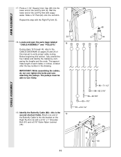
... the CABLE DIAGRAMS on the Right Fly Arm (5) with soapy water. Repeat this manual to turn freely. 19. IMPORTANT: While assembling the cables, do not over tighten the bolts and nuts attaching the pulleys. Attach one end of each Cable, in the drawing. ARM ASSEMBLY 17. Wet the lower end of the Left Fly Arm (6). Locate and open the parts bags labeled 18 "CABLE ASSEMBLY" and "PULLEYS." Before beginning this is listed after the key number...
... the CABLE DIAGRAMS on the Right Fly Arm (5) with soapy water. Repeat this manual to turn freely. 19. IMPORTANT: While assembling the cables, do not over tighten the bolts and nuts attaching the pulleys. Attach one end of each Cable, in the drawing. ARM ASSEMBLY 17. Wet the lower end of the Left Fly Arm (6). Locate and open the parts bags labeled 18 "CABLE ASSEMBLY" and "PULLEYS." Before beginning this is listed after the key number...

English Manual
Page 12
... the Press Upright (4) with a 3/8" x 2" Bolt (50) and a 3/8" Nylon Locknut (42). Attach the Pulley and a Cable Trap (80) to the the bracket on the Press Upright (4) with a 5/16" x 1" Shoulder Bolt (51) and a 5/16" Nylon Nylon Locknut (40). 51 88 40 6 12 Note: The Left Fly Arm (6) is positioned to hold the Cable in the groove of the Pulley. 80 50 42 82 88 4 CABLE ASSEMBLY...
... the Press Upright (4) with a 3/8" x 2" Bolt (50) and a 3/8" Nylon Locknut (42). Attach the Pulley and a Cable Trap (80) to the the bracket on the Press Upright (4) with a 5/16" x 1" Shoulder Bolt (51) and a 5/16" Nylon Nylon Locknut (40). 51 88 40 6 12 Note: The Left Fly Arm (6) is positioned to hold the Cable in the groove of the Pulley. 80 50 42 82 88 4 CABLE ASSEMBLY...

English Manual
Page 16
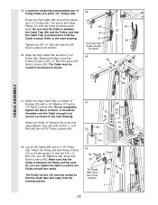
... Locknut (42). Do not completely tighten the Nylon Locknut. Wrap the High Cable (84) around a 3 1/2" Pulley (82). 35. Attach the Pulley and a Cable Trap (80) to the Top Frame (2) with a 3/8" x 3 3/4" Bolt (76), a 3/8" Washer (38), and a 3/8" Nylon Jam Nut (43). Attach the Pulley and a Cable Trap (80) to the Press Upright (4) with a 3/8" x 2" Bolt (50) and a 3/8" Nylon Locknut (42). Attach the Pulley and a Cable Trap (80) to the...
... Locknut (42). Do not completely tighten the Nylon Locknut. Wrap the High Cable (84) around a 3 1/2" Pulley (82). 35. Attach the Pulley and a Cable Trap (80) to the Top Frame (2) with a 3/8" x 3 3/4" Bolt (76), a 3/8" Washer (38), and a 3/8" Nylon Jam Nut (43). Attach the Pulley and a Cable Trap (80) to the Press Upright (4) with a 3/8" x 2" Bolt (50) and a 3/8" Nylon Locknut (42). Attach the Pulley and a Cable Trap (80) to the...
English Manual
Page 17
... 50 82 84 CABLE ASSEMBLY 41. Attach the High Cable (84) to the Ab Upright (1) with a 1/4" Washer (37) and a 1/4" Nylon Locknut (44). as shown in the direction shown. 39 84 50 31 End with a 5/16" x 1 3/4" Bolt (68) and a 5/16" Nylon Locknut (40). 42. the Pulley should be in place. Route the High Cable (84) around a 3 1/2" Pulley (82). Tighten the 3/8" x 2" Bolt (50) and the...
... 50 82 84 CABLE ASSEMBLY 41. Attach the High Cable (84) to the Ab Upright (1) with a 1/4" Washer (37) and a 1/4" Nylon Locknut (44). as shown in the direction shown. 39 84 50 31 End with a 5/16" x 1 3/4" Bolt (68) and a 5/16" Nylon Locknut (40). 42. the Pulley should be in place. Route the High Cable (84) around a 3 1/2" Pulley (82). Tighten the 3/8" x 2" Bolt (50) and the...

English Manual
Page 19
... Upright with two 1/4" x 3/4" Screws (59). the Leg Lever must pivot freely. Insert a 1/4" x 2" Carriage Bolt (61) through the indicated hole in the Ab Upright (1). Attach a 1/4" Washer (37) and a 1/4" Nylon Locknut (44) onto the Carriage Bolt. Insert the 3/8" x 2" Eyebolt (79) into the Rear Seat Frame (16). Locate and open the parts bag labeled 46 "SEAT ASSEMBLY." Press a 1 1/2" Square Inner Cap (57) into the Leg Lever (15) from the direction...
... Upright with two 1/4" x 3/4" Screws (59). the Leg Lever must pivot freely. Insert a 1/4" x 2" Carriage Bolt (61) through the indicated hole in the Ab Upright (1). Attach a 1/4" Washer (37) and a 1/4" Nylon Locknut (44) onto the Carriage Bolt. Insert the 3/8" x 2" Eyebolt (79) into the Rear Seat Frame (16). Locate and open the parts bag labeled 46 "SEAT ASSEMBLY." Press a 1 1/2" Square Inner Cap (57) into the Leg Lever (15) from the direction...
English Manual
Page 20
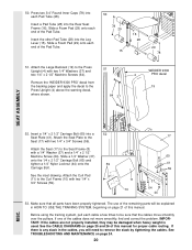
... remaining parts will be explained in the cables, you will need to remove the slack by tightening the cables. Insert a Pad Tube (28) into a Seat Plate (41). Insert a 1/4" x 2 1/2" Carriage Bolt (60) into the Rear Seat Frame (16). Attach the Seat (17) to the Seat (17) with a 1/4" Washer (37) and a 1/4" x 2 1/2" Machine Screw (64). Slide a Foam Pad (29) onto each end of this manual for proper cable routing. Remove the 'WEIDER 9300 PRO' decal...
... remaining parts will be explained in the cables, you will need to remove the slack by tightening the cables. Insert a Pad Tube (28) into a Seat Plate (41). Insert a 1/4" x 2 1/2" Carriage Bolt (60) into the Rear Seat Frame (16). Attach the Seat (17) to the Seat (17) with a 1/4" Washer (37) and a 1/4" x 2 1/2" Machine Screw (64). Slide a Foam Pad (29) onto each end of this manual for proper cable routing. Remove the 'WEIDER 9300 PRO' decal...
English Manual
Page 21
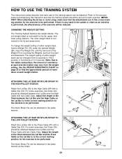
... lower pulley stations. For some exercises, the Chain (34) should be performed. CHANGING THE WEIGHT SETTING The Training System features two weight stacks. Adjust the length of the Chain between the Lat Bar and the High Cable with a Cable Clip (33). IMPORTANT: When attaching the lat bar or nylon strap, make sure that the attachments are in the correct starting position for the exercise to the fly and press arms. To change the weight setting...
... lower pulley stations. For some exercises, the Chain (34) should be performed. CHANGING THE WEIGHT SETTING The Training System features two weight stacks. Adjust the length of the Chain between the Lat Bar and the High Cable with a Cable Clip (33). IMPORTANT: When attaching the lat bar or nylon strap, make sure that the attachments are in the correct starting position for the exercise to the fly and press arms. To change the weight setting...
English Manual
Page 22
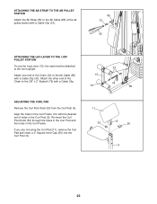
ATTACHING THE AB STRAP TO THE AB PULLEY STATION Attach the Ab Strap (35) to the Ab Cable (85) at the ab pulley station with a Cable Clip (33). 85 33 35 ATTACHING THE LEG LEVER TO THE LOW PULLEY STATION To use the Leg Lever (15), the seat must be attached to the Ab Cable (85) with a Cable Clip. 15 79 33 34 85 ADJUSTING THE CURL PAD Remove the...
ATTACHING THE AB STRAP TO THE AB PULLEY STATION Attach the Ab Strap (35) to the Ab Cable (85) at the ab pulley station with a Cable Clip (33). 85 33 35 ATTACHING THE LEG LEVER TO THE LOW PULLEY STATION To use the Leg Lever (15), the seat must be attached to the Ab Cable (85) with a Cable Clip. 15 79 33 34 85 ADJUSTING THE CURL PAD Remove the...
English Manual
Page 23
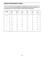
... 23 The other numbers refer to the 6.5 lb. Note: The actual resistance at each weight station may vary due to differences in individual weight plates, as well as friction between the cables, pulleys, and weight guides. weight plates. WEIGHT RESISTANCE CHART This chart shows the approximate weight resistance at each weight station. "Top" refers to the 12.5 lb. The butterfly arm resistance listed is the resistance for each butterfly arm. top weight.
... 23 The other numbers refer to the 6.5 lb. Note: The actual resistance at each weight station may vary due to differences in individual weight plates, as well as friction between the cables, pulleys, and weight guides. weight plates. WEIGHT RESISTANCE CHART This chart shows the approximate weight resistance at each weight station. "Top" refers to the 12.5 lb. The butterfly arm resistance listed is the resistance for each butterfly arm. top weight.
English Manual
Page 24
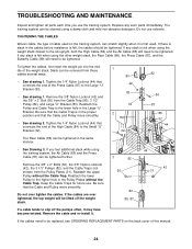
...), 3 1/2" Pulley (82), and Large "U" Bracket (83). Be sure that connects the end of the weight stack. To tighten the cables, first insert the weight pin into the middle of the Press Cable (87) to be tightened. If there is slack in the cables before resistance is first used. Do not use . TROUBLESHOOTING AND MAINTENANCE Inspect and tighten all parts each time you feel additional slack while using the training system...
...), 3 1/2" Pulley (82), and Large "U" Bracket (83). Be sure that connects the end of the weight stack. To tighten the cables, first insert the weight pin into the middle of the Press Cable (87) to be tightened. If there is slack in the cables before resistance is first used. Do not use . TROUBLESHOOTING AND MAINTENANCE Inspect and tighten all parts each time you feel additional slack while using the training system...

English Manual
Page 25
The starting and ending points of the Press Cable (87), the Ab Cable (85), the Butterfly Cable (88), the High Cable (84), and the Rear Cable (86). Press Cable (87) Ab Cable (85) 10-Large "U" Bracket 3 Ab Pulley-1 2 7 6 45 3 9 8 2 1 4-Low Pulley Butterfly Cable (88) 4 5-Left Arm 2 1-Right Arm 3 25 IMPORTANT: If the Cables have been labeled. Use the diagrams to be sure that the Cables have been assembled correctly. The numbers show the...
The starting and ending points of the Press Cable (87), the Ab Cable (85), the Butterfly Cable (88), the High Cable (84), and the Rear Cable (86). Press Cable (87) Ab Cable (85) 10-Large "U" Bracket 3 Ab Pulley-1 2 7 6 45 3 9 8 2 1 4-Low Pulley Butterfly Cable (88) 4 5-Left Arm 2 1-Right Arm 3 25 IMPORTANT: If the Cables have been labeled. Use the diagrams to be sure that the Cables have been assembled correctly. The numbers show the...
English Manual
Page 31
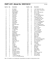
...x 2 1/4" Bolt 72 1 Nylon Strap 73 1 3/8" x 4" Bolt 74 2 Pulley Cover 75 2 Weight Pin 76 5 3/8" x 3 3/4" Bolt 77 1 5/16" x 2 3/4" Carriage Bolt 78 4 3/4" Round Inner Cap 79 1 3/8" x 2" Eyebolt 80 15 Cable Trap 81 2 "V" Pulley 82 20 3 1/2" Pulley 83 1 Large "U" Bracket 84 1 High Cable 85 1 Ab Cable 86 1 Rear Cable 87 1 Press Cable 88 1 Butterfly Cable 89 16 Weight 90 2 5/16" Nylon Jam Nut 91 1 5/16" x 3" Bolt # 1 User's Manual # 1 Exercise Guide Note: "#" indicates a non-illustrated part. PART LIST-Model No. Description Key No...
...x 2 1/4" Bolt 72 1 Nylon Strap 73 1 3/8" x 4" Bolt 74 2 Pulley Cover 75 2 Weight Pin 76 5 3/8" x 3 3/4" Bolt 77 1 5/16" x 2 3/4" Carriage Bolt 78 4 3/4" Round Inner Cap 79 1 3/8" x 2" Eyebolt 80 15 Cable Trap 81 2 "V" Pulley 82 20 3 1/2" Pulley 83 1 Large "U" Bracket 84 1 High Cable 85 1 Ab Cable 86 1 Rear Cable 87 1 Press Cable 88 1 Butterfly Cable 89 16 Weight 90 2 5/16" Nylon Jam Nut 91 1 5/16" x 3" Bolt # 1 User's Manual # 1 Exercise Guide Note: "#" indicates a non-illustrated part. PART LIST-Model No. Description Key No...
English Manual
Page 33
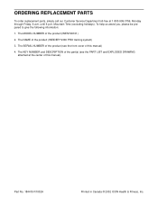
... MODEL NUMBER of the product (WEIDER® 9300 PRO training system) 3. The SERIAL NUMBER of the product (see the PART LIST and EXPLODED DRAWING attached at 1-800-999-3756, Monday through Friday, 6 a.m. The KEY NUMBER and DESCRIPTION of the part(s) (see the front cover of this manual) 4. until 6 p.m. The NAME of the product (WESY29101) 2. To help us assist you, please be prepared to give the following information: 1. Part...
... MODEL NUMBER of the product (WEIDER® 9300 PRO training system) 3. The SERIAL NUMBER of the product (see the PART LIST and EXPLODED DRAWING attached at 1-800-999-3756, Monday through Friday, 6 a.m. The KEY NUMBER and DESCRIPTION of the part(s) (see the front cover of this manual) 4. until 6 p.m. The NAME of the product (WESY29101) 2. To help us assist you, please be prepared to give the following information: 1. Part...


