
English Manual
Page 2
...FITNESS, INC., 1500 S. 1000 W., LOGAN, UT 84321-9813 2 TABLE OF CONTENTS LIMITED WARRANTY 2 IMPORTANT PRECAUTIONS 3 BEFORE YOU BEGIN 4 ASSEMBLY 5 HOW TO USE THE TRAINING SYSTEM 21 WEIGHT RESISTANCE CHART 23 TROUBLE-SHOOTING AND MAINTENANCE 24 CABLE DIAGRAMS 25 ORDERING REPLACEMENT PARTS Back Cover ... warranty is a registered trademark of whatsoever nature. Remove the PART IDENTIFICATION CHART and the PART LIST/EXPLODED DRAWING before beginning assembly. WEIDER is limited to replacing or repairing, at ICON's option, the product at one of its scope and duration to be received...
...FITNESS, INC., 1500 S. 1000 W., LOGAN, UT 84321-9813 2 TABLE OF CONTENTS LIMITED WARRANTY 2 IMPORTANT PRECAUTIONS 3 BEFORE YOU BEGIN 4 ASSEMBLY 5 HOW TO USE THE TRAINING SYSTEM 21 WEIGHT RESISTANCE CHART 23 TROUBLE-SHOOTING AND MAINTENANCE 24 CABLE DIAGRAMS 25 ORDERING REPLACEMENT PARTS Back Cover ... warranty is a registered trademark of whatsoever nature. Remove the PART IDENTIFICATION CHART and the PART LIST/EXPLODED DRAWING before beginning assembly. WEIDER is limited to replacing or repairing, at ICON's option, the product at one of its scope and duration to be received...
English Manual
Page 4
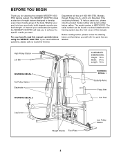
...this manual). If you , please note the product model number and serial number before using the WEIDER® 9300 PRO. For your cardiovascular system, the WEIDER® 9300 PRO will help us assist you have additional questions, please call our Customer Service Department toll-free ...at 1-800-999-3756, Monday through Friday, 6 a.m. High Pulley Station Lat Bar WARNING DECAL 1 Ab Pulley Station Backrests WARNING DECAL 2 ASSEMBLED DIMENSIONS: Height...
...this manual). If you , please note the product model number and serial number before using the WEIDER® 9300 PRO. For your cardiovascular system, the WEIDER® 9300 PRO will help us assist you have additional questions, please call our Customer Service Department toll-free ...at 1-800-999-3756, Monday through Friday, 6 a.m. High Pulley Station Lat Bar WARNING DECAL 1 Ab Pulley Station Backrests WARNING DECAL 2 ASSEMBLED DIMENSIONS: Height...
English Manual
Page 5
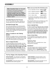
... is designed to the weights. Important: Wait until you identify the small parts used . Tightening Parts Tighten all parts as you assemble them, unless instructed to walk around the training system as shown in the center of ratchet wrenches. The Four Stages of evenings....during each stage are oriented exactly as you have included a PART IDENTIFICATION CHART in the drawings. Before beginning assembly, make the task enjoyable, assembly will be assembled successfully by deciding to make sure to the many features of the training system in the parts bag, check...
... is designed to the weights. Important: Wait until you identify the small parts used . Tightening Parts Tighten all parts as you assemble them, unless instructed to walk around the training system as shown in the center of ratchet wrenches. The Four Stages of evenings....during each stage are oriented exactly as you have included a PART IDENTIFICATION CHART in the drawings. Before beginning assembly, make the task enjoyable, assembly will be assembled successfully by deciding to make sure to the many features of the training system in the parts bag, check...

English Manual
Page 6
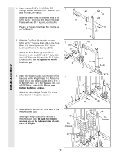
Attach the Butterfly Frame (3) to read all of the Weight Base. Locate and open the parts bags labeled "FRAME ASSEMBLY BAG ONE" and "FRAME ASSEMBLY BAG TWO." Insert two 5/16" x 2 1/2" Carriage Bolts (49) up through the Weight Base (14). Hand tighten two 5/16" Nylon Locknuts (40) onto the ... the Press Base (13). Do not tighten the Nylon Locknuts yet. 1 58 55 58 14 20 49 56 2 13 40 49 56 1 4 40 40 FRAME ASSEMBLY 3. Press two 2" Square Inner Caps (56) into the end of the information on the side shown. 1. Insert four 5/16" x 2 1/2" Carriage Bolts up through...
Attach the Butterfly Frame (3) to read all of the Weight Base. Locate and open the parts bags labeled "FRAME ASSEMBLY BAG ONE" and "FRAME ASSEMBLY BAG TWO." Insert two 5/16" x 2 1/2" Carriage Bolts (49) up through the Weight Base (14). Hand tighten two 5/16" Nylon Locknuts (40) onto the ... the Press Base (13). Do not tighten the Nylon Locknuts yet. 1 58 55 58 14 20 49 56 2 13 40 49 56 1 4 40 40 FRAME ASSEMBLY 3. Press two 2" Square Inner Caps (56) into the end of the information on the side shown. 1. Insert four 5/16" x 2 1/2" Carriage Bolts up through...
English Manual
Page 7
... indicated side of each stack of Weight Guides (23). Slide eight Weights (89) onto each of Curl Post (9). 40 8 56 20 40 55 9 20 FRAME ASSEMBLY 5. Press a 2" Square Inner Cap (56) into the Curl Post (9). 4. Attach the other Weight Guides (23) to the Press Upright (4) with two 5/16" Nylon Locknuts (40...
... indicated side of each stack of Weight Guides (23). Slide eight Weights (89) onto each of Curl Post (9). 40 8 56 20 40 55 9 20 FRAME ASSEMBLY 5. Press a 2" Square Inner Cap (56) into the Curl Post (9). 4. Attach the other Weight Guides (23) to the Press Upright (4) with two 5/16" Nylon Locknuts (40...
English Manual
Page 8
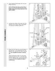
Lubricate the insides of the holes in the upper Weights. 25 26 89 89 FRAME ASSEMBLY 9. Slide a Top Weight 9 onto each stack of Weight Guides (23). Do not tighten the Nylon Locknuts yet. 1 40 40 4 8 Attach the Top Frame (2) to the ...
Lubricate the insides of the holes in the upper Weights. 25 26 89 89 FRAME ASSEMBLY 9. Slide a Top Weight 9 onto each stack of Weight Guides (23). Do not tighten the Nylon Locknuts yet. 1 40 40 4 8 Attach the Top Frame (2) to the ...
English Manual
Page 9
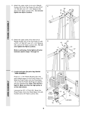
... continuing, firmly tighten all nylon locknuts used in steps 1 through 12. 40 2 69 23 67 23 13. Locate and open the parts bag labeled "ARM ASSEMBLY." Attach the Press Frame (12) to the Top Frame (2) with the Bolt and a 3/8" Nylon Locknut (42). 13 High Pulley Welded Spacers 42 9 12 52 Tube... 13 Lubricate 54 ARM ASSEMBLY Do not over tighten the Nylon Locknut. 11 2 69 40 67 23 FRAME ASSEMBLY 12. Attach the upper ends of one set of Weight Guides (23) to the Press Base (13) with a 5/16...
... continuing, firmly tighten all nylon locknuts used in steps 1 through 12. 40 2 69 23 67 23 13. Locate and open the parts bag labeled "ARM ASSEMBLY." Attach the Press Frame (12) to the Top Frame (2) with the Bolt and a 3/8" Nylon Locknut (42). 13 High Pulley Welded Spacers 42 9 12 52 Tube... 13 Lubricate 54 ARM ASSEMBLY Do not over tighten the Nylon Locknut. 11 2 69 40 67 23 FRAME ASSEMBLY 12. Attach the upper ends of one set of Weight Guides (23) to the Press Base (13) with a 5/16...

English Manual
Page 10
..., as shown in this step for the other Press Arm (7) to one of the 14 Press Frame (12) with the Right Arm (5). IMPORTANT NOTE: Before assembling the 1" Retainers (45) used in the inset drawing. Tap two 1" Retainers (45) and a 1" Round Outer Cap (46) onto the axle. Attach the other Press Arm... end of the Left Arm is behind the indicated bracket on the Butterfly Frame (3). Attach the Right Fly Arm (5) in the same manner. 39 7 ARM ASSEMBLY 15. Attach a Press Arm (7) to the Press Frame (12) in the same manner. 16 5 3 Lubricate Axle 48 Bracket 45 46 6 Axle 45 46 10 14...
..., as shown in this step for the other Press Arm (7) to one of the 14 Press Frame (12) with the Right Arm (5). IMPORTANT NOTE: Before assembling the 1" Retainers (45) used in the inset drawing. Tap two 1" Retainers (45) and a 1" Round Outer Cap (46) onto the axle. Attach the other Press Arm... end of the Left Arm is behind the indicated bracket on the Butterfly Frame (3). Attach the Right Fly Arm (5) in the same manner. 39 7 ARM ASSEMBLY 15. Attach a Press Arm (7) to the Press Frame (12) in the same manner. 16 5 3 Lubricate Axle 48 Bracket 45 46 6 Axle 45 46 10 14...
English Manual
Page 11
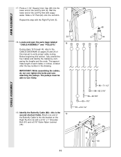
...is listed after the key number in inches, is the 19 second shortest Cable. Before beginning this step with the Right Fly Arm (5). 5 6 48 CABLE ASSEMBLY 22 18. Slide a 10" Pad (22) onto the Left Arm. The pulleys must be able to the the bracket on pages 25 and 26 of... manual to verify proper cable routing. During steps 19 through 45, refer to the CABLE DIAGRAMS on the Right Fly Arm (5) with soapy water. ARM ASSEMBLY 17. Press a 1 3/4" Square Inner Cap (48) into the 17 lower end of the Butterfly Cable to turn freely. 19. Locate and open the parts ...
...is listed after the key number in inches, is the 19 second shortest Cable. Before beginning this step with the Right Fly Arm (5). 5 6 48 CABLE ASSEMBLY 22 18. Slide a 10" Pad (22) onto the Left Arm. The pulleys must be able to the the bracket on pages 25 and 26 of... manual to verify proper cable routing. During steps 19 through 45, refer to the CABLE DIAGRAMS on the Right Fly Arm (5) with soapy water. ARM ASSEMBLY 17. Press a 1 3/4" Square Inner Cap (48) into the 17 lower end of the Butterfly Cable to turn freely. 19. Locate and open the parts ...

English Manual
Page 12
... downward. Attach the Pulley and a 22 Cable Trap (80) to hold the Cable in the groove of the Pulley. 80 50 42 82 88 4 CABLE ASSEMBLY 23. Note: The Left Fly Arm (6) is positioned to the other side of the Pulley Plates (31) with two holes 31 should be oriented as...
... downward. Attach the Pulley and a 22 Cable Trap (80) to hold the Cable in the groove of the Pulley. 80 50 42 82 88 4 CABLE ASSEMBLY 23. Note: The Left Fly Arm (6) is positioned to the other side of the Pulley Plates (31) with two holes 31 should be oriented as...

English Manual
Page 13
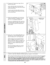
..." Nylon Locknut (40). 37 44 13 86 40 37 44 25 Thread a 5/16" Nylon Jam Nut (90) onto the Bolt. Note: This may come pre-assembled. 25 86 Route the Rear Cable (86) through the Large "U" Bracket (83) and the 3 1/2" Pulley (82). Be sure that the Cable Trap is the 24... shortest Cable. Attach the Pulley to pivot. 2 90 91 86 CABLE ASSEMBLY 25. The Cable must be threaded onto the end of the Cable only a 68 couple of the Rear Cable onto the 5/16" x 3" Bolt (91) on...
..." Nylon Locknut (40). 37 44 13 86 40 37 44 25 Thread a 5/16" Nylon Jam Nut (90) onto the Bolt. Note: This may come pre-assembled. 25 86 Route the Rear Cable (86) through the Large "U" Bracket (83) and the 3 1/2" Pulley (82). Be sure that the Cable Trap is the 24... shortest Cable. Attach the Pulley to pivot. 2 90 91 86 CABLE ASSEMBLY 25. The Cable must be threaded onto the end of the Cable only a 68 couple of the Rear Cable onto the 5/16" x 3" Bolt (91) on...

English Manual
Page 14
... that the Cable Trap is the 28 longest Cable. Tighten the 3/8" Nylon Locknut (42) and the 3/8" x 3 1/2" Bolt (not shown). 87 82 80 42 12 CABLE ASSEMBLY 14 Wrap the Press Cable around a 3 1/2" Pulley (82). Wrap the Press Cable around a "V" Pulley (81). Identify the Press Cable (87)-this is turned to the...
... that the Cable Trap is the 28 longest Cable. Tighten the 3/8" Nylon Locknut (42) and the 3/8" x 3 1/2" Bolt (not shown). 87 82 80 42 12 CABLE ASSEMBLY 14 Wrap the Press Cable around a 3 1/2" Pulley (82). Wrap the Press Cable around a "V" Pulley (81). Identify the Press Cable (87)-this is turned to the...

English Manual
Page 15
... place. 87 82 80 4 66 12 43 38 82 87 76 80 4 34. Tighten the 3/8" Nylon Locknut (not shown) and the 3/8" x 3 1/2" Bolt (66). 33. CABLE ASSEMBLY 31. Route the Press Cable (87) up around the 32 indicated 3 1/2" Pulley (82) that the Cable Trap is attached inside the Press Frame (12). Wrap...
... place. 87 82 80 4 66 12 43 38 82 87 76 80 4 34. Tighten the 3/8" Nylon Locknut (not shown) and the 3/8" x 3 1/2" Bolt (66). 33. CABLE ASSEMBLY 31. Route the Press Cable (87) up around the 32 indicated 3 1/2" Pulley (82) that the Cable Trap is attached inside the Press Frame (12). Wrap...

English Manual
Page 16
... (80) to the other bracket on the Press Base (13) closest to hold the Cable in place. 13 50 36 80 42 82 87 CABLE ASSEMBLY 37. It should be threaded onto the end of the Cable so only a couple of the Press Cable (87) to hold the Cable in place...
... (80) to the other bracket on the Press Base (13) closest to hold the Cable in place. 13 50 36 80 42 82 87 CABLE ASSEMBLY 37. It should be threaded onto the end of the Cable so only a couple of the Press Cable (87) to hold the Cable in place...
English Manual
Page 17
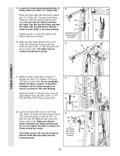
... 37 44 84 25 32 37 44 42 42 38 74; Small tabs must be down 40 42 2 84 82 80 50 82 84 CABLE ASSEMBLY 41. The end of Pulley Plates (31) and 3 1/2" Pulleys (82). Do not completely tighten the Nylon Locknut. Locate the remaining preassembled pair of the Pulley...
... 37 44 84 25 32 37 44 42 42 38 74; Small tabs must be down 40 42 2 84 82 80 50 82 84 CABLE ASSEMBLY 41. The end of Pulley Plates (31) and 3 1/2" Pulleys (82). Do not completely tighten the Nylon Locknut. Locate the remaining preassembled pair of the Pulley...

English Manual
Page 18
Be sure that the Cable and Pulley move smoothly. 1 42 85 80 82 76 31 42 50 82 80 85 CABLE ASSEMBLY 85 1 42 38 Post 82 76 18 Reattach the Pulley and the Cable Trap to hold the Cable in the Pulley Plates with the Bolt ...
Be sure that the Cable and Pulley move smoothly. 1 42 85 80 82 76 31 42 50 82 80 85 CABLE ASSEMBLY 85 1 42 38 Post 82 76 18 Reattach the Pulley and the Cable Trap to hold the Cable in the Pulley Plates with the Bolt ...

English Manual
Page 19
... (37) and a 1/4" x 2" Machine Screw (63). 48. Attach the Rear Seat Frame to the Seat (17) with two 1/4" x 3/4" Screws (59). SEAT ASSEMBLY 46. Locate and open the parts bag labeled 46 "SEAT ASSEMBLY." Attach the Seat Plate to the Ab Upright with the Bolt and a 5/16" Nylon Locknut (40). Press a 1 1/2" Square Inner Cap...
... (37) and a 1/4" x 2" Machine Screw (63). 48. Attach the Rear Seat Frame to the Seat (17) with two 1/4" x 3/4" Screws (59). SEAT ASSEMBLY 46. Locate and open the parts bag labeled 46 "SEAT ASSEMBLY." Attach the Seat Plate to the Ab Upright with the Bolt and a 5/16" Nylon Locknut (40). Press a 1 1/2" Square Inner Cap...
English Manual
Page 20
... the Pad Tube. Slide a Foam Pad (29) onto each end of the Pad Tube. 50 78 29 15 16 28 29 78 51. Remove the 'WEIDER 9300 PRO' decal from the backing paper and apply the decal to the Seat (17) with two 1/4" Washers (37) and two 1/4" x 2 1/2" Machine Screws (64). IMPORTANT: ... of this manual for proper cable routing. Attach the Seat Plate to the Press Upright (4) above the warning decal, where shown. 51 64 37 WEIDER 9300 4 PRO decal 19 SEAT ASSEMBLY 52. Attach the Seat (17) to the Press Upright (4) with two 1/4" x 3/4" Screws (59). If one of this manual. See the CABLE ...
... the Pad Tube. Slide a Foam Pad (29) onto each end of the Pad Tube. 50 78 29 15 16 28 29 78 51. Remove the 'WEIDER 9300 PRO' decal from the backing paper and apply the decal to the Seat (17) with two 1/4" Washers (37) and two 1/4" x 2 1/2" Machine Screws (64). IMPORTANT: ... of this manual for proper cable routing. Attach the Seat Plate to the Press Upright (4) above the warning decal, where shown. 51 64 37 WEIDER 9300 4 PRO decal 19 SEAT ASSEMBLY 52. Attach the Seat (17) to the Press Upright (4) with two 1/4" x 3/4" Screws (59). If one of this manual. See the CABLE ...

English Manual
Page 25
... "U" Bracket 3 Ab Pulley-1 2 7 6 45 3 9 8 2 1 4-Low Pulley Butterfly Cable (88) 4 5-Left Arm 2 1-Right Arm 3 25 Use the diagrams to be sure that the Cables have been assembled correctly.
... "U" Bracket 3 Ab Pulley-1 2 7 6 45 3 9 8 2 1 4-Low Pulley Butterfly Cable (88) 4 5-Left Arm 2 1-Right Arm 3 25 Use the diagrams to be sure that the Cables have been assembled correctly.


