
English Manual
Page 2
...shown. TABLE OF CONTENTS WARNING DECAL PLACEMENT 2 IMPORTANT PRECAUTIONS 3 BEFORE YOU BEGIN 4 PART IDENTIFICATION CHART 5 ASSEMBLY 7 ADJUSTMENTS 25 CABLE DIAGRAM 28 EXERCISE GUIDELINES 29 PART LIST 32 EXPLODED DRAWING 33 ORDERING REPLACEMENT PARTS Back Cover LIMITED WARRANTY Back Cover WARNING DECAL PLACEMENT The... decals shown here have been placed on the front cover of ICON IP, Inc. 2 WEIDER is missing or illegible, call the toll-free telephone number on the weight system. If a decal is a registered trademark of ...
...shown. TABLE OF CONTENTS WARNING DECAL PLACEMENT 2 IMPORTANT PRECAUTIONS 3 BEFORE YOU BEGIN 4 PART IDENTIFICATION CHART 5 ASSEMBLY 7 ADJUSTMENTS 25 CABLE DIAGRAM 28 EXERCISE GUIDELINES 29 PART LIST 32 EXPLODED DRAWING 33 ORDERING REPLACEMENT PARTS Back Cover LIMITED WARRANTY Back Cover WARNING DECAL PLACEMENT The... decals shown here have been placed on the front cover of ICON IP, Inc. 2 WEIDER is missing or illegible, call the toll-free telephone number on the weight system. If a decal is a registered trademark of ...
English Manual
Page 15
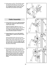
... Bolt (97), an M10 Washer, and an M10 Nylon Locknut (84). Apply grease to identify the cables and ensure proper cable routing. Attach the Cable to hold the Cable in the groove of pulleys. Make sure that the Cable Trap is oriented to the Left Butterfly Arm (22) with an M8 x 25mm Shoulder Bolt (92... 7 101 84 45 43 105 48 73 108 45 22 84 46 43 48 73 108 46 7 108 97 During steps 25-52, see the CABLE DIAGRAM on page 28 to an M10 x 75mm Bolt (96). the Leg Press Plate must be able to identify the different types of the Pulley. Identify...
... Bolt (97), an M10 Washer, and an M10 Nylon Locknut (84). Apply grease to identify the cables and ensure proper cable routing. Attach the Cable to hold the Cable in the groove of pulleys. Make sure that the Cable Trap is oriented to the Left Butterfly Arm (22) with an M8 x 25mm Shoulder Bolt (92... 7 101 84 45 43 105 48 73 108 45 22 84 46 43 48 73 108 46 7 108 97 During steps 25-52, see the CABLE DIAGRAM on page 28 to an M10 x 75mm Bolt (96). the Leg Press Plate must be able to identify the different types of the Pulley. Identify...
English Manual
Page 24
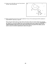
... not move smoothly over the pulleys. IMPORTANT: If the cables are not properly installed, they may be explained in the cables, you will need to the Curl Post (16) with 58 two M6 x 16mm Screws (99). 38 16 99 59. See the CABLE DIAGRAM on page 25. Attach the Curl Pad (38) to remove... the slack by tightening the cables (see page 27). 24 Make sure that the cables move smoothly, find and correct the problem. Before using the weight system, pull each...
... not move smoothly over the pulleys. IMPORTANT: If the cables are not properly installed, they may be explained in the cables, you will need to the Curl Post (16) with 58 two M6 x 16mm Screws (99). 38 16 99 59. See the CABLE DIAGRAM on page 25. Attach the Curl Pad (38) to remove... the slack by tightening the cables (see page 27). 24 Make sure that the cables move smoothly, find and correct the problem. Before using the weight system, pull each...
English Manual
Page 28
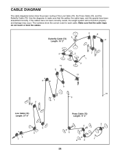
... routed, the weight system will not function properly and damage may occur. Use the diagrams to make sure that the cable traps do not touch or bind the cables. 5 Butterfly Cable (73) Length: 10' 2" 6 8 9 4 10 8 3 7 1 2 11 6 9 10 6 7 4 Low Cable (70) Length: 27' 8" 2 1 5 3 Press Cable (72) Length: 11' 2" 2 4 5 1 3 28 CABLE DIAGRAM The cable diagrams below show the correct route for each...
... routed, the weight system will not function properly and damage may occur. Use the diagrams to make sure that the cable traps do not touch or bind the cables. 5 Butterfly Cable (73) Length: 10' 2" 6 8 9 4 10 8 3 7 1 2 11 6 9 10 6 7 4 Low Cable (70) Length: 27' 8" 2 1 5 3 Press Cable (72) Length: 11' 2" 2 4 5 1 3 28 CABLE DIAGRAM The cable diagrams below show the correct route for each...


