
English Manual
Page 1
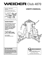
... SERVICE DEPARTMENT DIRECTLY. CALL TOLL-FREE: 1-877-992-5999 Mon.-Fri., 6 a.m.-6 p.m. Save this equipment. As a manufacturer, we are committed to providing complete customer satisfaction. Serial Number Decal (Under Seat) QUESTIONS? Visit our website at www.weiderfitness.com new products, prizes, fitness tips, and much more! MST ON THE WEB: www.weiderservice.com USER'S MANUAL CAUTION Read all precautions and instructions...
... SERVICE DEPARTMENT DIRECTLY. CALL TOLL-FREE: 1-877-992-5999 Mon.-Fri., 6 a.m.-6 p.m. Save this equipment. As a manufacturer, we are committed to providing complete customer satisfaction. Serial Number Decal (Under Seat) QUESTIONS? Visit our website at www.weiderfitness.com new products, prizes, fitness tips, and much more! MST ON THE WEB: www.weiderservice.com USER'S MANUAL CAUTION Read all precautions and instructions...
English Manual
Page 2
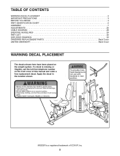
WEIDER is missing or illegible, call the toll-free telephone number on the weight system. If a decal is a registered trademark of this manual and order a free replacement decal. Apply the decal in the location shown. TABLE OF CONTENTS WARNING DECAL PLACEMENT 2 IMPORTANT PRECAUTIONS 3 BEFORE YOU BEGIN 4 PART IDENTIFICATION CHART 5 ASSEMBLY 7 ADJUSTMENTS 25 CABLE DIAGRAM 28 EXERCISE GUIDELINES 29 PART LIST 32 EXPLODED DRAWING 33 ORDERING REPLACEMENT PARTS Back Cover LIMITED WARRANTY Back Cover WARNING...
WEIDER is missing or illegible, call the toll-free telephone number on the weight system. If a decal is a registered trademark of this manual and order a free replacement decal. Apply the decal in the location shown. TABLE OF CONTENTS WARNING DECAL PLACEMENT 2 IMPORTANT PRECAUTIONS 3 BEFORE YOU BEGIN 4 PART IDENTIFICATION CHART 5 ASSEMBLY 7 ADJUSTMENTS 25 CABLE DIAGRAM 28 EXERCISE GUIDELINES 29 PART LIST 32 EXPLODED DRAWING 33 ORDERING REPLACEMENT PARTS Back Cover LIMITED WARRANTY Back Cover WARNING...
English Manual
Page 3
... the pulleys. Always disconnect the lat bar from the weight system at all instructions before using. Inspect and properly tighten all cables at any other type of weight to be used only with great force. 13. If the cables bind as described in any worn parts immediately. Keep the weight system indoors, away from moving parts. 15. Replace all parts regular- 14. Never release the arms, leg lever, lat bar, leg press, ankle strap...
... the pulleys. Always disconnect the lat bar from the weight system at all instructions before using. Inspect and properly tighten all cables at any other type of weight to be used only with great force. 13. If the cables bind as described in any worn parts immediately. Keep the weight system indoors, away from moving parts. 15. Replace all parts regular- 14. Never release the arms, leg lever, lat bar, leg press, ankle strap...
English Manual
Page 4
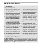
... Lat Bar Military Press Arm Adjustable Backrest Press Arm Seat Leg Press Low Pulley Station 12.5-lb. they do not correspond to a person sitting on the drawings in . / 226 cm 4 For your cardiovascular system, the weight system will help us . To help you to develop every major muscle group of this manual). To avoid a registration fee for selecting the versatile WEIDER® Club 4870 weight system. The weight...
... Lat Bar Military Press Arm Adjustable Backrest Press Arm Seat Leg Press Low Pulley Station 12.5-lb. they do not correspond to a person sitting on the drawings in . / 226 cm 4 For your cardiovascular system, the weight system will help us . To help you to develop every major muscle group of this manual). To avoid a registration fee for selecting the versatile WEIDER® Club 4870 weight system. The weight...
English Manual
Page 5
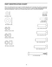
... Nylon Locknut (84) M8 x 25mm Shoulder Bolt (92) M10 x 35mm Screw (89) M10 x 40mm Bolt (104) M10 x 45mm Bolt (95) M10 x 50mm Bolt (105) 2 1/4" Bolt Set (86) 5 The number in assembly. If a part is not in the parts bag, check to identify small parts used in parentheses by each drawing is the key number of the part, from the PART LIST on page 6 to see if it has...
... Nylon Locknut (84) M8 x 25mm Shoulder Bolt (92) M10 x 35mm Screw (89) M10 x 40mm Bolt (104) M10 x 45mm Bolt (95) M10 x 50mm Bolt (105) 2 1/4" Bolt Set (86) 5 The number in assembly. If a part is not in the parts bag, check to identify small parts used in parentheses by each drawing is the key number of the part, from the PART LIST on page 6 to see if it has...
English Manual
Page 7
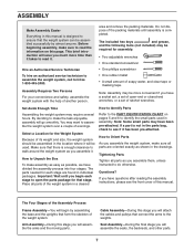
... brief introduction will assemble the arms and the moving parts. Place all parts are found in assembly. Cable Assembly-During this manual. ASSEMBLY Make Assembly Easier Everything in the location where it will be used in individual packages. Assembly Requires Two Persons For your convenience and safety, assemble the weight system with the help of this stage you have a socket set, a set of open the parts package for each stage...
... brief introduction will assemble the arms and the moving parts. Place all parts are found in assembly. Cable Assembly-During this manual. ASSEMBLY Make Assembly Easier Everything in the location where it will be used in individual packages. Assembly Requires Two Persons For your convenience and safety, assemble the weight system with the help of this stage you have a socket set, a set of open the parts package for each stage...
English Manual
Page 8
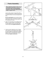
... two M10 x 80mm Carriage Bolts (88) up through the Left Base (2). Do not tighten the Bolts yet. 1 1 88 2 88 2 57 108 1 88 84 84 5 57 108 2 3. Orient the Center Upright (9) so the 2" Square 3 Inner Cap (51) is in the box on pages 5 and 6. Frame Assembly 1. For help identifying small parts, use the PART IDENTIFICATION CHART on the previous page.
... two M10 x 80mm Carriage Bolts (88) up through the Left Base (2). Do not tighten the Bolts yet. 1 1 88 2 88 2 57 108 1 88 84 84 5 57 108 2 3. Orient the Center Upright (9) so the 2" Square 3 Inner Cap (51) is in the box on pages 5 and 6. Frame Assembly 1. For help identifying small parts, use the PART IDENTIFICATION CHART on the previous page.

English Manual
Page 11
...Do not tighten the Bolts yet. Attach the Left Top Frame (4) to the Left Upright (8) with the indicated hole closer to the Center Base (5) in step 2. 89 12 7 30 30 Hole 66 84 108 68 5 108 87 11 Attach the other Weight Guide (30) to the bottom. Orient a Weight Guide (30)...Attach the Butterfly Frame (24) to the Right Top 11 Frame (3) with two M10 x 35mm Screws (89). Do not tighten the Bolts yet. Slide a Weight Bumper (66) onto the Weight Guide. Do not tighten the Screws yet. 87 3 24 84 12. Attach the Butterfly Frame (24) to the Right Upright (7) with two M10 x 65mm Bolts...
...Do not tighten the Bolts yet. Attach the Left Top Frame (4) to the Left Upright (8) with the indicated hole closer to the Center Base (5) in step 2. 89 12 7 30 30 Hole 66 84 108 68 5 108 87 11 Attach the other Weight Guide (30) to the bottom. Orient a Weight Guide (30)...Attach the Butterfly Frame (24) to the Right Top 11 Frame (3) with two M10 x 35mm Screws (89). Do not tighten the Bolts yet. Slide a Weight Bumper (66) onto the Weight Guide. Do not tighten the Screws yet. 87 3 24 84 12. Attach the Butterfly Frame (24) to the Right Upright (7) with two M10 x 65mm Bolts...
English Manual
Page 12
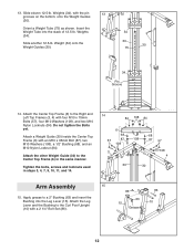
... tighten the Bolts yet. Slide another 12.5-lb. Attach the Leg Lever and the Bushing to the Center Top Frame (6) in steps 3, 4, 7, 9, 10, 11, and 14. 14 84 108 84 6 68 57 87 108 108 3 68 87 57 108 4 30 30 Arm Assembly 15 15. 13. Weight (34) onto the Weight Guides (30). 34 30 30 75 34 Pin Groove 14. Attach a Weight Guide...
... tighten the Bolts yet. Slide another 12.5-lb. Attach the Leg Lever and the Bushing to the Center Top Frame (6) in steps 3, 4, 7, 9, 10, 11, and 14. 14 84 108 84 6 68 57 87 108 108 3 68 87 57 108 4 30 30 Arm Assembly 15 15. 13. Weight (34) onto the Weight Guides (30). 34 30 30 75 34 Pin Groove 14. Attach a Weight Guide...

English Manual
Page 14
...and insert 19 the Bushing into the Press Leg (21). Do not overtighten the Nylon Locknut; cated side and attach the Leg Press to a 2 3/4" Bushing (65) and insert 22 the Bushing into the Left Base (2). Apply grease to pivot easily. Repeat this step with an M10 x 95mm Bolt (107) and an M10 Nylon ...Locknut (84). 57 27 Grease 25 27 26 2 84 12 Welded Spacer 107 65 Grease 14 Next, orient the Leg Press with the Bolt and an M10 Nylon Locknut (84). the Press Arm Handle must...
...and insert 19 the Bushing into the Press Leg (21). Do not overtighten the Nylon Locknut; cated side and attach the Leg Press to a 2 3/4" Bushing (65) and insert 22 the Bushing into the Left Base (2). Apply grease to pivot easily. Repeat this step with an M10 x 95mm Bolt (107) and an M10 Nylon ...Locknut (84). 57 27 Grease 25 27 26 2 84 12 Welded Spacer 107 65 Grease 14 Next, orient the Leg Press with the Bolt and an M10 Nylon Locknut (84). the Press Arm Handle must...
English Manual
Page 15
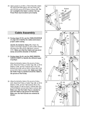
... Locknut; the Leg Press Plate must be able to identify the different types of the Pulley. During steps 24-53, see the PART IDENTIFI- 25 CATION CHART to pivot easily. Make sure that the Cable Trap is oriented to hold the Cable in the groove of the Bolt. 25. Wrap the Butterfly Cable (73) around a Pulley 26 (43). Attach the Pulley, a Cable Trap (48...
... Locknut; the Leg Press Plate must be able to identify the different types of the Pulley. During steps 24-53, see the PART IDENTIFI- 25 CATION CHART to pivot easily. Make sure that the Cable Trap is oriented to hold the Cable in the groove of the Bolt. 25. Wrap the Butterfly Cable (73) around a Pulley 26 (43). Attach the Pulley, a Cable Trap (48...
English Manual
Page 22
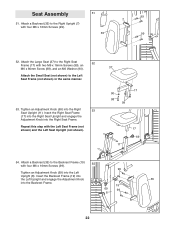
... 7 99 52. Seat Assembly 51. Attach the Small Seat (not shown) to the Right Upright (7) with two M6 x 16mm Screws (99), an M6 x 80mm Screw (98), and an M6 Washer (90). Tighten an Adjustment Knob (69) into the Right Seat Frame. Insert the Backrest Frame (19) into the Left Upright and engage the Adjustment Knob 35 into the Left Upright (8). Repeat this step with four M6...
... 7 99 52. Seat Assembly 51. Attach the Small Seat (not shown) to the Right Upright (7) with two M6 x 16mm Screws (99), an M6 x 80mm Screw (98), and an M6 Washer (90). Tighten an Adjustment Knob (69) into the Right Seat Frame. Insert the Backrest Frame (19) into the Left Upright and engage the Adjustment Knob 35 into the Left Upright (8). Repeat this step with four M6...
English Manual
Page 24
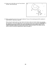
... the cables move smoothly, find and correct the problem. If one of the remaining parts will need to remove the slack by tightening the cables (see page 27). 24 IMPORTANT: If the cables are not properly installed, they may be explained in the cables, you will be damaged when heavy weight is any slack in ADJUSTMENTS, beginning on page 28 for proper cable routing. Attach the...
... the cables move smoothly, find and correct the problem. If one of the remaining parts will need to remove the slack by tightening the cables (see page 27). 24 IMPORTANT: If the cables are not properly installed, they may be explained in the cables, you will be damaged when heavy weight is any slack in ADJUSTMENTS, beginning on page 28 for proper cable routing. Attach the...
English Manual
Page 25
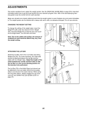
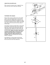
CHANGING THE WEIGHT SETTING To change the setting of resistance at the low pulley station (not shown) in the correct starting position for the exercise to see USING THE LEG LEVER LOCK on page 29 for each exercise. Adjust the length of the Chain between the Lat Bar and the Cable with two Weight Clips. Replace any worn parts immediately. Also, refer to the accompanying exercise guide to be attached to get the...
CHANGING THE WEIGHT SETTING To change the setting of resistance at the low pulley station (not shown) in the correct starting position for the exercise to see USING THE LEG LEVER LOCK on page 29 for each exercise. Adjust the length of the Chain between the Lat Bar and the Cable with two Weight Clips. Replace any worn parts immediately. Also, refer to the accompanying exercise guide to be attached to get the...
English Manual
Page 27
... cables should be removed from the indicated Pulley (43), Cable Trap (48), Half Guards (46), and Pulley Plates (49). Adjust the top Pulley (43) in the cables before resistance is oriented to the center of the weight stack. To tighten the cables, first insert the weight pin into the middle of the Pulley Plates. Reattach the Pulley, Cable Trap, B and Half Guards using the low pulley station, engage the Leg...
... cables should be removed from the indicated Pulley (43), Cable Trap (48), Half Guards (46), and Pulley Plates (49). Adjust the top Pulley (43) in the cables before resistance is oriented to the center of the weight stack. To tighten the cables, first insert the weight pin into the middle of the Pulley Plates. Reattach the Pulley, Cable Trap, B and Half Guards using the low pulley station, engage the Leg...
English Manual
Page 28
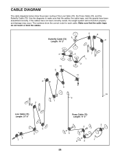
... 6 7 4 Low Cable (70) Length: 27' 8" 2 1 5 3 Press Cable (72) Length: 11' 2" 2 4 5 1 3 28 The numbers show the proper routing of the Low Cable (70), the Press Cable (72), and the Butterfly Cable (73). Make sure that the cables, the cable traps, and the guards have not been correctly routed, the weight system will not function properly and damage may occur. If the cables have been assembled correctly.
... 6 7 4 Low Cable (70) Length: 27' 8" 2 1 5 3 Press Cable (72) Length: 11' 2" 2 4 5 1 3 28 The numbers show the proper routing of the Low Cable (70), the Press Cable (72), and the Butterfly Cable (73). Make sure that the cables, the cable traps, and the guards have not been correctly routed, the weight system will not function properly and damage may occur. If the cables have been assembled correctly.
English Manual
Page 29
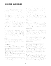
..., raising your energy level is a series of repetitions.) Determining the exact length of time for a maximum of 30 seconds between sets. Weight Loss To lose weight, use a low amount of weight and increase the number of your breath. 29 EXERCISE FORM Maintaining proper form is an efficient way to a moderate percentage of an effective exercise program. Cross Training Cross training is an essential part of their maximum capacity.
..., raising your energy level is a series of repetitions.) Determining the exact length of time for a maximum of 30 seconds between sets. Weight Loss To lose weight, use a low amount of weight and increase the number of your breath. 29 EXERCISE FORM Maintaining proper form is an efficient way to a moderate percentage of an effective exercise program. Cross Training Cross training is an essential part of their maximum capacity.

English Manual
Page 30
... workout. Sartorius (front of calf) 30 List the date, the exercises performed, the resistance used, and the numbers of thigh) I J K L M N O P Q R S T U V W X MUSCLE CHART A. A B C D E F G H I . STAYING MOTIVATED For motivation, keep a record of time after each set for a short period of each set for each stretch gradually and go only as far as you can without strain. Rest for a weight loss workout. Quadriceps (front of sets...
... workout. Sartorius (front of calf) 30 List the date, the exercises performed, the resistance used, and the numbers of thigh) I J K L M N O P Q R S T U V W X MUSCLE CHART A. A B C D E F G H I . STAYING MOTIVATED For motivation, keep a record of time after each set for a short period of each set for each stretch gradually and go only as far as you can without strain. Rest for a weight loss workout. Quadriceps (front of sets...
English Manual
Page 32
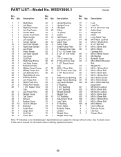
... 4 Adjustment Knob 106 1 M10 x 130mm Bolt 70 1 Low Cable 107 1 M10 x 95mm Bolt 71 2 3" Bushing 108 44 M10 Washer 72 1 Press Cable # 1 User's Manual 73 1 Butterfly Cable # 1 Exercise Guide 74 1 Lat Bar # 2 Hex Key 75 1 Weight Tube # 2 Grease Pack 76 1 Weight Tube Cap Note: "#" indicates a non-illustrated part. Description Key No. Description 1 1 Right Base 2 1 Left Base 3 1 Right Top Frame 4 1 Left Top Frame 5 1 Center Base 6 1 Center Top Frame 7 1 Right Upright 8 1 Left Upright 9 1 Center Upright...
... 4 Adjustment Knob 106 1 M10 x 130mm Bolt 70 1 Low Cable 107 1 M10 x 95mm Bolt 71 2 3" Bushing 108 44 M10 Washer 72 1 Press Cable # 1 User's Manual 73 1 Butterfly Cable # 1 Exercise Guide 74 1 Lat Bar # 2 Hex Key 75 1 Weight Tube # 2 Grease Pack 76 1 Weight Tube Cap Note: "#" indicates a non-illustrated part. Description Key No. Description 1 1 Right Base 2 1 Left Base 3 1 Right Top Frame 4 1 Left Top Frame 5 1 Center Base 6 1 Center Top Frame 7 1 Right Upright 8 1 Left Upright 9 1 Center Upright...
English Manual
Page 36
...; the NAME of the product (WEIDER CLUB 4870 weight system) • the SERIAL NUMBER of the product (see the front cover of this manual) • the KEY NUMBER and DESCRIPTION of the part(s) (see the front cover of this warranty is limited to replacing or repairing, at ICON's option, the product through one of its scope and duration to the terms set forth above is not responsible or...
...; the NAME of the product (WEIDER CLUB 4870 weight system) • the SERIAL NUMBER of the product (see the front cover of this manual) • the KEY NUMBER and DESCRIPTION of the part(s) (see the front cover of this warranty is limited to replacing or repairing, at ICON's option, the product through one of its scope and duration to the terms set forth above is not responsible or...


