

Uk Manual
Page 1
...: ICON Health & Fitness, Ltd. WEEVSY49810.0 Serial No. USERʼS MANUAL www.iconeurope.com Keep this equipment. Serial Number Decal QUESTIONS? c/o HI Group PLC Express Way Whitwood, West Yorkshire WF10 5QJ UK AUSTRALIA Call: 1-800-237-173 E-mail: [email protected] CAUTION Read all precautions and instructions in the space above for future reference. Write the serial number in this manual before using this manual for...
...: ICON Health & Fitness, Ltd. WEEVSY49810.0 Serial No. USERʼS MANUAL www.iconeurope.com Keep this equipment. Serial Number Decal QUESTIONS? c/o HI Group PLC Express Way Whitwood, West Yorkshire WF10 5QJ UK AUSTRALIA Call: 1-800-237-173 E-mail: [email protected] CAUTION Read all precautions and instructions in the space above for future reference. Write the serial number in this manual before using this manual for...
Uk Manual
Page 2
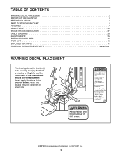
... trademark of ICON IP, Inc. 2 Note: The decal(s) may not be shown at actual size. TABLE OF CONTENTS WARNING DECAL PLACEMENT 2 IMPORTANT PRECAUTIONS 3 BEFORE YOU BEGIN 4 PART IDENTIFICATION CHART 5 ASSEMBLY 7 ADJUSTMENT 34 WEIGHT RESISTANCE CHART 37 CABLE DIAGRAM 38 MAINTENANCE 39 EXERCISE GUIDELINES 40 PART LIST 43 EXPLODED DRAWING 45 ORDERING REPLACEMENT PARTS Back Cover WARNING DECAL PLACEMENT This drawing shows the location(s) of this manual and request a free replacement decal. WEIDER is...
... trademark of ICON IP, Inc. 2 Note: The decal(s) may not be shown at actual size. TABLE OF CONTENTS WARNING DECAL PLACEMENT 2 IMPORTANT PRECAUTIONS 3 BEFORE YOU BEGIN 4 PART IDENTIFICATION CHART 5 ASSEMBLY 7 ADJUSTMENT 34 WEIGHT RESISTANCE CHART 37 CABLE DIAGRAM 38 MAINTENANCE 39 EXERCISE GUIDELINES 40 PART LIST 43 EXPLODED DRAWING 45 ORDERING REPLACEMENT PARTS Back Cover WARNING DECAL PLACEMENT This drawing shows the location(s) of this manual and request a free replacement decal. WEIDER is...
Uk Manual
Page 3
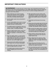
... home use of this product. 1. Do not put the weight system in serious injury or death. Inspect and properly tighten all warnings on page 36). 13. Always secure the weight stack with great force. 16. Never release the arms, leg lever, lat bar, handle, ankle strap, or double strap while weights are exercising, stop immediately and cool down. 3 The weights will fall with the lock pin...
... home use of this product. 1. Do not put the weight system in serious injury or death. Inspect and properly tighten all warnings on page 36). 13. Always secure the weight stack with great force. 16. Never release the arms, leg lever, lat bar, handle, ankle strap, or double strap while weights are exercising, stop immediately and cool down. 3 The weights will fall with the lock pin...
Uk Manual
Page 4
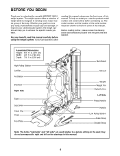
... serial number decal are used relative to tone your body, build dramatic muscle size and strength, or improve your benefit, read this manual. they do not correspond to right and left side" are shown on the drawings in . (216 cm) High Pulley Station Lat Bar Ab Station Backrest Right Side Seat Leg Lever Cable Clip Chain Foot Plate Burn Band Shroud Weight Weight Pin Butterfly Arm...
... serial number decal are used relative to tone your body, build dramatic muscle size and strength, or improve your benefit, read this manual. they do not correspond to right and left side" are shown on the drawings in . (216 cm) High Pulley Station Lat Bar Ab Station Backrest Right Side Seat Leg Lever Cable Clip Chain Foot Plate Burn Band Shroud Weight Weight Pin Butterfly Arm...

Uk Manual
Page 5
...: If you cannot find a part in assembly. PART IDENTIFICATION CHART Refer to the drawings below to identify small parts used in the hardware kit, check to see if it has been preassembled. To avoid damaging parts, do not use power tools for assembly. The number in parentheses by each drawing is the key number of the part, from the PART LIST near the end of this manual.
...: If you cannot find a part in assembly. PART IDENTIFICATION CHART Refer to the drawings below to identify small parts used in the hardware kit, check to see if it has been preassembled. To avoid damaging parts, do not use power tools for assembly. The number in parentheses by each drawing is the key number of the part, from the PART LIST near the end of this manual.
Uk Manual
Page 7
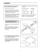
... help identifying small parts, use the PART IDENTIFICATION CHART on pages 5 and 6. • The following information and instructions: • Assembly requires two persons. • Because of its weight and size, assemble the weight system in the location where it will be more convenient if you have a socket set, a set of open-end or closed-end wrenches, or a set of ratchet wrenches. 1. ASSEMBLY To make assembly easier, read the...
... help identifying small parts, use the PART IDENTIFICATION CHART on pages 5 and 6. • The following information and instructions: • Assembly requires two persons. • Because of its weight and size, assemble the weight system in the location where it will be more convenient if you have a socket set, a set of open-end or closed-end wrenches, or a set of ratchet wrenches. 1. ASSEMBLY To make assembly easier, read the...
Uk Manual
Page 10
... Burn Pulleys (68), the three V-pulleys (not shown), and the twenty Pulleys (not shown). Route the threaded end of the Bolt Set is in the location shown. Apply some of the included grease to the Leg (10) with an M10 x 63mm Bolt (89), two 12.7mm Spacers (73), and an M10 Locknut (74). 7. Attach a second Burn Pulley (68) over the Burn Cable (45...
... Burn Pulleys (68), the three V-pulleys (not shown), and the twenty Pulleys (not shown). Route the threaded end of the Bolt Set is in the location shown. Apply some of the included grease to the Leg (10) with an M10 x 63mm Bolt (89), two 12.7mm Spacers (73), and an M10 Locknut (74). 7. Attach a second Burn Pulley (68) over the Burn Cable (45...
Uk Manual
Page 18
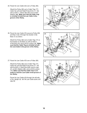
... Upright (5). Route the Low Cable (43) around a Pulley (69) and then route it through the left side of the Pulley. 69 83 71 43 88 18 17 26. Route the Low Cable (43) over a Pulley (69). 25 Attach the Pulley (69) and a Cable Trap (71) inside the Left and Right Press Arms (17, 18) with the M10 x 125mm Bolt (83) used in the groove of the Pulley...
... Upright (5). Route the Low Cable (43) around a Pulley (69) and then route it through the left side of the Pulley. 69 83 71 43 88 18 17 26. Route the Low Cable (43) over a Pulley (69). 25 Attach the Pulley (69) and a Cable Trap (71) inside the Left and Right Press Arms (17, 18) with the M10 x 125mm Bolt (83) used in the groove of the Pulley...

Uk Manual
Page 19
... an M10 Locknut (74). Route the High Cable (44) under a V-pulley 30 (67). Attach the Pulley (69) inside the Top Frame (6) with an M10 x 57mm Bolt (93) and an M10 Locknut (74). Route the High Cable through the bracket on the Top Frame (6) 28 and over a Pulley (69). 29 Attach the Pulley (69) and a Cable Trap (71) to the Upright (5) with an M10...
... an M10 Locknut (74). Route the High Cable (44) under a V-pulley 30 (67). Attach the Pulley (69) inside the Top Frame (6) with an M10 x 57mm Bolt (93) and an M10 Locknut (74). Route the High Cable through the bracket on the Top Frame (6) 28 and over a Pulley (69). 29 Attach the Pulley (69) and a Cable Trap (71) to the Upright (5) with an M10...

Uk Manual
Page 21
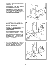
...) will be installed in the Top Frame (6) in the indicated location. Make sure that the Cable Trap is not shown in the side of the V-pulley. Route the High Cable (44) through the Top Frame as possible. Route the High Cable (44) under a V-pulley (67). 34 Attach the V-pulley (67) and a Cable Trap (71) to leave slack in the High Cable in step 61...
...) will be installed in the Top Frame (6) in the indicated location. Make sure that the Cable Trap is not shown in the side of the V-pulley. Route the High Cable (44) through the Top Frame as possible. Route the High Cable (44) under a V-pulley (67). 34 Attach the V-pulley (67) and a Cable Trap (71) to leave slack in the High Cable in step 61...

Uk Manual
Page 33
.... See MAINTENANCE on page 38 for proper cable routing. If one of the remaining parts will need to remove the slack by tightening the cables. Attach the hook on page 34. IMPORTANT: If the cables are not properly installed, they may be damaged when heavy weight is any slack in the cables, you will be explained in the location shown. 61 Attach the Pulley (69) inside...
.... See MAINTENANCE on page 38 for proper cable routing. If one of the remaining parts will need to remove the slack by tightening the cables. Attach the hook on page 34. IMPORTANT: If the cables are not properly installed, they may be damaged when heavy weight is any slack in the cables, you will be explained in the location shown. 61 Attach the Pulley (69) inside...

Uk Manual
Page 34
... Frame (not shown). Turn the bent end downward. ADJUSTING THE SEAT, THE BACKREST, AND THE LEG LOCK FRAME To adjust the Seat (24), remove the Adjustment Knob (29), move the Seat to get the most benefit from the weight setting. Insert the Weight Pin so that the Adjustment Knob is used. Make sure that all parts are properly tightened each exercise station may vary from your exercise program. Replace any worn parts immediately. Make sure...
... Frame (not shown). Turn the bent end downward. ADJUSTING THE SEAT, THE BACKREST, AND THE LEG LOCK FRAME To adjust the Seat (24), remove the Adjustment Knob (29), move the Seat to get the most benefit from the weight setting. Insert the Weight Pin so that the Adjustment Knob is used. Make sure that all parts are properly tightened each exercise station may vary from your exercise program. Replace any worn parts immediately. Make sure...

Uk Manual
Page 35
... the WEIGHT RESISTANCE CHART on page 37 to view the amount resistance added by the burn band at the ab station or the low pulley station in use, attach the hook to the Low Anchor (D) on the Burn Band. Adjust the length of the Chain between the Lat Bar (47) and the High Cable (44) with a Cable Clip (50). For some exercises, attach the...
... the WEIGHT RESISTANCE CHART on page 37 to view the amount resistance added by the burn band at the ab station or the low pulley station in use, attach the hook to the Low Anchor (D) on the Burn Band. Adjust the length of the Chain between the Lat Bar (47) and the High Cable (44) with a Cable Clip (50). For some exercises, attach the...

Uk Manual
Page 37
... 212 / 241 222 / 269 238 / 273 244 / 295 260 / 309 PRESS ARM (lbs.) 85 / 107 98 / 117 108 / 131 120 / 145 135 / 158 143 / 163 158 / 182 166 / 189 180 / 194 189 / 212 199 / 226 210 / 237 Note: 1 lb. = 0.45 kg 37 weights. The numbers in individual weights as well as friction between the cables, pulleys, and weight guides.
... 212 / 241 222 / 269 238 / 273 244 / 295 260 / 309 PRESS ARM (lbs.) 85 / 107 98 / 117 108 / 131 120 / 145 135 / 158 143 / 163 158 / 182 166 / 189 180 / 194 189 / 212 199 / 226 210 / 237 Note: 1 lb. = 0.45 kg 37 weights. The numbers in individual weights as well as friction between the cables, pulleys, and weight guides.
Uk Manual
Page 39
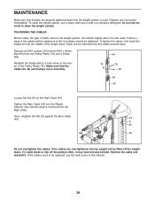
... properly tightened each time the weight system is removed from two Pulley Plates (70) and a Pulley (69). TIGHTENING THE CABLES Woven cable, the type of the Pulley Plates (70). If there is slack in the cables before resistance is first used on the High Cable (44). If the cables need to slip off the weight stack. If a cable tends to be lifted off the pulleys often, it . Replace any worn parts...
... properly tightened each time the weight system is removed from two Pulley Plates (70) and a Pulley (69). TIGHTENING THE CABLES Woven cable, the type of the Pulley Plates (70). If there is slack in the cables before resistance is first used on the High Cable (44). If the cables need to slip off the weight stack. If a cable tends to be lifted off the pulleys often, it . Replace any worn parts...
Uk Manual
Page 40
... sets performed. Adjust the intensity level of an individual exercise as one sit-up increases your bodyʼs signals. Begin with 5 to your body temperature, heart rate, and circulation in preparation for every major muscle group, emphasizing areas that is a series of repetitions. Select exercises for exercise. Weight Loss-To lose weight, use a low amount of resistance and increase the number of repetitions in each workout. Use...
... sets performed. Adjust the intensity level of an individual exercise as one sit-up increases your bodyʼs signals. Begin with 5 to your body temperature, heart rate, and circulation in preparation for every major muscle group, emphasizing areas that is a series of repetitions. Select exercises for exercise. Weight Loss-To lose weight, use a low amount of resistance and increase the number of repetitions in each workout. Use...

Uk Manual
Page 41
... Exercise 6. 7. 8. 9. 10. EXERCISE LOG Make copies of your strength and aerobic workouts. Exercise Lbs. Exercise Lbs. Lbs. Strength Date: Exercise 1. Lbs. Sets Reps Exercise 6. 7. 8. 9. 10. Sets Reps Time Distance Speed 41 Aerobic Date: Exercise Time Distance Speed Strength Date: Aerobic Date: Exercise 1. 2. 3. 4. 5. Lbs. Sets Reps Time Distance Speed Strength Date: Aerobic Date: Exercise 1. 2. 3. 4. 5. Scheduling and recording your workouts will help you to make exercise a regular and enjoyable part of this page, and use...
... Exercise 6. 7. 8. 9. 10. EXERCISE LOG Make copies of your strength and aerobic workouts. Exercise Lbs. Exercise Lbs. Lbs. Strength Date: Exercise 1. Lbs. Sets Reps Exercise 6. 7. 8. 9. 10. Sets Reps Time Distance Speed 41 Aerobic Date: Exercise Time Distance Speed Strength Date: Aerobic Date: Exercise 1. 2. 3. 4. 5. Lbs. Sets Reps Time Distance Speed Strength Date: Aerobic Date: Exercise 1. 2. 3. 4. 5. Scheduling and recording your workouts will help you to make exercise a regular and enjoyable part of this page, and use...
Uk Manual
Page 43
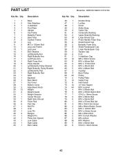
... Bolt Leg Lock Frame Leg Lever Burn Bracket Left Butterfly Arm Right Butterfly Arm Left Press Arm Right Press Arm Press Handle Left Butterfly Pulley Bracket Right Butterfly Pulley Bracket Left Butterfly Pad Right Butterfly Pad Seat Backrest Burn Band Top Cover Bottom Cover Adjustment Knob Weight Weight Guide Weight Selector Center Shroud Right Side Shroud Foam Pad Pad Cap Roll Pin Lock Lock Pin Bumper Weight Pin Press Arm Spacer Low Cable High Cable Burn Cable Model No. WEEVSY49810.0 R1210A Key...
... Bolt Leg Lock Frame Leg Lever Burn Bracket Left Butterfly Arm Right Butterfly Arm Left Press Arm Right Press Arm Press Handle Left Butterfly Pulley Bracket Right Butterfly Pulley Bracket Left Butterfly Pad Right Butterfly Pad Seat Backrest Burn Band Top Cover Bottom Cover Adjustment Knob Weight Weight Guide Weight Selector Center Shroud Right Side Shroud Foam Pad Pad Cap Roll Pin Lock Lock Pin Bumper Weight Pin Press Arm Spacer Low Cable High Cable Burn Cable Model No. WEEVSY49810.0 R1210A Key...
Uk Manual
Page 44
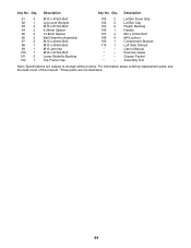
Qty. Description Key No. For information about ordering replacement parts, see the back cover of this manual. *These parts are subject to change without notice. Qty. Lat Bar Foam Grip Lat Bar Cap Plastic Bushing Handle M4 x 12mm Bolt M4 Locknut Containment Bracket Left Side Shroud Userʼs Manual Exercise Guide Grease Packet Assembly Tool Note: Specifications are not illustrated. 44 Description 91 3 92 1 93 2 94 2 95 2 96 2 97 2 98 1 99...
Qty. Description Key No. For information about ordering replacement parts, see the back cover of this manual. *These parts are subject to change without notice. Qty. Lat Bar Foam Grip Lat Bar Cap Plastic Bushing Handle M4 x 12mm Bolt M4 Locknut Containment Bracket Left Side Shroud Userʼs Manual Exercise Guide Grease Packet Assembly Tool Note: Specifications are not illustrated. 44 Description 91 3 92 1 93 2 94 2 95 2 96 2 97 2 98 1 99...
Uk Manual
Page 48
ORDERING REPLACEMENT PARTS To order replacement parts, please see the PART LIST and the EXPLODED DRAWING near the end of this manual) Part No. 306353 R1210A Printed in China © 2010 ICON IP, Inc. To help us assist you, be prepared to provide the following information when contacting us: • the model number and serial number of the product (see the front cover of this manual) • the name of the product (see the front cover of this manual) • the key number and description of the replacement part(s) (see the front cover of this manual.
ORDERING REPLACEMENT PARTS To order replacement parts, please see the PART LIST and the EXPLODED DRAWING near the end of this manual) Part No. 306353 R1210A Printed in China © 2010 ICON IP, Inc. To help us assist you, be prepared to provide the following information when contacting us: • the model number and serial number of the product (see the front cover of this manual) • the name of the product (see the front cover of this manual) • the key number and description of the replacement part(s) (see the front cover of this manual.


