
Uk Manual
Page 1
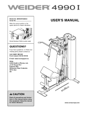
Write the serial number in this manual before using this manual for future reference. Model No. If you have questions, or if there are missing parts, please contact us: Call: 08457 089 009 From Ireland: 053 92 36102 E-mail: www.iconsupport.eu Write: ICON Health & Fitness, Ltd. c/o HI Group PLC Express Way Whitwood, West Yorkshire WF10 5QJ UK USERʼS MANUAL CAUTION Read all precautions and instructions in the space above for future reference. www.iconeurope.com Keep this equipment. WEEVSY2909.0 Serial No. Serial Number Decal (under seat) QUESTIONS?
Write the serial number in this manual before using this manual for future reference. Model No. If you have questions, or if there are missing parts, please contact us: Call: 08457 089 009 From Ireland: 053 92 36102 E-mail: www.iconsupport.eu Write: ICON Health & Fitness, Ltd. c/o HI Group PLC Express Way Whitwood, West Yorkshire WF10 5QJ UK USERʼS MANUAL CAUTION Read all precautions and instructions in the space above for future reference. www.iconeurope.com Keep this equipment. WEEVSY2909.0 Serial No. Serial Number Decal (under seat) QUESTIONS?
Uk Manual
Page 2
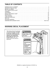
... 2 IMPORTANT PRECAUTIONS 3 BEFORE YOU BEGIN 4 PART IDENTIFICATION CHART 5 ASSEMBLY 6 ADJUSTMENT 23 WEIGHT RESISTANCE CHART 25 MAINTENANCE 26 CABLE DIAGRAM 27 EXERCISE GUIDELINES 28 PART LIST 29 EXPLODED DRAWING 30 ORDERING REPLACEMENT PARTS Back Cover WARNING DECAL PLACEMENT This drawing shows the location(s) of ICON IP, Inc. 2 Apply the decal in the location shown. WEIDER is missing or illegible, see the front cover of this manual and request a free replacement decal. If a decal is a registered...
... 2 IMPORTANT PRECAUTIONS 3 BEFORE YOU BEGIN 4 PART IDENTIFICATION CHART 5 ASSEMBLY 6 ADJUSTMENT 23 WEIGHT RESISTANCE CHART 25 MAINTENANCE 26 CABLE DIAGRAM 27 EXERCISE GUIDELINES 28 PART LIST 29 EXPLODED DRAWING 30 ORDERING REPLACEMENT PARTS Back Cover WARNING DECAL PLACEMENT This drawing shows the location(s) of ICON IP, Inc. 2 Apply the decal in the location shown. WEIDER is missing or illegible, see the front cover of this manual and request a free replacement decal. If a decal is a registered...
Uk Manual
Page 3
ICON assumes no responsibility for home use of this manual. 3 Cover the floor beneath the weight system to ensure that all users of the weight system are on the pulleys at all precautions. 3. The weights will fall with pre-existing health problems. 2. Always disconnect the lat bar and the rower bar from the weight system when performing an exercise that could become caught on the foot plate while...
ICON assumes no responsibility for home use of this manual. 3 Cover the floor beneath the weight system to ensure that all users of the weight system are on the pulleys at all precautions. 3. The weights will fall with pre-existing health problems. 2. Always disconnect the lat bar and the rower bar from the weight system when performing an exercise that could become caught on the foot plate while...
Uk Manual
Page 4
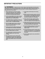
... Knob Arm Lat Bar Right Side Curl Pad Leg Lever Low Pulley Station Ab Pulley Station Ab Handle Shroud Backrest Weight Pin Left Side Seat Chain Rower Bar Foot Plate Note: The terms "right side" and "left side" are determined relative to achieve the specific results you want. For your weight system. The model number and the location of the serial number decal are labeled. Lat Bar Rest High Pulley Station ASSEMBLED DIMENSIONS...
... Knob Arm Lat Bar Right Side Curl Pad Leg Lever Low Pulley Station Ab Pulley Station Ab Handle Shroud Backrest Weight Pin Left Side Seat Chain Rower Bar Foot Plate Note: The terms "right side" and "left side" are determined relative to achieve the specific results you want. For your weight system. The model number and the location of the serial number decal are labeled. Lat Bar Rest High Pulley Station ASSEMBLED DIMENSIONS...
Uk Manual
Page 5
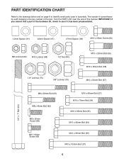
...If you cannot find a part in the hardware kit, check to identify small parts used in parentheses by each drawing is the key number of the part, from the PART LIST near the end of this manual. The number in assembly. PART IDENTIFICATION CHART Refer to the drawings below ...and on page 6 to see if it has been preassembled. 12mm Spacer (91) 22mm Spacer (97) 27mm Spacer (96) M10 x 25mm Screw...
...If you cannot find a part in the hardware kit, check to identify small parts used in parentheses by each drawing is the key number of the part, from the PART LIST near the end of this manual. The number in assembly. PART IDENTIFICATION CHART Refer to the drawings below ...and on page 6 to see if it has been preassembled. 12mm Spacer (91) 22mm Spacer (97) 27mm Spacer (96) M10 x 25mm Screw...
Uk Manual
Page 6
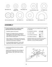
...ASSEMBLY To make assembly easier, carefully read the following information and instructions: • The following tools (not included) may be more convenient if you have a socket set, a set of open-end or closed-end wrenches, or a set of ratchet wrenches. • For help identifying small parts, use the PART IDENTIFICATION CHART on pages 5 and 6. 1. Attach the Short Base (6) to walk around the weight... as shown. two adjustable wrenches one rubber mallet one standard screwdriver one Phillips screwdriver • Place all parts in the location where it will be used. Make sure that ...
...ASSEMBLY To make assembly easier, carefully read the following information and instructions: • The following tools (not included) may be more convenient if you have a socket set, a set of open-end or closed-end wrenches, or a set of ratchet wrenches. • For help identifying small parts, use the PART IDENTIFICATION CHART on pages 5 and 6. 1. Attach the Short Base (6) to walk around the weight... as shown. two adjustable wrenches one rubber mallet one standard screwdriver one Phillips screwdriver • Place all parts in the location where it will be used. Make sure that ...
Uk Manual
Page 10
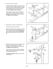
... the indicated bracket on the Leg (21) into the Seat Frame (2). Apply grease to the Upright (5) with the M10 x 75mm Bolt (94), two M10 Washers (73), and an M10 Locknut (68). Attach the Leg Lever (3) to the Seat Frame with two M10 x 25mm Screws (60) and two M10 Washers (73). See steps 5 through 9. Attach the Leg to the Leg (21) with two M10...
... the indicated bracket on the Leg (21) into the Seat Frame (2). Apply grease to the Upright (5) with the M10 x 75mm Bolt (94), two M10 Washers (73), and an M10 Locknut (68). Attach the Leg Lever (3) to the Seat Frame with two M10 x 25mm Screws (60) and two M10 Washers (73). See steps 5 through 9. Attach the Leg to the Leg (21) with two M10...
Uk Manual
Page 13
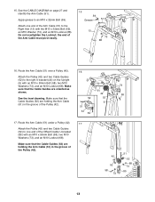
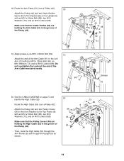
...Route the Arm Cable (51) under a Pulley (42). 17 Attach the Pulley (42) and two Cable Guides (52) to the Right Arm (13) with an M10 x 50mm Bolt (58), two M10 Washers (73), and an M10 Locknut (68). Do not overtighten the Locknut; Route the Arm Cable (51) over a Pulley (42). Make sure that the Cable Guides (52) are holding the Arm Cable... grease to the right U-bracket (22) on page 27 and identify the Arm Cable (51). See the CABLE DIAGRAM on the Upright (5) with the M10 x 32mm Bolt (59), an M10 Washer (73), and an M10 Locknut (68). Attach the Pulley (42) and two Cable Guides ...
...Route the Arm Cable (51) under a Pulley (42). 17 Attach the Pulley (42) and two Cable Guides (52) to the Right Arm (13) with an M10 x 50mm Bolt (58), two M10 Washers (73), and an M10 Locknut (68). Do not overtighten the Locknut; Route the Arm Cable (51) over a Pulley (42). Make sure that the Cable Guides (52) are holding the Arm Cable... grease to the right U-bracket (22) on page 27 and identify the Arm Cable (51). See the CABLE DIAGRAM on the Upright (5) with the M10 x 32mm Bolt (59), an M10 Washer (73), and an M10 Locknut (68). Attach the Pulley (42) and two Cable Guides ...
Uk Manual
Page 14
... Bolt (59). 19 Attach the end of the Arm Cable must pivot easily. 68 73 51 Grease 59 12 20. Make sure that the Cable Guides (52) are holding the Arm Cable (51) in the groove of the Pulley (42). 58 73 52 5 22 73 68 52 42 51 19. Route the Arm Cable (51) over a Pulley (42). See the CABLE DIAGRAM... and an M10 Locknut (68). Then, route the High Cable (53) through the Arm Frame (9) and through the Upright (5) as shown. 20 68 73 36 42 53 73 58 8 5 9 36 14 Attach the Pulley (42) and two Pulley Covers (36) to the Left Arm (12) with an M10 x 50mm Bolt (58), two M10 Washers (73), and...
... Bolt (59). 19 Attach the end of the Arm Cable must pivot easily. 68 73 51 Grease 59 12 20. Make sure that the Cable Guides (52) are holding the Arm Cable (51) in the groove of the Pulley (42). 58 73 52 5 22 73 68 52 42 51 19. Route the Arm Cable (51) over a Pulley (42). See the CABLE DIAGRAM... and an M10 Locknut (68). Then, route the High Cable (53) through the Arm Frame (9) and through the Upright (5) as shown. 20 68 73 36 42 53 73 58 8 5 9 36 14 Attach the Pulley (42) and two Pulley Covers (36) to the Left Arm (12) with an M10 x 50mm Bolt (58), two M10 Washers (73), and...

Uk Manual
Page 15
... of the way into the Weight Selector (7). Then, pull the High Cable (53) downward between the center and rear brackets on the Top Frame (8). Tighten the High Cable (53) three quarters of the Pulley (42). 21. Route the High Cable (53) through the rear 22 bracket on the Top Frame (8) with an M10 x 52mm Bolt (67), two M10 Washers (73...
... of the way into the Weight Selector (7). Then, pull the High Cable (53) downward between the center and rear brackets on the Top Frame (8). Tighten the High Cable (53) three quarters of the Pulley (42). 21. Route the High Cable (53) through the rear 22 bracket on the Top Frame (8) with an M10 x 52mm Bolt (67), two M10 Washers (73...

Uk Manual
Page 16
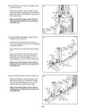
...used in the two Pulley Plates (23) with an M10 x 85mm Bolt (95), two M10 Washers (73), two 22mm Spacers (97), and an M10 Locknut (68). Hold a Pulley (42) on page 27 and identify the Ab Cable (93). 25 Route the Ab Cable (93) through the Upright (5) as shown. Next, route the Ab Cable (93) over a Pulley (42). 26 Attach the Pulley...of the Pulley (42). Attach the Pulley (42) and two Cable Guides (52) between the 24 center and rear brackets on the Top Frame (8). Route the Ab Cable (93) over a Pulley (42). Locate the High Cable (53) hanging between the highest holes in step 30. ...
...used in the two Pulley Plates (23) with an M10 x 85mm Bolt (95), two M10 Washers (73), two 22mm Spacers (97), and an M10 Locknut (68). Hold a Pulley (42) on page 27 and identify the Ab Cable (93). 25 Route the Ab Cable (93) through the Upright (5) as shown. Next, route the Ab Cable (93) over a Pulley (42). 26 Attach the Pulley...of the Pulley (42). Attach the Pulley (42) and two Cable Guides (52) between the 24 center and rear brackets on the Top Frame (8). Route the Ab Cable (93) over a Pulley (42). Locate the High Cable (53) hanging between the highest holes in step 30. ...
Uk Manual
Page 18
...Cable (54) under a Pulley (42). Make sure that the Pulley Covers (36) are holding the Low Cable (54) in the 30 indicated location. Make sure that the Cable Guides (52) are holding the Ab Cable (93) in the groove of the Pulley (42). 31 3 68 73 91 36 42 54 36 5 21 73 91 37 32. Attach the Pulley (42) and two Pulley Covers...route the Low Cable (54) under a Pulley (42). Route the Low Cable (54) through the Leg Lever (3), through the Leg (21), and through the Upright (5) as shown. Attach the Pulley (42) and two Pulley Covers (36) inside the Leg (21) with an M10 x 50mm Bolt...
...Cable (54) under a Pulley (42). Make sure that the Pulley Covers (36) are holding the Low Cable (54) in the 30 indicated location. Make sure that the Cable Guides (52) are holding the Ab Cable (93) in the groove of the Pulley (42). 31 3 68 73 91 36 42 54 36 5 21 73 91 37 32. Attach the Pulley (42) and two Pulley Covers...route the Low Cable (54) under a Pulley (42). Route the Low Cable (54) through the Leg Lever (3), through the Leg (21), and through the Upright (5) as shown. Attach the Pulley (42) and two Pulley Covers (36) inside the Leg (21) with an M10 x 50mm Bolt...
Uk Manual
Page 22
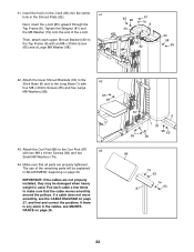
... J-bolt. Then, attach each cable a few times to the Top Frame (8) with four M8 x 20mm Screws (65) and four Large M8 Washers (98). 42 65 98 43. If a cable does not move smoothly, see MAINTENANCE on page 27, and find and correct the problem. Pull each upper Shroud Bracket (30) to make sure that all parts are not properly installed...
... J-bolt. Then, attach each cable a few times to the Top Frame (8) with four M8 x 20mm Screws (65) and four Large M8 Washers (98). 42 65 98 43. If a cable does not move smoothly, see MAINTENANCE on page 27, and find and correct the problem. Pull each upper Shroud Bracket (30) to make sure that all parts are not properly installed...
Uk Manual
Page 23
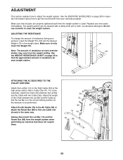
Replace any worn parts immediately. The weight system can be performed. Use the WEIGHT RESISTANCE CHART on page 28 for the exercise to be cleaned with two Cable Clips. For some exercises, attach the Chain (92) between the Lat Bar and the Cable so that all parts are properly tightened each exercise station may vary from the weight setting. ADJUSTING THE RESISTANCE To change the amount of resistance at the high pulley station with a Cable Clip...
Replace any worn parts immediately. The weight system can be performed. Use the WEIGHT RESISTANCE CHART on page 28 for the exercise to be cleaned with two Cable Clips. For some exercises, attach the Chain (92) between the Lat Bar and the Cable so that all parts are properly tightened each exercise station may vary from the weight setting. ADJUSTING THE RESISTANCE To change the amount of resistance at the high pulley station with a Cable Clip...
Uk Manual
Page 24
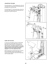
... engaged in one of the groove in the Arm Frame (9) and tighten the Lock Knob (45). Store the Curl Pad away from the weight system. 86 87 21 88 24 To use the Arms (12, 13) as butterfly arms, pivot the Lock Rod (46) into the Leg (21). Then, move the Curl Post upward or downward slightly to the... THE ARMS To use the Curl Pad (86), pull the Curl Knob (88), and insert the Curl Post (87) into the groove in the Arm Frame (9). 46 13 45 9 12 9 45 46 12 USING THE CURL PAD To use the Arms (12, 13) as press arms, loosen the Lock Knob (45) and pivot the Lock Rod (46) out of the adjustment...
... engaged in one of the groove in the Arm Frame (9) and tighten the Lock Knob (45). Store the Curl Pad away from the weight system. 86 87 21 88 24 To use the Arms (12, 13) as butterfly arms, pivot the Lock Rod (46) into the Leg (21). Then, move the Curl Post upward or downward slightly to the... THE ARMS To use the Curl Pad (86), pull the Curl Knob (88), and insert the Curl Post (87) into the groove in the Arm Frame (9). 46 13 45 9 12 9 45 46 12 USING THE CURL PAD To use the Arms (12, 13) as press arms, loosen the Lock Knob (45) and pivot the Lock Rod (46) out of the adjustment...
Uk Manual
Page 25
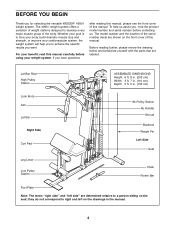
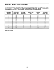
... differences in the left column refer to friction between the cables, pulleys, and weight guides. WEIGHT RESISTANCE CHART The chart below shows the approximate weight resistance at each exercise station. Number of Weights 1 2 3 4 5 6 7 8 9 10 11 12 High Pulley Station (lbs.) 33 43 53 64 73 85 98 112 123 133 149 158 Ab Pulley Station (lbs.) 35 45 56 65 71 83 98... 73 76 83 88 95 101 Press Arm (lbs.) 38 42 50 53 60 65 74 80 85 92 98 103 Low Pulley Station (lbs.) 36 46 56 68 79 89 101 115 128 143 153 161 Note: 1 lb. = 0.45 kg 25 The numbers in individual weights and due to the 11-lb...
... differences in the left column refer to friction between the cables, pulleys, and weight guides. WEIGHT RESISTANCE CHART The chart below shows the approximate weight resistance at each exercise station. Number of Weights 1 2 3 4 5 6 7 8 9 10 11 12 High Pulley Station (lbs.) 33 43 53 64 73 85 98 112 123 133 149 158 Ab Pulley Station (lbs.) 35 45 56 65 71 83 98... 73 76 83 88 95 101 Press Arm (lbs.) 38 42 50 53 60 65 74 80 85 92 98 103 Low Pulley Station (lbs.) 36 46 56 68 79 89 101 115 128 143 153 161 Note: 1 lb. = 0.45 kg 25 The numbers in individual weights and due to the 11-lb...
Uk Manual
Page 26
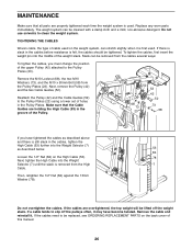
Do not use solvents to slip off the weight stack. Then, retighten the 1/2" Nut (84) against the 13mm Washer (78). If the cables need to be tightened. Remove the M10 Locknut (68), the two M10 Washers (73), and the M10 x 50mm Bolt (58) from the cables several ways: To tighten the cables, you have become twisted. MAINTENANCE Make sure that the Cable Guides are holding...
Do not use solvents to slip off the weight stack. Then, retighten the 1/2" Nut (84) against the 13mm Washer (78). If the cables need to be tightened. Remove the M10 Locknut (68), the two M10 Washers (73), and the M10 x 50mm Bolt (58) from the cables several ways: To tighten the cables, you have become twisted. MAINTENANCE Make sure that the Cable Guides are holding...
Uk Manual
Page 28
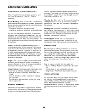
... minutes of stretching. Weight Loss-To lose weight, use a low amount of resistance and increase the number of repetitions in each set smoothly and without pausing. Cross Training-Combine strength training and aerobic exercise by following this type of program: • Strength workouts on Monday, Wednesday, and Friday. • 20 to determine the appropriate length of time for each EXERCISE FORM Move through the full...
... minutes of stretching. Weight Loss-To lose weight, use a low amount of resistance and increase the number of repetitions in each set smoothly and without pausing. Cross Training-Combine strength training and aerobic exercise by following this type of program: • Strength workouts on Monday, Wednesday, and Friday. • 20 to determine the appropriate length of time for each EXERCISE FORM Move through the full...
Uk Manual
Page 29
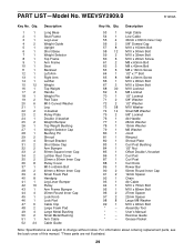
... Key No. Qty. Exercise Guide * - Grease Packet Note: Specifications are not illustrated. 29 Qty. Assembly Tool * - Description Key No. Description 1 1 Long Base 2 1 Seat Frame 3 1 Leg Lever 4 2 Weight Guide 5 1 Upright 6 1 Short Base 7 1 Weight Selector 8 1 Top Frame 9 1 Arm Frame 10 1 Seat 11 1 Backrest 12 1 Left Arm 13 1 Right Arm 14 1 Lat Bar 15 12 Weight 16 1 Top Weight 17 2 Handle 18 1 Weight Pin 19 2 Pad Tube 20 6 M10 Curved Washer 21 1 Leg 22 2 U-bracket 23 2 Pulley Plate...
... Key No. Qty. Exercise Guide * - Grease Packet Note: Specifications are not illustrated. 29 Qty. Assembly Tool * - Description Key No. Description 1 1 Long Base 2 1 Seat Frame 3 1 Leg Lever 4 2 Weight Guide 5 1 Upright 6 1 Short Base 7 1 Weight Selector 8 1 Top Frame 9 1 Arm Frame 10 1 Seat 11 1 Backrest 12 1 Left Arm 13 1 Right Arm 14 1 Lat Bar 15 12 Weight 16 1 Top Weight 17 2 Handle 18 1 Weight Pin 19 2 Pad Tube 20 6 M10 Curved Washer 21 1 Leg 22 2 U-bracket 23 2 Pulley Plate...
Uk Manual
Page 32
ORDERING REPLACEMENT PARTS To order replacement parts, please see the PART LIST and the EXPLODED DRAWING near the end of this manual) Part No. 292614 R1209A Printed in China © 2009 ICON IP, Inc. To help us assist you, be prepared to provide the following information when contacting us: • the model number and serial number of the product (see the front cover of this manual) • the name of the product (see the front cover of this manual) • the key number and description of the replacement part(s) (see the front cover of this manual.
ORDERING REPLACEMENT PARTS To order replacement parts, please see the PART LIST and the EXPLODED DRAWING near the end of this manual) Part No. 292614 R1209A Printed in China © 2009 ICON IP, Inc. To help us assist you, be prepared to provide the following information when contacting us: • the model number and serial number of the product (see the front cover of this manual) • the name of the product (see the front cover of this manual) • the key number and description of the replacement part(s) (see the front cover of this manual.


