Service Manual
Page 1
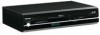
This Service Manual describes replacement parts for the green product. TOSHIBA CORPORATION 2008 Published in this green product, use the part(s) described in Japan, Jan. 2008 GREEN For (*1) and (*2), see the next page. When repairing this manual and lead-free solder (*2). SERVICE MANUAL FILE NO. 810-200803GR DVD Video Recorder /Video Cassette Recorder D-VR610KU The above model is classified as a green product (*1), as indicated by the underlined serial number.
This Service Manual describes replacement parts for the green product. TOSHIBA CORPORATION 2008 Published in this green product, use the part(s) described in Japan, Jan. 2008 GREEN For (*1) and (*2), see the next page. When repairing this manual and lead-free solder (*2). SERVICE MANUAL FILE NO. 810-200803GR DVD Video Recorder /Video Cassette Recorder D-VR610KU The above model is classified as a green product (*1), as indicated by the underlined serial number.

Service Manual
Page 18
Unhook two places and detach the Dust Cover. 6. Rotate the gear in the direction of the arrow manually as shown below until the tray descends. 7. Remove the DVD Mechanism & DVD Main BOARD Assembly. 5. Remove the Cover Top. 2. Remove the Front Bracket. 4. How to Eject Manually Note: When rotating the gear, be careful not to damage the gear. 1. Remove the Panel Front. 3. Front Bracket Hook View for A A Rotate this gear in the direction of the arrow Dust Cover Panel Front 1-6-6 E9KGADC Pull the tray out manually and remove a disc. 3.
Unhook two places and detach the Dust Cover. 6. Rotate the gear in the direction of the arrow manually as shown below until the tray descends. 7. Remove the DVD Mechanism & DVD Main BOARD Assembly. 5. Remove the Cover Top. 2. Remove the Front Bracket. 4. How to Eject Manually Note: When rotating the gear, be careful not to damage the gear. 1. Remove the Panel Front. 3. Front Bracket Hook View for A A Rotate this gear in the direction of the arrow Dust Cover Panel Front 1-6-6 E9KGADC Pull the tray out manually and remove a disc. 3.
Service Manual
Page 51
... number shown on these components, read the parts list in μF (P = 10-6 μF). 5. All voltages are indicated in this manual carefully. Do not use of these drawings for higher voltage, wattage, etc. All capacitance values are DC voltages unless otherwise specified. 1-13-1... the protection afforded by them cannot necessarily be slightly different or amended since these special safety characteristics are indicated in this manual and its supplements; Before replacing any of substitute replacement parts that have these drawings were prepared. 2. Standard Notes WARNING...
... number shown on these components, read the parts list in μF (P = 10-6 μF). 5. All voltages are indicated in this manual carefully. Do not use of these drawings for higher voltage, wattage, etc. All capacitance values are DC voltages unless otherwise specified. 1-13-1... the protection afforded by them cannot necessarily be slightly different or amended since these special safety characteristics are indicated in this manual and its supplements; Before replacing any of substitute replacement parts that have these drawings were prepared. 2. Standard Notes WARNING...
Service Manual
Page 52
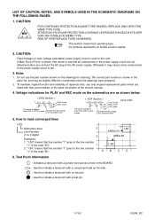
... voltage for both PLAY & STOP modes Indicates that line number "1" goes to 3 digits) Examples: 2 AREA B1 1. To maintain original function and reliability of the service manual. 4. "1-B1" means that the voltage is not consistent here. < VCR Section > 123 PLAY mode 5.0 5.0 REC mode (2.5) DVD mode The same voltage for ordering.
... voltage for both PLAY & STOP modes Indicates that line number "1" goes to 3 digits) Examples: 2 AREA B1 1. To maintain original function and reliability of the service manual. 4. "1-B1" means that the voltage is not consistent here. < VCR Section > 123 PLAY mode 5.0 5.0 REC mode (2.5) DVD mode The same voltage for ordering.

Service Manual
Page 85
Don't degrade the safety of these components, read carefully the product safety notice in this service manual. have special characteristics important to safety. Before replacing any of the product through improper servicing. X20 P000501330 1VMN24593 OWNERS MANUAL E9KGAUD X22A P000501340 1VMN24594 QUICK GUIDE E9KGAUD X22B P000501350 1VMN24595 QUICK GUIDE(ES) E9KGAUD 20080112 1-19...
Don't degrade the safety of these components, read carefully the product safety notice in this service manual. have special characteristics important to safety. Before replacing any of the product through improper servicing. X20 P000501330 1VMN24593 OWNERS MANUAL E9KGAUD X22A P000501340 1VMN24594 QUICK GUIDE E9KGAUD X22B P000501350 1VMN24595 QUICK GUIDE(ES) E9KGAUD 20080112 1-19...
Service Manual
Page 86
... P000501460 WX1E9B00-006 FFC CABLE 5P FFC/P1.25/120 20080112 1-20-1 E9KGAEL Parts that are not assigned part numbers are included in this service manual. P1 P000501380 1VSA17727 BOARD MCV Consists of Capacitors and Resistors are included in BOARD POWER SWITCH (MCV-B) . Description ! AC1001 P000501440 WAV0172LW022 POWER CORD WITH A GND...
... P000501460 WX1E9B00-006 FFC CABLE 5P FFC/P1.25/120 20080112 1-20-1 E9KGAEL Parts that are not assigned part numbers are included in this service manual. P1 P000501380 1VSA17727 BOARD MCV Consists of Capacitors and Resistors are included in BOARD POWER SWITCH (MCV-B) . Description ! AC1001 P000501440 WAV0172LW022 POWER CORD WITH A GND...


