Service Manual
Page 1
TOSHIBA CORPORATION 2008 Published in this manual and lead-free solder (*2). For (*1) and (*2), see the next page. SERVICE MANUAL FILE NO. 810-200803GR DVD Video Recorder /Video Cassette Recorder D-VR610KU The above model is classified as a green product (*1), as indicated by the underlined serial number. This Service Manual describes replacement parts for the green product. When repairing this green product, use the part(s) described in Japan, Jan. 2008 GREEN
TOSHIBA CORPORATION 2008 Published in this manual and lead-free solder (*2). For (*1) and (*2), see the next page. SERVICE MANUAL FILE NO. 810-200803GR DVD Video Recorder /Video Cassette Recorder D-VR610KU The above model is classified as a green product (*1), as indicated by the underlined serial number. This Service Manual describes replacement parts for the green product. When repairing this green product, use the part(s) described in Japan, Jan. 2008 GREEN
Service Manual
Page 3
... SECTION DVD VIDEO RECORDER & VIDEO CASSETTE RECORDER D-VR610KU Main Section I Specifications I Preparation for Servicing I Adjustment Procedures I Schematic Diagrams I BOARD's I Exploded Views I Parts List TABLE OF CONTENTS Specifications 1-1-1 Laser Beam Safety Precautions 1-2-1 Important Safety Precautions 1-3-1 Standard Notes for Servicing 1-4-1 Preparation for Servicing 1-5-1 Cabinet Disassembly Instructions 1-6-1 Electrical Adjustment Instructions 1-7-1 How to Initialize the DVD Recorder & VCR 1-8-1 Firmware Renewal Mode 1-9-1 Troubleshooting 1-10-1 Function Indicator Symbols...
... SECTION DVD VIDEO RECORDER & VIDEO CASSETTE RECORDER D-VR610KU Main Section I Specifications I Preparation for Servicing I Adjustment Procedures I Schematic Diagrams I BOARD's I Exploded Views I Parts List TABLE OF CONTENTS Specifications 1-1-1 Laser Beam Safety Precautions 1-2-1 Important Safety Precautions 1-3-1 Standard Notes for Servicing 1-4-1 Preparation for Servicing 1-5-1 Cabinet Disassembly Instructions 1-6-1 Electrical Adjustment Instructions 1-7-1 How to Initialize the DVD Recorder & VCR 1-8-1 Firmware Renewal Mode 1-9-1 Troubleshooting 1-10-1 Function Indicator Symbols...
Service Manual
Page 4
... format: MPEG Audio recording format Sampling frequency: 48 kHz Compression format: Dolby Digital/LPCM (XP Recording mode only) Input/Output Video input Input 1 (rear), 2 (front) Input level: 1 Vp-p (75Ω) Jacks: RCA jack Video output Output 1 (rear) Output level: 1 Vp-p (75Ω) Jack: RCA jack S-video input Input 1 (rear) Y (luminance) - Input level: 286 mVp-p (75Ω) Jacks: 4 pin mini DIN S-video output Output 1 (rear) Y (luminance) - Output level: 1 Vp-p (75Ω) C (color) - SPECIFICATIONS General System DVD-RW/-R, DVD+RW/+R, DVD-video, CD-DA, CD-RW/-R, VHS cassette tape VCR...
... format: MPEG Audio recording format Sampling frequency: 48 kHz Compression format: Dolby Digital/LPCM (XP Recording mode only) Input/Output Video input Input 1 (rear), 2 (front) Input level: 1 Vp-p (75Ω) Jacks: RCA jack Video output Output 1 (rear) Output level: 1 Vp-p (75Ω) Jack: RCA jack S-video input Input 1 (rear) Y (luminance) - Input level: 286 mVp-p (75Ω) Jacks: 4 pin mini DIN S-video output Output 1 (rear) Y (luminance) - Output level: 1 Vp-p (75Ω) C (color) - SPECIFICATIONS General System DVD-RW/-R, DVD+RW/+R, DVD-video, CD-DA, CD-RW/-R, VHS cassette tape VCR...
Service Manual
Page 6
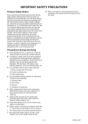
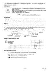
... by replacing them with components rated for higher voltage, wattage, etc. H. J. on schematics and in order to spurious radiation. Precautions during Servicing A. B. Examples: RF converters, RF cables, noise blocking capacitors, and noise blocking filters, etc. Note especially: 1) Insulation tape 2) PVC tubing 3) Spacers 4) Insulators for hazardous live parts. When connecting or disconnecting the internal connectors, first, disconnect the AC plug from...
... by replacing them with components rated for higher voltage, wattage, etc. H. J. on schematics and in order to spurious radiation. Precautions during Servicing A. B. Examples: RF converters, RF cables, noise blocking capacitors, and noise blocking filters, etc. Note especially: 1) Insulation tape 2) PVC tubing 3) Spacers 4) Insulators for hazardous live parts. When connecting or disconnecting the internal connectors, first, disconnect the AC plug from...

Service Manual
Page 7
...): Insert load Z between B (earth ground, power cord plug prongs) and externally exposed accessible parts (RF terminals, antenna terminals, video and audio input and output terminals, microphone jacks, earphone jacks, etc.) is lower than or equal to the specified value in parallel Leakage Current (i) i ≤ 0.5 mA Peak Earth Ground (B) to verify compliance with safety standards. 1. Use an AC voltmeter to confirm...
...): Insert load Z between B (earth ground, power cord plug prongs) and externally exposed accessible parts (RF terminals, antenna terminals, video and audio input and output terminals, microphone jacks, earphone jacks, etc.) is lower than or equal to the specified value in parallel Leakage Current (i) i ≤ 0.5 mA Peak Earth Ground (B) to verify compliance with safety standards. 1. Use an AC voltmeter to confirm...
Service Manual
Page 8
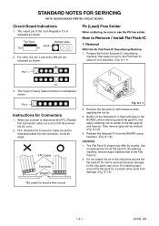
... ICs is fixed with tweezers while applying the hot air. 3. Put masking tape around the flat pack-IC for Connectors 1. Remove the flat pack-IC with glue to use the Pb free solder. Then remove (glue will...View Input Out In Bottom View 2. Pin 1 Instructions for over 6 seconds because damage to protect other ICs, pin 1 and every fifth pin are indicated as shown. FFC (Flexible Foil Connector) cable should be melted). (Fig. S-1-6) CAUTION: 1. Do not supply hot air to the chip parts around the flat pack-IC to the chip parts may differ by models. S-1-1 2. when removing...
... ICs is fixed with tweezers while applying the hot air. 3. Put masking tape around the flat pack-IC for Connectors 1. Remove the flat pack-IC with glue to use the Pb free solder. Then remove (glue will...View Input Out In Bottom View 2. Pin 1 Instructions for over 6 seconds because damage to protect other ICs, pin 1 and every fifth pin are indicated as shown. FFC (Flexible Foil Connector) cable should be melted). (Fig. S-1-6) CAUTION: 1. Do not supply hot air to the chip parts around the flat pack-IC to the chip parts may differ by models. S-1-1 2. when removing...
Service Manual
Page 12
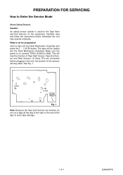
... operate erratically. The tape will stay valid.) See Fig. 1. Make sure the power is used for preparation Insert a tape into the Deck Mechanism Assembly. Q1503 Q1504 S-INH TP502 Fig. 1 Note: Because the Tape End Sensors are connected before plugging in the unit, the function of the tape to avoid tape damage. 1-5-1 E9KGAPFS What to do not run a tape all the way to the start...
... operate erratically. The tape will stay valid.) See Fig. 1. Make sure the power is used for preparation Insert a tape into the Deck Mechanism Assembly. Q1503 Q1504 S-INH TP502 Fig. 1 Note: Because the Tape End Sensors are connected before plugging in the unit, the function of the tape to avoid tape damage. 1-5-1 E9KGAPFS What to do not run a tape all the way to the start...
Service Manual
Page 13
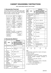
... Bracket [5] BOARD Front Jack [10] Motor DC Fan [9] Fan Holder [6] DVD Mechanism & DVD Main BOARD Assembly [7] Dust Cover [12] BOARD Power Supply [11] Panel Rear [8] Panel Rear Unit [13] BOARD Holder [15] Deck Assembly [16] BOARD Power Switch [17] BOARD DVD open / close Switch [14] VCR Chassis Unit [18] BOARD Main [19] Deck Pedestal 2. Supply [13] BOARD Holder D7 4(S-12), Plate Earth --- When reassembling, follow the...
... Bracket [5] BOARD Front Jack [10] Motor DC Fan [9] Fan Holder [6] DVD Mechanism & DVD Main BOARD Assembly [7] Dust Cover [12] BOARD Power Supply [11] Panel Rear [8] Panel Rear Unit [13] BOARD Holder [15] Deck Assembly [16] BOARD Power Switch [17] BOARD DVD open / close Switch [14] VCR Chassis Unit [18] BOARD Main [19] Deck Pedestal 2. Supply [13] BOARD Holder D7 4(S-12), Plate Earth --- When reassembling, follow the...
Service Manual
Page 19
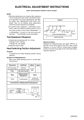
... the picture. Tape Measurement Equipment Spec. ELECTRICAL ADJUSTMENT INSTRUCTIONS NOTE: BOARD MEANS PRINTED CIRCUIT BOARD. Figure 1 EXT. FL8A Oscilloscope 6.5H±1H (416μs±64μs) Connections of the CH2 head switching pulse waveform. Test point Adj.Point Mode Input TP751(V-OUT) VR1501 TP302(RF-SW) (Switching Point) GND (BOARD MAIN) PLAY (SP) ----- NOTE: 1.Electrical adjustments are required after all repairs and replacements...
... the picture. Tape Measurement Equipment Spec. ELECTRICAL ADJUSTMENT INSTRUCTIONS NOTE: BOARD MEANS PRINTED CIRCUIT BOARD. Figure 1 EXT. FL8A Oscilloscope 6.5H±1H (416μs±64μs) Connections of the CH2 head switching pulse waveform. Test point Adj.Point Mode Input TP751(V-OUT) VR1501 TP302(RF-SW) (Switching Point) GND (BOARD MAIN) PLAY (SP) ----- NOTE: 1.Electrical adjustments are required after all repairs and replacements...
Service Manual
Page 20
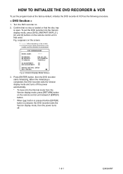
Fig. a Version Display Mode Screen 3. To put the program back at the factory-default, initialize the DVD recorder & VCR as the following procedure. < DVD Section > 1. F/W VERSION DISP MODEL NAME : FE VERSION : BE VERSION : TT VERSION : ******* R50_015_000 WL5T34280H1E T50014WLU LD ADJUSTMENT : OK DISC ADJUSTMENT : OK DEFAULT SETTING : ENTER EXIT : RETURN Fig. Confirm that no disc is loaded or that order. Press [ENTER] button, then the DVD recorder starts initializing. Turn the DVD recorder on the remote control unit...
Fig. a Version Display Mode Screen 3. To put the program back at the factory-default, initialize the DVD recorder & VCR as the following procedure. < DVD Section > 1. F/W VERSION DISP MODEL NAME : FE VERSION : BE VERSION : TT VERSION : ******* R50_015_000 WL5T34280H1E T50014WLU LD ADJUSTMENT : OK DISC ADJUSTMENT : OK DEFAULT SETTING : ENTER EXIT : RETURN Fig. Confirm that no disc is loaded or that order. Press [ENTER] button, then the DVD recorder starts initializing. Turn the DVD recorder on the remote control unit...
Service Manual
Page 21
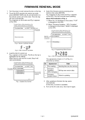
... the tray will start automatically. * Firmware Version differs depending on the models, and this time, no button is described as the default. Fig. c Update Disc Screen Fig. Turn the power on and remove the disc on the screen. To put the DVD recorder into the memory Firmware 2 Updating... Firm Update Mode ver. Please insert a disc. Fig. XX% Complete." Firm Update Mode WL5T34280H1E ver. Load the disc for version up mode, press [INSTANT SKIP], [6], [5], and [4] buttons on the remote control...
... the tray will start automatically. * Firmware Version differs depending on the models, and this time, no button is described as the default. Fig. c Update Disc Screen Fig. Turn the power on and remove the disc on the screen. To put the DVD recorder into the memory Firmware 2 Updating... Firm Update Mode ver. Please insert a disc. Fig. XX% Complete." Firm Update Mode WL5T34280H1E ver. Load the disc for version up mode, press [INSTANT SKIP], [6], [5], and [4] buttons on the remote control...
Service Manual
Page 25
... the Pin(3) terminal of No the RS1501 (remote control receiver)? Check AL+5V line and replace P1 (BOARD MCV) or P3 (BOARD POWER SUPPLY) if defective. Or replace remote control unit (X1). Check the key switches and their periphery, and replace P1 (BOARD MCV) if defective. Replace P1 (BOARD MCV). DVD PLAY ----- Are the contact point and the installation state of IC1501? Yes No Is the...
... the Pin(3) terminal of No the RS1501 (remote control receiver)? Check AL+5V line and replace P1 (BOARD MCV) or P3 (BOARD POWER SUPPLY) if defective. Or replace remote control unit (X1). Check the key switches and their periphery, and replace P1 (BOARD MCV) if defective. Replace P1 (BOARD MCV). DVD PLAY ----- Are the contact point and the installation state of IC1501? Yes No Is the...
Service Manual
Page 31
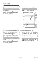
... of the RS1501 (remote control receiver) when the remote control unit is possible from the unit.) Is 5V voltage supplied to the Pin(5) of No the key switches normal? 3 VCR Section FLOW CHART NO.1 The key operation is not functioning. Re-install some key switches correctly or replace P1 (BOARD MCV) if defective. Check AL+5V line and replace P1 (BOARD MCV) or P3 (BOARD POWER SUPPLY) if defective...
... of the RS1501 (remote control receiver) when the remote control unit is possible from the unit.) Is 5V voltage supplied to the Pin(5) of No the key switches normal? 3 VCR Section FLOW CHART NO.1 The key operation is not functioning. Re-install some key switches correctly or replace P1 (BOARD MCV) if defective. Check AL+5V line and replace P1 (BOARD MCV) or P3 (BOARD POWER SUPPLY) if defective...
Service Manual
Page 39
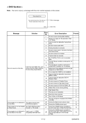
... CGMS picture input. 12 This program is not recordable Set "DVD-RW Recording in normal REC condition for finalized DVD-R/RW/ +R/+RW. 1 This program is not readable." - 14 Cannot write the data after recovering SMALL VMGI. - 15 Cannot write the data after trying three times. - 4 An error occurs with the error number appears on this disc. compatible DVD-RW disc. Recording Error You cannot record on the screen. Error Description Priority 1 An error occurs during data reading...
... CGMS picture input. 12 This program is not recordable Set "DVD-RW Recording in normal REC condition for finalized DVD-R/RW/ +R/+RW. 1 This program is not readable." - 14 Cannot write the data after recovering SMALL VMGI. - 15 Cannot write the data after trying three times. - 4 An error occurs with the error number appears on this disc. compatible DVD-RW disc. Recording Error You cannot record on the screen. Error Description Priority 1 An error occurs during data reading...
Service Manual
Page 40
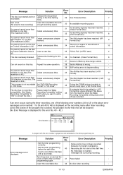
.... programming again. Repeat the same operation. 38 Sector Address is already finalized. Can not record on and set the clock correctly then set timer 41 Power failed - Error Description Priority - This disc is wrong. - 39 BUP writing error of control information. 10 You cannot record on one disc. Format" to "VR mode". 45 During the CGMS picture (possible to record once) input. (+VR Format Disc) 12 The disc has no recording compatibility. (Set "Make Recording Compatible" to "ON" to convert the disk...
.... programming again. Repeat the same operation. 38 Sector Address is already finalized. Can not record on and set the clock correctly then set timer 41 Power failed - Error Description Priority - This disc is wrong. - 39 BUP writing error of control information. 10 You cannot record on one disc. Format" to "VR mode". 45 During the CGMS picture (possible to record once) input. (+VR Format Disc) 12 The disc has no recording compatibility. (Set "Make Recording Compatible" to "ON" to convert the disk...
Service Manual
Page 41
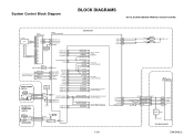
... H-A-COMP VIDEO-SW1 VIDEO-SW2 VIDEO-SW3 TO Hi-Fi AUDIO BLOCK DIAGRAM TO AUDIO BLOCK DIAGRAM TO VIDEO BLOCK DIAGRAM TO VIDEO INPUT SELECT BLOCK DIAGRAM OUTPUT-SELECT OUTPUT-SELECT2 OUTPUT-SELECT2 OUTPUT-SELECT AUDIO-SW1 AUDIO-SW2 TO VIDEO OUTPUT SELECT BLOCK DIAGRAM TO AUDIO INPUT/OUTPUT SELECT BLOCK DIAGRAM 1-12-1 VCR-LED 94 VCR-LED 95 DVD-LED 96 DVD-LED 97 D1563 D1562 VCR DVD AL+5V IC101 MAIN MICRO CONTROLLER SYS-RESET 44 S-DATA-OUT 16 S-DATA-IN 15 S-CLOCK 14...
... H-A-COMP VIDEO-SW1 VIDEO-SW2 VIDEO-SW3 TO Hi-Fi AUDIO BLOCK DIAGRAM TO AUDIO BLOCK DIAGRAM TO VIDEO BLOCK DIAGRAM TO VIDEO INPUT SELECT BLOCK DIAGRAM OUTPUT-SELECT OUTPUT-SELECT2 OUTPUT-SELECT2 OUTPUT-SELECT AUDIO-SW1 AUDIO-SW2 TO VIDEO OUTPUT SELECT BLOCK DIAGRAM TO AUDIO INPUT/OUTPUT SELECT BLOCK DIAGRAM 1-12-1 VCR-LED 94 VCR-LED 95 DVD-LED 96 DVD-LED 97 D1563 D1562 VCR DVD AL+5V IC101 MAIN MICRO CONTROLLER SYS-RESET 44 S-DATA-OUT 16 S-DATA-IN 15 S-CLOCK 14...

Service Manual
Page 45
... BOARD MAIN REC VIDEO SIGNAL TO DIGITAL SIGNAL PROCESS BLOCK DIAGRAM VIDEO-Y/CVBS VIDEO-C CN701 CN2201 20 VIDEO-Y/CVBS-IN 20 22 VIDEO-C-IN 22 Q2305 BUFFER IC2805 (INPUT SELECT) 19 BUFFER LPF Y1 13 MUTE TO VIDEO BLOCK VCR-VIDEO 20 BUFFER + DIAGRAM VIDEO1 8 VIDEO2 10 PB/EE 12 MUTE (VCR DVD DUBBING) VCR-VIDEO(DUB) TO VIDEO BLOCK DIAGRAM YC G G JK2401 S-VIDEO IN1 REAR JK2804 VIDEO - Video Input Select Block Diagram NOTE: BOARD MEANS...
... BOARD MAIN REC VIDEO SIGNAL TO DIGITAL SIGNAL PROCESS BLOCK DIAGRAM VIDEO-Y/CVBS VIDEO-C CN701 CN2201 20 VIDEO-Y/CVBS-IN 20 22 VIDEO-C-IN 22 Q2305 BUFFER IC2805 (INPUT SELECT) 19 BUFFER LPF Y1 13 MUTE TO VIDEO BLOCK VCR-VIDEO 20 BUFFER + DIAGRAM VIDEO1 8 VIDEO2 10 PB/EE 12 MUTE (VCR DVD DUBBING) VCR-VIDEO(DUB) TO VIDEO BLOCK DIAGRAM YC G G JK2401 S-VIDEO IN1 REAR JK2804 VIDEO - Video Input Select Block Diagram NOTE: BOARD MEANS...
Service Manual
Page 52
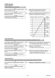
... indications for PLAY and REC mode on foil side. : Used to indicate a test point with no test pin. : Used to indicate a test point with their part numbers in the power supply circuit are not defective before you connect the AC plug to 3 digits) Examples: 2 AREA B1 1. CAUTION: Fixed Voltage (or Auto voltage selectable) power supply circuit is not consistent here. < VCR Section > 123 PLAY mode 5.0 5.0 REC mode (2.5) DVD mode The same...
... indications for PLAY and REC mode on foil side. : Used to indicate a test point with no test pin. : Used to indicate a test point with their part numbers in the power supply circuit are not defective before you connect the AC plug to 3 digits) Examples: 2 AREA B1 1. CAUTION: Fixed Voltage (or Auto voltage selectable) power supply circuit is not consistent here. < VCR Section > 123 PLAY mode 5.0 5.0 REC mode (2.5) DVD mode The same...
Service Manual
Page 77
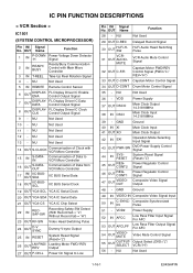
... Not Used 5 IN REMOTE Remote Control Sensor 6 OUT DISPLAYENA FL Display Driver IC Enable Control Output Signal 7 OUT DISPLAYDATA FL Display Driver IC Data Control Output Signal 8 OUT DISPLAYCLK FL Display Driver IC Clock Control Output Signal 9 - NU Not Used 10 - VDD Power Supply 37 OUT OSCO 38 IN OSCI Main Clock Output 14.31818MHz Main Clock Input 14.31818MHz 39 - NU Not Used 1-16-1 E9KGAPIN NU Not Used 29 OUT D-REC Delayed Record Signal 30 OUT Hi-Fi-HSW VCR31 OUT AUDIO...
... Not Used 5 IN REMOTE Remote Control Sensor 6 OUT DISPLAYENA FL Display Driver IC Enable Control Output Signal 7 OUT DISPLAYDATA FL Display Driver IC Data Control Output Signal 8 OUT DISPLAYCLK FL Display Driver IC Clock Control Output Signal 9 - NU Not Used 10 - VDD Power Supply 37 OUT OSCO 38 IN OSCI Main Clock Output 14.31818MHz Main Clock Input 14.31818MHz 39 - NU Not Used 1-16-1 E9KGAPIN NU Not Used 29 OUT D-REC Delayed Record Signal 30 OUT Hi-Fi-HSW VCR31 OUT AUDIO...
Service Manual
Page 78
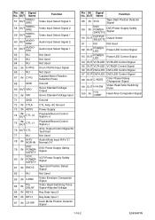
... (-) Playback/Record Control Signal (-) 76 OUT CTL Amp. OUT Name Function 88 IN ST-S Tape Start Position Detector Signal 89 IN DVD POWERSAFETY2 DVD Power Supply Safety Signal 90 OUT OUTPUTSELECT2 Output Select 91 - NU Not Used Not Used 65 IN D-PFG Drum PG/FG Input Signal 66 - NU 64 - GND Ground 72 IN CTLA CTL Amp. NU Not Used 83 IN V-ENV 84 IN PGDELAY Video Envelope Comparator Signal Video Head Switching...
... (-) Playback/Record Control Signal (-) 76 OUT CTL Amp. OUT Name Function 88 IN ST-S Tape Start Position Detector Signal 89 IN DVD POWERSAFETY2 DVD Power Supply Safety Signal 90 OUT OUTPUTSELECT2 Output Select 91 - NU Not Used Not Used 65 IN D-PFG Drum PG/FG Input Signal 66 - NU 64 - GND Ground 72 IN CTLA CTL Amp. NU Not Used 83 IN V-ENV 84 IN PGDELAY Video Envelope Comparator Signal Video Head Switching...


