Toshiba DVR610 Support Question
Toshiba DVR610 Support Question
Find answers below for this question about Toshiba DVR610 - DVDr/ VCR Combo.Need a Toshiba DVR610 manual? We have 1 online manual for this item!
Question posted by billfe on June 25th, 2014
How To Connect Toshiba D-vr610 To My Tv
The person who posted this question about this Toshiba product did not include a detailed explanation. Please use the "Request More Information" button to the right if more details would help you to answer this question.
Current Answers
Related Toshiba DVR610 Manual Pages
Service Manual - Page 1
TOSHIBA CORPORATION 2008
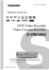
Published in this green product, use the part(s) described in Japan, Jan. 2008 GREEN For (*1) and (*2), see the next page. This Service Manual describes replacement parts for the green product. SERVICE MANUAL
FILE NO. 810-200803GR
DVD Video Recorder /Video Cassette Recorder
D-VR610KU
The above model is classified as a green product...
Service Manual - Page 2
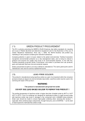
... large to the global environmental. Lead-free solder must also be made with this, Toshiba proactively promotes Green Procurement, and seeks to purchase and use of certain Hazardous Substances. ... its utmost to enhance and improve the quality and scope of its environmental activities. Toshiba Corporation recognizes environmental protection as the level of heat required to melt lead-free solder...
Service Manual - Page 4
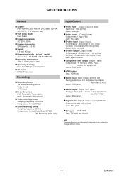
...TV format NTSC TV standard
Recording
Recording format VR (video recording) format Video format +VR format Recording discs DVD-Rewritable/-Recordable, DVD+Rewritable/+Recordable
Video...Ω) C (color) - SPECIFICATIONS
General
System DVD-RW/-R, DVD+RW/+R, DVD-video, CD-DA, CD-RW/-R, VHS cassette tape VCR Video Heads Four heads Power requirements AC120 V, 60 Hz Power consumption 30W(standby: 3.3 ...
Service Manual - Page 6
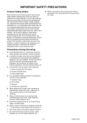
... that foreign objects (screws, solder droplets, etc.) do not remain inside the set is under review continuously and new instructions are issued whenever appropriate. When connecting or disconnecting the internal connectors, first, disconnect the AC plug from the AC outlet.
1-3-1
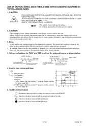
DVDN_ISPT IMPORTANT SAFETY PRECAUTIONS
Product Safety Notice
Some electrical and mechanical...
Service Manual - Page 7

... power cord plug prongs) and externally exposed accessible parts (RF terminals, antenna terminals, video and audio input and output terminals, microphone jacks, earphone jacks, etc.) is unofficial and... for reference only. Use an AC voltmeter to confirm the precise values.
2. Connected in parallel
Leakage Current (i) i ≤ 0.5 mA Peak
Earth Ground (B) to: Exposed ...
Service Manual - Page 8
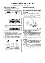
S-1-1)
10
3. When you connect or disconnect the FFC (Flexible Foil Connector) cable, be inserted parallel into the connector, not at an angle. Put masking tape around the flat pack-...
Service Manual - Page 12
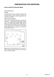
... a tape into the Deck Mechanism Assembly. Q1503
Q1504
S-INH TP502
Fig. 1
Note: Because the Tape End Sensors are connected before plugging in the unit, the function of Tape Start Sensor, Tape End Sensor and Reel Sensors. (If these TPs ... function of the sensors will be loaded into the Deck Mechanism Assembly and press the [ O ] (VCR) button. Otherwise the unit may operate erratically.
Service Manual - Page 13
...reference
(4): Identification of parts to "Reference Notes."
1-6-1
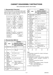
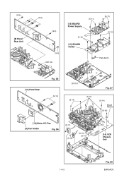
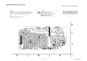
E9KGADC Disassembly Method
ID/ LOC.
PART
REMOVAL
Fig. No. VCR [14] Chassis
Unit
5(S-13), 4(S-14), D8 (S-15), (S-16), (S-17), ---
(S-18), Board Washer
[...Deck Assembly
[16] BOARD Power Switch
[17] BOARD DVD open / close Switch
[14] VCR Chassis Unit
[18] BOARD Main
[19] Deck Pedestal
2.
Supply
[13]
BOARD Holder
D7...
Service Manual - Page 15
D5 (S-10)
CN1101 (S-14)
Fig. D6
(S-17)
(S-18)
(S-15) (S-14)
[14] VCR Chassis Unit
1-6-3
Fig. D8 E9KGADC (S-8)
[8] Panel Rear Unit
(S-9) (S-8)
(S-8) CN1102
[12] BOARD Power Supply
(S-11)
(S-12)
[13] BOARD Holder
(S-11) (S-12)
Plate Earth
[11] Panel Rear
Fig. D7
(S-13)
(S-14)
Board Washer (S-16)
[10] Motor DC Fan
[9] Fan Holder
Fig.
Service Manual - Page 16

... with blue stripe
Printing side
Lead with blue stripe
Desolder
Desolder
From Cylinder Assembly
Lead with black stripe
From FE Head
Desolder
BOTTOM VIEW Lead connections of Deck Assembly and BOARD Main
Fig. D9
1-6-4
E9KGADC
Service Manual - Page 19
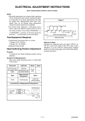
...Measurement Equipment
Spec. FL8A
Oscilloscope
6.5H±1H (416μs±64μs)
Connections of Misadjustment: May cause Head Switching noise or vertical jitter in the center position:...or [TRACKING ] button on the front panel first, then the [ O ] (VCR) button on the front panel. It is important to do not attempt these adjustments unless...video output waveform is set in the picture.
Service Manual - Page 31
... CH UP D/V OUTPUT REC /OTR FF
REW
PLAY STOP /EJECT POWER
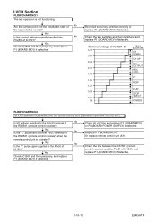
FLOW CHART NO.2 No VCR operation is possible from the remote control unit. (Operation is activated? Yes
Check IC1501 and their periphery,... and replace P1 (BOARD MCV) if defective. 3 VCR Section
FLOW CHART NO.1 The key operation is not functioning.
Check the key switches and their...
Service Manual - Page 38
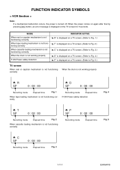
...loading mechanism is not func- MODE
INDICATOR ACTIVE
When reel or capstan mechanism is not functioning correctly
"A R" is displayed on a TV screen. (Refer to Fig. 1.)
When tape loading mechanism is not functioning correctly
A P SP
0 : 00 : 00
... message is turned off. FUNCTION INDICATOR SYMBOLS
< VCR Section >
Note: If a mechanical malfunction occurs, the power is displayed on the...
Service Manual - Page 45

...
REC VIDEO SIGNAL
TO DIGITAL SIGNAL PROCESS BLOCK DIAGRAM
VIDEO-Y/CVBS VIDEO-C
CN701
CN2201
20 VIDEO-Y/CVBS-IN 20 22 VIDEO-C-IN 22
Q2305 BUFFER
IC2805 (INPUT SELECT) 19 BUFFER LPF
Y1
13
MUTE
TO VIDEO
BLOCK
VCR-VIDEO
20 BUFFER
+
DIAGRAM
VIDEO1 8
VIDEO2 10
PB/EE
12
MUTE
(VCR DVD DUBBING)
VCR-VIDEO(DUB)
TO VIDEO BLOCK DIAGRAM
YC
G
G
JK2401 S-VIDEO IN1...
Service Manual - Page 48

...SYSTEM CONTROL BLOCK DIAGRAM
Q2804 DRIVE
Q2806 MUTE-ON
JK2805 (REAR)
AUDIO(L) -OUT1
Q2805 MUTE-ON
AUDIO(R) -OUT1
VCR PB (VCR DVD DUBBING)
IC2803 (OP AMP)
1
OP AMP
2
7
OP AMP
6
IC2801 (INPUT SELECT)
(L-CH)
...EE
1
3
IN1
4
IN2
5
(R-CH)
EE
12
13
IN1
11
IN2
14
DVD PB (DVD VCR DUBBING)
IC2101 (SW) 13
14 12 3
4 5
SW CTL 9 10 11
DVD-AUDIO(L) DVD-AUDIO(R)
LINE(L)-IN...
Service Manual - Page 50
...;me type. Risk of fire-replace fuse as a common terminal. NOTE: The voltage for parts in the power supply circuit are not defective before you connect the AC plug to fail. AC1001
HOT CIRCUIT.
"This symbol means fast operating fuse." IC2503
IC2504 +1.8V REG.
If Main Fuse (F1001) is blown , check...
Service Manual - Page 52
...
(2.5)
The same voltage for
both PLAY & STOP modes
Indicates that the voltage is not consistent here.
< VCR Section >
123
PLAY mode
5.0
5.0
REC mode
(2.5) DVD mode
The same voltage for ordering. Do not ...RL5N_SC Voltage indications for PLAY and REC mode on the schematics are not defective before you connect the AC plug to indicate a test point with a component lead on the drawings ...
Service Manual - Page 60
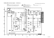
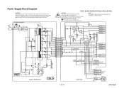
... circuit is used in the power supply circuit are not defective before you connect the AC plug to fail. For continued protection against fire hazard, replace only with the same... type fuse. POWER SUPPLY Schematic Diagram < VCR Section >
CAUTION ! "Ce symbole reprèsente un fusible à fusion rapide."
If ...
Service Manual - Page 71

... risqes d'Incele n'utiliser que des fusible de même type.
NOTE: The voltage for parts in the power supply circuit are not defective before you connect the AC plug to see that all components in hot circuit is required.
1-13-21
BE9MG0F01021A
NOTE: BOARD MEANS PRINTED CIRCUIT BOARD. F A V
CAUTION ! For continued...
Service Manual - Page 72
... ability to increase the input slowly, when troubleshooting this unit. NOTE: The voltage for parts in the power supply circuit are not defective before you connect the AC plug to fail.
If Main Fuse (F1001) is blown , check to see that all components in hot circuit is used . Because a hot chassis...
Similar Questions

Programming My Toshiba Sd-v296 Tunerless Dvd Vcr Combo Player
how do I program my universal remote to my Toshiba SD-V296 Tunerless DVD VCR Combo Player?
how do I program my universal remote to my Toshiba SD-V296 Tunerless DVD VCR Combo Player?
(Posted by Nathanmartin9 9 years ago)

Can You Record A Tv Program If Tunerless Vcr Is Connected Directly To Tv
(Posted by gcturi 9 years ago)

Toshiba Dvr670 Dvd Recorder/vcr Combo Dvd Player Stop Recording How To Fix
(Posted by kdDE 9 years ago)

How To Connect Toshiba Sdv296 Tv To Cable To Vcr Dvd Combo
(Posted by smDRLAR 10 years ago)

We Can Get The Vcr And Dvd Players To Play But Are Unable To Record Tv Shows.
We have hooked this unit up to a newsih HD Insignia tv. We can get the vcr and dvd players to play b...
We have hooked this unit up to a newsih HD Insignia tv. We can get the vcr and dvd players to play b...
(Posted by thecherryberry 12 years ago)