
Easy Smart SwitchUN User Guide
Page 2
... Overview...4 Logging Into the Switch...5 Managing System System...8 Overview...8 Supported Features...8 Configuring System Info...9 Viewing the System Information...9 Specifying the Device Description...9 Configuring IP...10 Configuring LED (Only for Certain Devices)...12 Configuring User Account...13 Backing up and Restoring the Switch...14 Saving the Current Configuration...14 Restoring to the Previous Configuration...15 Rebooting the Switch...17 Resetting the Switch...18 Upgrading the Firmware...19 Appendix: Default Parameters...21 Switching Switching...23 Overview...23 Supported Features...
... Overview...4 Logging Into the Switch...5 Managing System System...8 Overview...8 Supported Features...8 Configuring System Info...9 Viewing the System Information...9 Specifying the Device Description...9 Configuring IP...10 Configuring LED (Only for Certain Devices)...12 Configuring User Account...13 Backing up and Restoring the Switch...14 Saving the Current Configuration...14 Restoring to the Previous Configuration...15 Rebooting the Switch...17 Resetting the Switch...18 Upgrading the Firmware...19 Appendix: Default Parameters...21 Switching Switching...23 Overview...23 Supported Features...

Easy Smart SwitchUN User Guide
Page 3
...for Configuring IGMP Snooping...30 Network Requirements...30 Configuration Scheme...30 Configuration Steps...31 Example for Configuring LAG...32 Network Requirements...32 Configuration Steps...33 Appendix: Default Parameters...34 Monitoring Monitoring...36 Overview...36 Supported Features...36 Viewing Port Statistics...37 Configuring Port Mirror...39 Testing Cables...41 Configuring Loop Prevention...43 Appendix: Default Parameters...44 Configuring VLAN Overview...46 Configuring MTU VLAN...48 Configuring Port Based VLAN...49 Configuring 802.1Q VLAN...50 Configuring the VLAN...50 Configuring the...
...for Configuring IGMP Snooping...30 Network Requirements...30 Configuration Scheme...30 Configuration Steps...31 Example for Configuring LAG...32 Network Requirements...32 Configuration Steps...33 Appendix: Default Parameters...34 Monitoring Monitoring...36 Overview...36 Supported Features...36 Viewing Port Statistics...37 Configuring Port Mirror...39 Testing Cables...41 Configuring Loop Prevention...43 Appendix: Default Parameters...44 Configuring VLAN Overview...46 Configuring MTU VLAN...48 Configuring Port Based VLAN...49 Configuring 802.1Q VLAN...50 Configuring the VLAN...50 Configuring the...
Easy Smart SwitchUN User Guide
Page 5
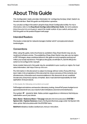
... used: PoE budget calculations are only examples and may vary by region or ISP. In this document is not guaranteed and will take full responsibility for network managers familiar with IT concepts and network terminologies. The symbol stands for configuring the Easy Smart Switch via the web interface. Throughout the guide, we will vary as the switch to the website https://www.tp-link.com/support, search the model number...
... used: PoE budget calculations are only examples and may vary by region or ISP. In this document is not guaranteed and will take full responsibility for network managers familiar with IT concepts and network terminologies. The symbol stands for configuring the Easy Smart Switch via the web interface. Throughout the guide, we will vary as the switch to the website https://www.tp-link.com/support, search the model number...

Easy Smart SwitchUN User Guide
Page 8
... based QoS optimize traffic on your device supports this feature, refer to the datasheet. ●● PoE configuration is a remote power supply function. Introduction Product Overview 1 Product Overview Easy Smart Switch is only available on certain devices. Storm control helps avoid network broadcast storm. ■■ PoE: PoE (Power over twisted-pair cables. With this feature, refer to the actual web interface. User Guide 4 The switch supports the following features: ■■ Traffic monitoring: Port mirroring, loop prevention and cable test enable the...
... based QoS optimize traffic on your device supports this feature, refer to the datasheet. ●● PoE configuration is a remote power supply function. Introduction Product Overview 1 Product Overview Easy Smart Switch is only available on certain devices. Storm control helps avoid network broadcast storm. ■■ PoE: PoE (Power over twisted-pair cables. With this feature, refer to the actual web interface. User Guide 4 The switch supports the following features: ■■ Traffic monitoring: Port mirroring, loop prevention and cable test enable the...
Easy Smart SwitchUN User Guide
Page 9
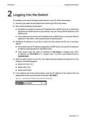
... default, the switch receives an IP address from a DHCP server (or a router that functions as 192.168.0.x ("x" ranges from the DHCP server. ■■ If the switch uses the static IP address of the switch. The supported web browsers include, but are in the same subnet. ■■ If the switch uses an IP address assigned by a DHCP server, set your PC to obtain an IP address automatically from 2 to , the following types...
... default, the switch receives an IP address from a DHCP server (or a router that functions as 192.168.0.x ("x" ranges from the DHCP server. ■■ If the switch uses the static IP address of the switch. The supported web browsers include, but are in the same subnet. ■■ If the switch uses an IP address assigned by a DHCP server, set your PC to obtain an IP address automatically from 2 to , the following types...
Easy Smart SwitchUN User Guide
Page 12
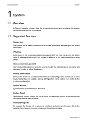
... configuration file to restore your switch to the previous configuration. Backup and Restore Backup and Restore is used to reset the switch to the factory default setting. System Reboot System Reboot is used to view the system information and configure the device description. User Guide 8 Firmware Upgrade To upgrade the firmware is to download the updated firmware. You can access the switch using IP address of the switch manually or using DHCP. All the settings will be cleared after the switch is reset. Managing System 1 System System 1.1 Overview In System module...
... configuration file to restore your switch to the previous configuration. Backup and Restore Backup and Restore is used to reset the switch to the factory default setting. System Reboot System Reboot is used to view the system information and configure the device description. User Guide 8 Firmware Upgrade To upgrade the firmware is to download the updated firmware. You can access the switch using IP address of the switch manually or using DHCP. All the settings will be cleared after the switch is reset. Managing System 1 System System 1.1 Overview In System module...
Easy Smart SwitchUN User Guide
Page 14
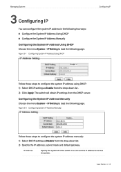
... Disable from the drop-down list . 2) Click Apply. The switch will obtain IP settings from the drop-down list. 2) Specify the IP address, subnet mask and default gateway. IP Address Specify the system IP of the switch. Managing System 3 Configuring IP You can use this IP address to access the switch. Figure 3-1 Configuring System IP Address Using DHCP Configuring IP Follow these steps to configure the system IP address manually: 1) Select DHCP setting as Enable from the DHCP server. User Guide...
... Disable from the drop-down list . 2) Click Apply. The switch will obtain IP settings from the drop-down list. 2) Specify the IP address, subnet mask and default gateway. IP Address Specify the system IP of the switch. Managing System 3 Configuring IP You can use this IP address to access the switch. Figure 3-1 Configuring System IP Address Using DHCP Configuring IP Follow these steps to configure the system IP address manually: 1) Select DHCP setting as Enable from the DHCP server. User Guide...

Easy Smart SwitchUN User Guide
Page 17
... username, enter the current password, specify a new password and confirm the new password. New Password Specify a new password for login. Confirm Password 2) Click Apply. New Username Create a user name for login. Requirement for the user name varies among different devices. If your password fails to refuse illegal users. User Guide 13 Managing System Configuring User Account 5 Configuring User Account With user account management, you can modify the administrator's username and password in order to meet the requirement, check...
... username, enter the current password, specify a new password and confirm the new password. New Password Specify a new password for login. Confirm Password 2) Click Apply. New Username Create a user name for login. Requirement for the user name varies among different devices. If your password fails to refuse illegal users. User Guide 13 Managing System Configuring User Account 5 Configuring User Account With user account management, you can modify the administrator's username and password in order to meet the requirement, check...

Easy Smart SwitchUN User Guide
Page 22
... damage, do not power down the switch during the reset. ●● After the switch is reset, it will reboot automatically. ●● It will be restored to the default. User Guide 18 Figure 8-2 Being Sure to Reset the Switch 2) Click OK to reset the switch. Figure 8-1 Resetting the Switch Follow these steps to reset the switch. 1) Click Reset, and the following page. Managing System Resetting the Switch 8 Resetting the Switch Choose the menu...
... damage, do not power down the switch during the reset. ●● After the switch is reset, it will reboot automatically. ●● It will be restored to the default. User Guide 18 Figure 8-2 Being Sure to Reset the Switch 2) Click OK to reset the switch. Figure 8-1 Resetting the Switch Follow these steps to reset the switch. 1) Click Reset, and the following page. Managing System Resetting the Switch 8 Resetting the Switch Choose the menu...
Easy Smart SwitchUN User Guide
Page 25
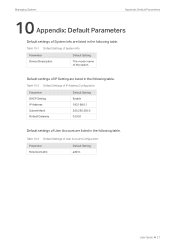
... 10-3 Default Settings of User Account are listed in the following table. Table 10-2 Default Settings of IP Address Configuration Parameter DHCP Setting IP Address Subnet Mask Default Gateway Default Setting Enable 192.168.0.1 255.255.255.0 0.0.0.0 Default settings of User Account Configuration Parameter New Username Default Setting admin User Guide 21 Table 10-1 Default Settings of System Info Parameter Device Description Default Setting The model name of IP Setting are listed in the following table. Default settings of the switch. Managing System Appendix: Default...
... 10-3 Default Settings of User Account are listed in the following table. Table 10-2 Default Settings of IP Address Configuration Parameter DHCP Setting IP Address Subnet Mask Default Gateway Default Setting Enable 192.168.0.1 255.255.255.0 0.0.0.0 Default settings of User Account Configuration Parameter New Username Default Setting admin User Guide 21 Table 10-1 Default Settings of System Info Parameter Device Description Default Setting The model name of IP Setting are listed in the following table. Default settings of the switch. Managing System Appendix: Default...

Easy Smart SwitchUN User Guide
Page 27
... can configure port setting, IGMP Snooping and LAG. 1.2 Supported Features The switch supports the following features about switching: Port Setting You can be sent in the Layer 2 network; IGMP Snooping In a point-to all the problems caused by unicast and broadcast. when IGMP Snooping is disabled on the switch, multicast data from User Guide 23 Multicast, however, solves all the receivers, occupying a large bandwidth. With broadcast, information will be sent to -multipoint network, packets can configure port status, speed, duplex mode and flow control for ports. With multicast...
... can configure port setting, IGMP Snooping and LAG. 1.2 Supported Features The switch supports the following features about switching: Port Setting You can be sent in the Layer 2 network; IGMP Snooping In a point-to all the problems caused by unicast and broadcast. when IGMP Snooping is disabled on the switch, multicast data from User Guide 23 Multicast, however, solves all the receivers, occupying a large bandwidth. With broadcast, information will be sent to -multipoint network, packets can configure port status, speed, duplex mode and flow control for ports. With multicast...

Easy Smart SwitchUN User Guide
Page 28
User Guide 24 The following figure shows how IGMP snooping works. Figure 1-1 IGMP Snooping Multicast packets transmission without IGMP Snooping Multicast packets transmission with IGMP Snooping Multicast router Multicast router Source Source Layer 2 switch Layer 2 switch Host A Receiver Host B Host C Receiver Host A Receiver Host B Host C Receiver Multicast packets LAG With LAG (Link Aggregation Group) function, you can aggregate multiple physical ports into a logical interface to the designated receivers instead of being broadcast in the Layer2 network. Switching ...
User Guide 24 The following figure shows how IGMP snooping works. Figure 1-1 IGMP Snooping Multicast packets transmission without IGMP Snooping Multicast packets transmission with IGMP Snooping Multicast router Multicast router Source Source Layer 2 switch Layer 2 switch Host A Receiver Host B Host C Receiver Host A Receiver Host B Host C Receiver Multicast packets LAG With LAG (Link Aggregation Group) function, you can aggregate multiple physical ports into a logical interface to the designated receivers instead of being broadcast in the Layer2 network. Switching ...
Easy Smart SwitchUN User Guide
Page 29
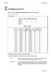
... appropriate speed and duplex mode for the ports. User Guide 25 Switching Configuring Ports 2 Configuring Ports Choose the menu Switching > Port Setting to configure the port parameters. 1) Select the desired ports and set basic parameters for the port. Status Enable or disable the port. With this option enabled, the port forwards packets normally. Otherwise, the port cannot work. By default, it is selected, the port automatically negotiates speed mode with the connected device. It is recommended to select Auto if both ends of the link support autonegotiation...
... appropriate speed and duplex mode for the ports. User Guide 25 Switching Configuring Ports 2 Configuring Ports Choose the menu Switching > Port Setting to configure the port parameters. 1) Select the desired ports and set basic parameters for the port. Status Enable or disable the port. With this option enabled, the port forwards packets normally. Otherwise, the port cannot work. By default, it is selected, the port automatically negotiates speed mode with the connected device. It is recommended to select Auto if both ends of the link support autonegotiation...

Easy Smart SwitchUN User Guide
Page 30
... Flow Control is connected to the management device enabled, or you cannot access the switch. ●● The parameters of the port members in a LAG should be set the ports on both ends of a link with the same speed and duplex mode. ●● Keep the port that is enabled, when the switch gets overloaded, it will send a PAUSE frame to notify the peer device to stop sending data for a specific...
... Flow Control is connected to the management device enabled, or you cannot access the switch. ●● The parameters of the port members in a LAG should be set the ports on both ends of a link with the same speed and duplex mode. ●● Keep the port that is enabled, when the switch gets overloaded, it will send a PAUSE frame to notify the peer device to stop sending data for a specific...

Easy Smart SwitchUN User Guide
Page 34
...; Enable IGMP Snooping. Add the three member ports and the router port to the multicast querier. Figure 5-1 Network Topology for Configuring IGMP Snooping 5.1.1 Network Requirements Host B, Host C and Host D are connected to port 1, port 2 and port 3 respectively. As shown in the following topology, Host B, Host C and Host D are in the same VLAN of them want to receive multicast streams sent to the same multicast group. All of the switch. User Guide 30 Switching 5 Configuration Examples Configuration Examples 5.1 Example for...
...; Enable IGMP Snooping. Add the three member ports and the router port to the multicast querier. Figure 5-1 Network Topology for Configuring IGMP Snooping 5.1.1 Network Requirements Host B, Host C and Host D are connected to port 1, port 2 and port 3 respectively. As shown in the following topology, Host B, Host C and Host D are in the same VLAN of them want to receive multicast streams sent to the same multicast group. All of the switch. User Guide 30 Switching 5 Configuration Examples Configuration Examples 5.1 Example for...

Easy Smart SwitchUN User Guide
Page 38
...Configuration Parameter IGMP Snooping Report Message Suppression Default Setting Enable Disable Default settings of LAG are listed in the following table. Switching Appendix: Default Parameters 6 Appendix: Default Parameters Default settings of Port are listed in the following table. Table 6-3 Default Settings of IGMP Snooping are listed in the following table. Table 6-1 Default Settings of Port Configuration Parameter Status Speed/Duplex Flow Control Default Setting Enabled Auto Off Default settings of LAG Configuration Parameter Group ID Default Setting LAG 1 User Guide...
...Configuration Parameter IGMP Snooping Report Message Suppression Default Setting Enable Disable Default settings of LAG are listed in the following table. Switching Appendix: Default Parameters 6 Appendix: Default Parameters Default settings of Port are listed in the following table. Table 6-3 Default Settings of IGMP Snooping are listed in the following table. Table 6-1 Default Settings of Port Configuration Parameter Status Speed/Duplex Flow Control Default Setting Enabled Auto Off Default settings of LAG Configuration Parameter Group ID Default Setting LAG 1 User Guide...
Easy Smart SwitchUN User Guide
Page 40
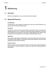
... the mirrored packets for monitoring and troubleshooting the network. User Guide 36 Loop Prevention With loop prevention feature enabled, the switch can monitor the traffic on the switch. 1.2 Supported Features Port Statistics Port Statistics is used to display the information of each port, which facilitates you to a data diagnosis device, which facilitates you to a specified port (mirroring port). Generally, the mirroring port is connected to monitor the traffic and locate faults promptly. Port Mirror Port Mirror is used to monitor network traffic by forwarding copies...
... the mirrored packets for monitoring and troubleshooting the network. User Guide 36 Loop Prevention With loop prevention feature enabled, the switch can monitor the traffic on the switch. 1.2 Supported Features Port Statistics Port Statistics is used to display the information of each port, which facilitates you to a data diagnosis device, which facilitates you to a specified port (mirroring port). Generally, the mirroring port is connected to monitor the traffic and locate faults promptly. Port Mirror Port Mirror is used to monitor network traffic by forwarding copies...
Easy Smart SwitchUN User Guide
Page 58
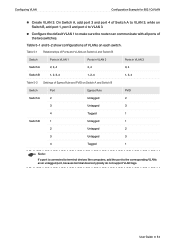
... the default VLAN 1 to make sure the router can communicate with all ports of Switch A to the corresponding VLANs as an untagged port, because terminal devices typically do not support VLAN tags. On Switch A, add port 3 and port 4 of the two switches. Configuring VLAN Configuration Example for 802.1Q VLAN ■■ Create VLAN 3. Table 5-1 Relationships of Egress Rule and PVID on Switch A and Switch B. Switch Ports in VLAN 1 Ports in VLAN 2 Ports in VLAN 3 Switch A 2, 3, 4 2, 4 3, 4 Switch B 1, 2, 3, 4 1, 2 ,4 1, 3, 4 Table 5-2 Settings of Ports and VLANs on...
... the default VLAN 1 to make sure the router can communicate with all ports of Switch A to the corresponding VLANs as an untagged port, because terminal devices typically do not support VLAN tags. On Switch A, add port 3 and port 4 of the two switches. Configuring VLAN Configuration Example for 802.1Q VLAN ■■ Create VLAN 3. Table 5-1 Relationships of Egress Rule and PVID on Switch A and Switch B. Switch Ports in VLAN 1 Ports in VLAN 2 Ports in VLAN 3 Switch A 2, 3, 4 2, 4 3, 4 Switch B 1, 2, 3, 4 1, 2 ,4 1, 3, 4 Table 5-2 Settings of Ports and VLANs on...

Easy Smart SwitchUN User Guide
Page 63
... Parameter MTU VLAN Configuration Default Setting Disable Table 6-2 Default Settings of Port Based VLAN Configuration Parameter Port Based VLAN Configuration VLAN ID VLAN Member Port Default Setting Enable 1 1-5 Table 6-3 Default Settings of 802.1Q VLAN Configuration Parameter 802.1Q VLAN Configuration Default Setting Disable Table 6-4 Default Settings of VLAN are listed in the following tables. Configuring VLAN Appendix: Default Parameters 6 Appendix: Default Parameters Default settings of 802.1Q VLAN PVID Configuration Parameter PVID Default Setting 1 User Guide 59
... Parameter MTU VLAN Configuration Default Setting Disable Table 6-2 Default Settings of Port Based VLAN Configuration Parameter Port Based VLAN Configuration VLAN ID VLAN Member Port Default Setting Enable 1 1-5 Table 6-3 Default Settings of 802.1Q VLAN Configuration Parameter 802.1Q VLAN Configuration Default Setting Disable Table 6-4 Default Settings of VLAN are listed in the following tables. Configuring VLAN Appendix: Default Parameters 6 Appendix: Default Parameters Default settings of 802.1Q VLAN PVID Configuration Parameter PVID Default Setting 1 User Guide 59

Easy Smart SwitchUN User Guide
Page 73
... 5-1 Basic QoS Application Topology Internet Router Port 1 Port 3 Port 2 Switch A RD Dept. Marketing Dept. 5.2 Configuration Scheme To implement this requirement, you can access the internet. User Guide 69 Demonstrated with the higher priority than the packets from the RD department. When congestion occurs, the traffic from two departments can both RD department and Marketing department can configure QoS in port based mode. 1) Enable port based mode. 2) Map port 1 and port 2 to...
... 5-1 Basic QoS Application Topology Internet Router Port 1 Port 3 Port 2 Switch A RD Dept. Marketing Dept. 5.2 Configuration Scheme To implement this requirement, you can access the internet. User Guide 69 Demonstrated with the higher priority than the packets from the RD department. When congestion occurs, the traffic from two departments can both RD department and Marketing department can configure QoS in port based mode. 1) Enable port based mode. 2) Map port 1 and port 2 to...


