Operating Instructions
Page 2
... by one way. In this equipment does cause harmful interference to operate this manual could void your cable service provider. Sony TV Model No. CAUTION To prevent electric shock, do not expose the screen to moisture condensation. NOTIFICATION This equipment has been tested...programming and signal provided by qualified service personnel before turning on the TV. Sony TV-Stand Model No. Availability of Sony Corporation and Sony Computer Entertainment Inc. "XMB" and "xross media bar" are not of the TV. This equipment generates, uses and can be installed near an easily ...
... by one way. In this equipment does cause harmful interference to operate this manual could void your cable service provider. Sony TV Model No. CAUTION To prevent electric shock, do not expose the screen to moisture condensation. NOTIFICATION This equipment has been tested...programming and signal provided by qualified service personnel before turning on the TV. Sony TV-Stand Model No. Availability of Sony Corporation and Sony Computer Entertainment Inc. "XMB" and "xross media bar" are not of the TV. This equipment generates, uses and can be installed near an easily ...

Operating Instructions
Page 9
...Screen Video Options Category Object Bar Media Category Bar TV From the horizontal Media Category Bar you can also be selected from the Category Object Bar for the External Inputs. ~ • This manual is for the 40 and 46 inch BRAVIA KDL-V Series models with screen size measured diagonally. 9 The XMB...™ is an easy way to access the XMB™. TV Home Menu: XMB™ (XrossMediaBar) The XMB™ is a menu of ...
...Screen Video Options Category Object Bar Media Category Bar TV From the horizontal Media Category Bar you can also be selected from the Category Object Bar for the External Inputs. ~ • This manual is for the 40 and 46 inch BRAVIA KDL-V Series models with screen size measured diagonally. 9 The XMB...™ is an easy way to access the XMB™. TV Home Menu: XMB™ (XrossMediaBar) The XMB™ is a menu of ...
Operating Instructions
Page 10
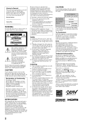
.... In this task with the securing screw (supplied) using a coin, etc. 3 Adjust the length by the Wall-Mount Bracket model for your TV is not enough, use commercial screws 1/8 to 3/16 inch (3 to 4 mm) diameter to fit to reattach the Table-Top Stand. Make sure that the wall-...mounting of the wall for withstanding the TV's weight. • For product protection and safety reasons, Sony strongly recommends that you while holding the Table-Top Stand. ~ • Be sure to take measures to remove the Table-Top...
.... In this task with the securing screw (supplied) using a coin, etc. 3 Adjust the length by the Wall-Mount Bracket model for your TV is not enough, use commercial screws 1/8 to 3/16 inch (3 to 4 mm) diameter to fit to reattach the Table-Top Stand. Make sure that the wall-...mounting of the wall for withstanding the TV's weight. • For product protection and safety reasons, Sony strongly recommends that you while holding the Table-Top Stand. ~ • Be sure to take measures to remove the Table-Top...
Operating Instructions
Page 28
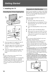
... Picture Mode Vivid For enhanced picture contrast and sharpness. Standard For standard picture settings. Most suitable for home entertainment. Your TV's specific information such as a specified volume at the specified time you made . Sets the time in a theater-like ... channel as well as Model Name, Serial Number, Software Version and downloadable ratings if available from this is displayed here. TV Setting Description Product Support Contact Sony Signal Diagnostics Sony contact information is available from the TV is executed the TV will save your convenience....
... Picture Mode Vivid For enhanced picture contrast and sharpness. Standard For standard picture settings. Most suitable for home entertainment. Your TV's specific information such as a specified volume at the specified time you made . Sets the time in a theater-like ... channel as well as Model Name, Serial Number, Software Version and downloadable ratings if available from this is displayed here. TV Setting Description Product Support Contact Sony Signal Diagnostics Sony contact information is available from the TV is executed the TV will save your convenience....
Operating Instructions
Page 42
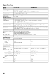
...Power and others Power requirement 120 V-240 V AC, 50/60 Hz Power consumption in use 220 W 260 W in standby All models less than 0.4 W Screen size (inches 40 46 measured diagonally) Display resolution (horizontal × vertical) Speaker 1,920 dots × 1,080 lines Full range: 42 ×...NTSC: American TV standard ATSC (8VSB terrestrial): ATSC compliant 8VSB QAM on cable: ANSI/SCTE 07 2000 (Does not include CableCARD functionality) Channel coverage Analog terrestrial: 2-69 / Digital terrestrial: 2-69 Analog Cable: 1-125 / Digital Cable: 1-135 Panel system LCD (Liquid Crystal ...
...Power and others Power requirement 120 V-240 V AC, 50/60 Hz Power consumption in use 220 W 260 W in standby All models less than 0.4 W Screen size (inches 40 46 measured diagonally) Display resolution (horizontal × vertical) Speaker 1,920 dots × 1,080 lines Full range: 42 ×...NTSC: American TV standard ATSC (8VSB terrestrial): ATSC compliant 8VSB QAM on cable: ANSI/SCTE 07 2000 (Does not include CableCARD functionality) Channel coverage Analog terrestrial: 2-69 / Digital terrestrial: 2-69 Analog Cable: 1-125 / Digital Cable: 1-135 Panel system LCD (Liquid Crystal ...
Operating Instructions
Page 43
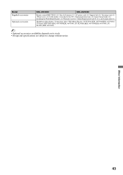
Model Supplied accessories Optional accessories KDL-40V3000 KDL-46V3000 Remote control RM-YD014 (1) / Size AA batteries (2) / AC power cord (1) / Support belt (1) / Securing screw (1) / Wood screw (1) / Cable ... (1 attached to change without notice. Other Information 43 and Canada only) (1) Headphones plug adapter / Connecting cables / Wall-Mount Bracket: SU-WL500 (KDL-40V3000/KDL-46V3000) / TV-Stand: RHT-G800 (KDL-40V3000/KDL-46V3000), SU-FL300M (KDL-40V3000/KDL-46V3000), SUFL300L (KDL-46V3000) ~ • Optional accessories availability depends on its stock. •...
Model Supplied accessories Optional accessories KDL-40V3000 KDL-46V3000 Remote control RM-YD014 (1) / Size AA batteries (2) / AC power cord (1) / Support belt (1) / Securing screw (1) / Wood screw (1) / Cable ... (1 attached to change without notice. Other Information 43 and Canada only) (1) Headphones plug adapter / Connecting cables / Wall-Mount Bracket: SU-WL500 (KDL-40V3000/KDL-46V3000) / TV-Stand: RHT-G800 (KDL-40V3000/KDL-46V3000), SU-FL300M (KDL-40V3000/KDL-46V3000), SUFL300L (KDL-46V3000) ~ • Optional accessories availability depends on its stock. •...
Service Manual
Page 1
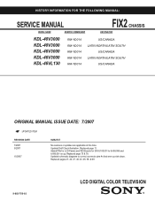
.... Updated schematic diagrams to 8,499,999 and 8,600,001 on up side down. Replaced pages 27, 34, 37, 40, 43, 45, 59, & 69. 9-883-756-03 LCD DIGITAL COLOR TELEVISION Updated Self Check illustration. Replaced page 75 & 78. Replaced page 11. HISTORY INFORMATION FOR THE FOLLOWING MANUAL...: SERVICE MANUAL FIX2 CHASSIS MODEL NAME REMOTE COMMANDER DESTINATION KDL-40V3000 KDL-40V3000 KDL-46V3000 KDL-46V3000 ...
.... Updated schematic diagrams to 8,499,999 and 8,600,001 on up side down. Replaced pages 27, 34, 37, 40, 43, 45, 59, & 69. 9-883-756-03 LCD DIGITAL COLOR TELEVISION Updated Self Check illustration. Replaced page 75 & 78. Replaced page 11. HISTORY INFORMATION FOR THE FOLLOWING MANUAL...: SERVICE MANUAL FIX2 CHASSIS MODEL NAME REMOTE COMMANDER DESTINATION KDL-40V3000 KDL-40V3000 KDL-46V3000 KDL-46V3000 ...
Service Manual
Page 3
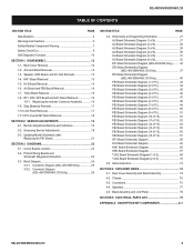
... Board Removal 18 SECTION 2: SERVICE ADJUSTMENTS 19 2-1. Updating Model Information after Replacing the FB1 Board 21 SECTION 3: DIAGRAMS... 16 1-8-1. Remote Adjustment Buttons and Indicators 19 2-2. Stay (Bracket) Removal 17 1-10.LCD Panel Removal 17 1-11. Bezel Assembly and LCD Panel 78 SECTION 5: ELECTRICAL PARTS LIST 79 APPENDIX A: ENCRYPTION KEY COMPONENTS A-1 KDL-40V3000... Board Schematic Diagram (KDL-46V3000/46VL130 Only 37 DF3 Board Schematic Diagram (KDL-46V3000/46VL130 Only 40 FB3 Board Schematic Diagram (1 of 15 43 FB3 Board Schematic Diagram (2 of 15 44 FB3...
... Board Removal 18 SECTION 2: SERVICE ADJUSTMENTS 19 2-1. Updating Model Information after Replacing the FB1 Board 21 SECTION 3: DIAGRAMS... 16 1-8-1. Remote Adjustment Buttons and Indicators 19 2-2. Stay (Bracket) Removal 17 1-10.LCD Panel Removal 17 1-11. Bezel Assembly and LCD Panel 78 SECTION 5: ELECTRICAL PARTS LIST 79 APPENDIX A: ENCRYPTION KEY COMPONENTS A-1 KDL-40V3000... Board Schematic Diagram (KDL-46V3000/46VL130 Only 37 DF3 Board Schematic Diagram (KDL-46V3000/46VL130 Only 40 FB3 Board Schematic Diagram (1 of 15 43 FB3 Board Schematic Diagram (2 of 15 44 FB3...
Service Manual
Page 8
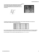
The servicing of these models have been processed using Lead Free Solder. For more information on the use Lead Free Solder material in these boards requires special precautions to be ... joints. H1 etc [ see example ]. example 1 The circuit boards used in order to guarantee optimal quality of Lead Free Solder, please refer to http://www.sony-training.com KDL-40V3000/46V3000/46VL130 8 Lead Free Solder is strongly recommended to the board designation e.g.
The servicing of these models have been processed using Lead Free Solder. For more information on the use Lead Free Solder material in these boards requires special precautions to be ... joints. H1 etc [ see example ]. example 1 The circuit boards used in order to guarantee optimal quality of Lead Free Solder, please refer to http://www.sony-training.com KDL-40V3000/46V3000/46VL130 8 Lead Free Solder is strongly recommended to the board designation e.g.

Service Manual
Page 10
...PC standby mode. * If LED blinks continuously, this may indicate that the TV needs servicing. KDL-40V3000/46V3000/46VL130 10 Control Buttons SELF-DIAGNOSTIC FUNCTION KDL-40V3000/46V3000/46VL130 Self Diagnosis Supported model PIC OFF/TIMER STANDBY POWER Description of LED Indictors LED POWER LED LED ...Type Green LED Description * Light when the TV set is on STANDBY LED Red LED * Lights up in orange...
...PC standby mode. * If LED blinks continuously, this may indicate that the TV needs servicing. KDL-40V3000/46V3000/46VL130 10 Control Buttons SELF-DIAGNOSTIC FUNCTION KDL-40V3000/46V3000/46VL130 Self Diagnosis Supported model PIC OFF/TIMER STANDBY POWER Description of LED Indictors LED POWER LED LED ...Type Green LED Description * Light when the TV set is on STANDBY LED Red LED * Lights up in orange...

Service Manual
Page 11
...40V3000/46V3000/46VL130 The units in standby mode. (Power off ). 2. A definition of last 3 events (Not used in FIX2 models) 00 00 00 00 00 01 00 00 00 00 00 00 00 00 0 indicates no error was detected 1 indicates an error was... time Contents ==== Power OVP Power Error T-CON Error Backlight Error Panel Temp Error Audio Protector Not Used in these models ==== Panel Error WDT- No error has occurred if the screen displays a "00") 1. TV POWER . This differs from accessing Service Adjustments. ☛ LED Display SELF CHECK 000 : ==== 002 : POW_OVP 003 : ...
...40V3000/46V3000/46VL130 The units in standby mode. (Power off ). 2. A definition of last 3 events (Not used in FIX2 models) 00 00 00 00 00 01 00 00 00 00 00 00 00 00 0 indicates no error was detected 1 indicates an error was... time Contents ==== Power OVP Power Error T-CON Error Backlight Error Panel Temp Error Audio Protector Not Used in these models ==== Panel Error WDT- No error has occurred if the screen displays a "00") 1. TV POWER . This differs from accessing Service Adjustments. ☛ LED Display SELF CHECK 000 : ==== 002 : POW_OVP 003 : ...
Service Manual
Page 18
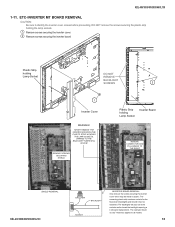
... the fluorescent backlights and should never be metal or plastic. The backlights will pop out of the sockets and/or break the backlight requiring a LCD panel replacement. REMOVE SCREWS SECURING SHIELD Plastic Strip holding Lamp Socket DO NOT REMOVE BACKLIGHT SCREWS 2 1 Inverter Cover WARNING! KDL-40V3000/46V3000/46VL130 1-11. ETC...
... the fluorescent backlights and should never be metal or plastic. The backlights will pop out of the sockets and/or break the backlight requiring a LCD panel replacement. REMOVE SCREWS SECURING SHIELD Plastic Strip holding Lamp Socket DO NOT REMOVE BACKLIGHT SCREWS 2 1 Inverter Cover WARNING! KDL-40V3000/46V3000/46VL130 1-11. ETC...

Service Manual
Page 19
... SB1.000W00AA BM0.050W00AU BD0.049A00LUW BB0.029W00AU Press JUMP CHASSIS SERVICE 000 GR 000 GRMD 0 Press JUMP SUB SERVICE 000 VERS 000 MODEL MODEL ID: XXXXXXXXXX Press JUMP BEM BOOT: MAIN: DATA: SERVICE 0. 026W00AU 0. 050W00AU 0. 049A00LUW Press JUMP KDL-40V3000/46V3000/46VL130 19...To display the service menu that contains the category you want to display the service menus. 1. REMOTE ADJUSTMENT BUTTONS AND INDICATORS DISPLAY TV POWER 5 JUMP 2-2. ACCESSING SERVICE ADJUSTMENTS To adjust various set features, use the Remote Commander to put the set into service mode...
... SB1.000W00AA BM0.050W00AU BD0.049A00LUW BB0.029W00AU Press JUMP CHASSIS SERVICE 000 GR 000 GRMD 0 Press JUMP SUB SERVICE 000 VERS 000 MODEL MODEL ID: XXXXXXXXXX Press JUMP BEM BOOT: MAIN: DATA: SERVICE 0. 026W00AU 0. 050W00AU 0. 049A00LUW Press JUMP KDL-40V3000/46V3000/46VL130 19...To display the service menu that contains the category you want to display the service menus. 1. REMOTE ADJUSTMENT BUTTONS AND INDICATORS DISPLAY TV POWER 5 JUMP 2-2. ACCESSING SERVICE ADJUSTMENTS To adjust various set features, use the Remote Commander to put the set into service mode...

Service Manual
Page 21
... Menu by pressing the following buttons on the remote commander to increase or decrease the value, do one of the following steps to reset the model information to 1 5. BEM BOOT: MAIN: DATA: SERVICE 0. 026W00AU 0. 050W00AU 0. 049A00LUW 3. Using the 3 or 6 on the Remote Commander ...BEM 0001 0001 DIFF MODEL_INFO PANEL_SIZE SERVICE 0 1 4. Volume + TV POWER . 2. To exit service mode, turn the power off. 2-3. UPDATING MODEL INFORMATION AFTER REPLACING THE FB1 BOARD Complete the following : If model size is 40" If model size is 46" Set to 0 Set to the correct size after...
... Menu by pressing the following buttons on the remote commander to increase or decrease the value, do one of the following steps to reset the model information to 1 5. BEM BOOT: MAIN: DATA: SERVICE 0. 026W00AU 0. 050W00AU 0. 049A00LUW 3. Using the 3 or 6 on the Remote Commander ...BEM 0001 0001 DIFF MODEL_INFO PANEL_SIZE SERVICE 0 1 4. Volume + TV POWER . 2. To exit service mode, turn the power off. 2-3. UPDATING MODEL INFORMATION AFTER REPLACING THE FB1 BOARD Complete the following : If model size is 40" If model size is 46" Set to 0 Set to the correct size after...
Service Manual
Page 74
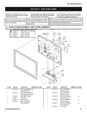
...identified by shading and ! REAR COVER ASSEMBLY AND STAND ASSEMBLY (Check the Sony Electronics Service Information website for any additional service related issues for this manual. 4-1. mark...5 3-106-918-01 3-106-917-11 2-673-535-11 3-210-944-01 DESCRIPTION [ASSEMBLY INCLUDES] REAR COVER ASSEMBLY (40) (KDL-40V3000 ONLY) REAR COVER ASSEMBLY (46) (KDL-46V3000/46VL130 ONLY) LABEL, REAR TERMINAL LABEL, HDMI SERVICE COVER...Components in the far right column of the parts list and within the dotted lines of this model.) 7-685-648-79 2-580-640-01 2-580-607-01 2-580-644-01 SCREW +...
...identified by shading and ! REAR COVER ASSEMBLY AND STAND ASSEMBLY (Check the Sony Electronics Service Information website for any additional service related issues for this manual. 4-1. mark...5 3-106-918-01 3-106-917-11 2-673-535-11 3-210-944-01 DESCRIPTION [ASSEMBLY INCLUDES] REAR COVER ASSEMBLY (40) (KDL-40V3000 ONLY) REAR COVER ASSEMBLY (46) (KDL-46V3000/46VL130 ONLY) LABEL, REAR TERMINAL LABEL, HDMI SERVICE COVER...Components in the far right column of the parts list and within the dotted lines of this model.) 7-685-648-79 2-580-640-01 2-580-607-01 2-580-644-01 SCREW +...
Service Manual
Page 75
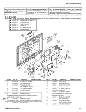
...46VL130 NOTE: The components identified by a red outline and a mark contain confidential information. CHASSIS (Check the Sony Electronics Service Information website for any additional service related issues for safety. Specific instructions must be adhered to 8,499,999 and ... TUU2 BOARD, MOUNTED 61 A-1256-154-B GF1 BOARD, COMPLETE (Use this P/N for US models only) 61 A-1361-280-A GF1 BOARD, COMPLETE (Use this P/N for all destinations, including US after consumption of this model.) 7-685-648-79 2-580-629-01 2-580-591-01 4-635-966-01 3-682-691...
...46VL130 NOTE: The components identified by a red outline and a mark contain confidential information. CHASSIS (Check the Sony Electronics Service Information website for any additional service related issues for safety. Specific instructions must be adhered to 8,499,999 and ... TUU2 BOARD, MOUNTED 61 A-1256-154-B GF1 BOARD, COMPLETE (Use this P/N for US models only) 61 A-1361-280-A GF1 BOARD, COMPLETE (Use this P/N for all destinations, including US after consumption of this model.) 7-685-648-79 2-580-629-01 2-580-591-01 4-635-966-01 3-682-691...
Service Manual
Page 76
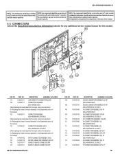
...this manual.) 104 1-910-039-02 EARTH CONNECTOR ASSEMBLY (HV2) 105 1-910-037-40 MO1929 CONNECTOR ASSEMBLY (BF) 20P 106 1-821-375-11 BOARD TO BOARD CONNECTOR 80P ...BOARD CONNECTOR 50P KDL-40V3000/46V3000/46VL130 REF. CONNECTORS (Check the Sony Electronics Service Information website for any additional service related issues for "Replacing the Inverter Connector ...contain confidential information. See Appendix A: Encryption Key Components in the Disassembly section of this model, refer to whenever these components are critical for safety. PART NO. mark are repaired and/or...
...this manual.) 104 1-910-039-02 EARTH CONNECTOR ASSEMBLY (HV2) 105 1-910-037-40 MO1929 CONNECTOR ASSEMBLY (BF) 20P 106 1-821-375-11 BOARD TO BOARD CONNECTOR 80P ...BOARD CONNECTOR 50P KDL-40V3000/46V3000/46VL130 REF. CONNECTORS (Check the Sony Electronics Service Information website for any additional service related issues for "Replacing the Inverter Connector ...contain confidential information. See Appendix A: Encryption Key Components in the Disassembly section of this model, refer to whenever these components are critical for safety. PART NO. mark are repaired and/or...
Service Manual
Page 77
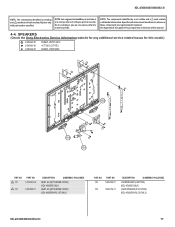
...;dential information. Replace only with part number specified. sont critiques pour la securite. See Appendix A: Encryption Key Components in the back of this model.) 2-580-640-01 2-596-649-01 2-580-606-01 SCREW, +BVTP2 4X16 +KTT 3X10 (S TYPE) SCREW, +PSW M5X8 152 152 151 REF. PART NO. ! 151... (WITH NOISE FILTER) (KDL-40V3000 ONLY) INLET, AC (WITH NOISE FILTER) (KDL-46V3000/46VL130 ONLY) REF. mark are repaired and/or replaced. SPEAKERS (Check the Sony Electronics Service Information website for any additional service related issues for safety. NO.
...;dential information. Replace only with part number specified. sont critiques pour la securite. See Appendix A: Encryption Key Components in the back of this model.) 2-580-640-01 2-596-649-01 2-580-606-01 SCREW, +BVTP2 4X16 +KTT 3X10 (S TYPE) SCREW, +PSW M5X8 152 152 151 REF. PART NO. ! 151... (WITH NOISE FILTER) (KDL-40V3000 ONLY) INLET, AC (WITH NOISE FILTER) (KDL-46V3000/46VL130 ONLY) REF. mark are repaired and/or replaced. SPEAKERS (Check the Sony Electronics Service Information website for any additional service related issues for safety. NO.
Service Manual
Page 78
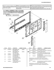
...que par une piece portant le numero specifie. BEZEL ASSEMBLY AND LCD PANEL (Check the Sony Electronics Service Information website for any additional service related issues for "Replacing... MT BOARD (LT) (KDL-46V3000/46VL130 ONLY) (When replacing the Inverter board for this model, refer to the instructions for safety. mark are repaired and/or replaced. NOTE: Les composants...1-802-488-12 DESCRIPTION [ASSEMBLY INCLUDES] BEZEL ASSEMBLY (40)H (KDL-40V3000 ONLY) BEZEL ASSEMBLY (46)H (KDL-46V3000 ONLY) GUIDE, LIGHT SENSOR SP COVER ASSEMBLY(40) (KDL-40V3000 ONLY) SP COVER ASSEMBLY(46) (...
...que par une piece portant le numero specifie. BEZEL ASSEMBLY AND LCD PANEL (Check the Sony Electronics Service Information website for any additional service related issues for "Replacing... MT BOARD (LT) (KDL-46V3000/46VL130 ONLY) (When replacing the Inverter board for this model, refer to the instructions for safety. mark are repaired and/or replaced. NOTE: Les composants...1-802-488-12 DESCRIPTION [ASSEMBLY INCLUDES] BEZEL ASSEMBLY (40)H (KDL-40V3000 ONLY) BEZEL ASSEMBLY (46)H (KDL-46V3000 ONLY) GUIDE, LIGHT SENSOR SP COVER ASSEMBLY(40) (KDL-40V3000 ONLY) SP COVER ASSEMBLY(46) (...

Service Manual
Page 116
.../46V3000/46VL130 FB3 GF1 REF. C6006 ! GF1 DESCRIPTION VALUES A-1256-154-B GF1 BOARD, COMPLETE (Use this P/N for safety. C6011 ! NO. mark are critical for US models only) 2-580-592-01 SCREW, +PSW M3X8 ! Ne les remplacer que par une piece portant le numero specifie. C6007 ! C6010 ! NOTE: The components identi...
.../46V3000/46VL130 FB3 GF1 REF. C6006 ! GF1 DESCRIPTION VALUES A-1256-154-B GF1 BOARD, COMPLETE (Use this P/N for safety. C6011 ! NO. mark are critical for US models only) 2-580-592-01 SCREW, +PSW M3X8 ! Ne les remplacer que par une piece portant le numero specifie. C6007 ! C6010 ! NOTE: The components identi...


