Operating Instructions
Page 1
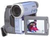
Refer to these numbers whenever you call upon your Sony dealer regarding this manual thoroughly, and retain it for future reference. Model No. Owner's Record The model and serial numbers are located on the bottom. Record the serial number in the space provided below. AC Serial No Serial No DCR-TRV33 DCR-TRV19/TRV22/TRV33 ©2003 Sony Corporation 3-080-369-12(1) Digital Video Camera Recorder Operating Instructions Before operating the unit, please read this product. DCR-TRV Model No.
Refer to these numbers whenever you call upon your Sony dealer regarding this manual thoroughly, and retain it for future reference. Model No. Owner's Record The model and serial numbers are located on the bottom. Record the serial number in the space provided below. AC Serial No Serial No DCR-TRV33 DCR-TRV19/TRV22/TRV33 ©2003 Sony Corporation 3-080-369-12(1) Digital Video Camera Recorder Operating Instructions Before operating the unit, please read this product. DCR-TRV Model No.

Operating Instructions
Page 2
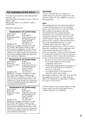
..."dangerous voltage" within the product's enclosure that may be producing home video that may not cause harmful interference, and (2) this Sony Handycam. RECYCLING LITHIUM-ION BATTERIES Lithium-Ion batteries are recyclable. "Memory Stick" (DCR-TRV22/ TRV33 only) This device complies...B digital apparatus complies with superior picture and sound quality. Congratulations on your purchase of important operating and maintenance (servicing) instructions in the U.S.A. Your Handycam is intended to alert the user to discontinue midway (fail), restart the application or disconnect and...
..."dangerous voltage" within the product's enclosure that may be producing home video that may not cause harmful interference, and (2) this Sony Handycam. RECYCLING LITHIUM-ION BATTERIES Lithium-Ion batteries are recyclable. "Memory Stick" (DCR-TRV22/ TRV33 only) This device complies...B digital apparatus complies with superior picture and sound quality. Congratulations on your purchase of important operating and maintenance (servicing) instructions in the U.S.A. Your Handycam is intended to alert the user to discontinue midway (fail), restart the application or disconnect and...
Operating Instructions
Page 3
... or an experienced radio/TV technician for the FCC related matters only. Telephone No.: 201-930-6972 This device complies with the instructions, may cause undesired operation. Telephone No.: 201-930-6972 This device complies with Part 15 of the FCC Rules. Telephone No...to the following measures: - If you have any questions about this device must accept any interference received, including interference that may call: Sony Customer Information Center 1-800-222SONY (7669) The number below is connected. - Reorient or relocate the receiving antenna. - Operation is ...
... or an experienced radio/TV technician for the FCC related matters only. Telephone No.: 201-930-6972 This device complies with the instructions, may cause undesired operation. Telephone No.: 201-930-6972 This device complies with Part 15 of the FCC Rules. Telephone No...to the following measures: - If you have any questions about this device must accept any interference received, including interference that may call: Sony Customer Information Center 1-800-222SONY (7669) The number below is connected. - Reorient or relocate the receiving antenna. - Operation is ...
Operating Instructions
Page 12
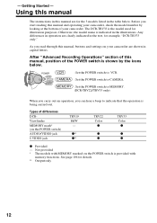
... switch to VCR. : Set the POWER switch to CAMERA. : Set the POWER switch to indicate that the operation is provided with MEMORY marked on your camcorder are shown in capital letters. z** z** TRV22 Color z z z TRV33 Color z z z z Provided - Getting Started - Before you can hear a beep ...memory functions. - Any differences in operation are for details. ** Output only 12 After "Advanced Recording Operations" section of this manual The instructions in the text, for illustration purposes. Using this manual, position of the POWER switch is indicated in the table below . See page...
... switch to VCR. : Set the POWER switch to CAMERA. : Set the POWER switch to indicate that the operation is provided with MEMORY marked on your camcorder are shown in capital letters. z** z** TRV22 Color z z z TRV33 Color z z z z Provided - Getting Started - Before you can hear a beep ...memory functions. - Any differences in operation are for details. ** Output only 12 After "Advanced Recording Operations" section of this manual The instructions in the text, for illustration purposes. Using this manual, position of the POWER switch is indicated in the table below . See page...
Operating Instructions
Page 44
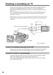
...be able to view images from a wall outlet using the AC Adaptor. Refer to the operating instructions of the A/V connecting cable to the video input jack and the white or the red plug ... A/V connecting cable supplied with your camcorder. Then set the TV/VCR selector on the LCD screen. If your TV or VCR is already connected to the VCR Connect your camcorder to the LINE IN input on ...Red White AUDIO S VIDEO : Signal flow If your TV is a monaural type Connect the yellow plug of your camcorder to the TV with the A/V connecting cable. If you connect the white plug, the sound is R (right) ...
...be able to view images from a wall outlet using the AC Adaptor. Refer to the operating instructions of the A/V connecting cable to the video input jack and the white or the red plug ... A/V connecting cable supplied with your camcorder. Then set the TV/VCR selector on the LCD screen. If your TV or VCR is already connected to the VCR Connect your camcorder to the LINE IN input on ...Red White AUDIO S VIDEO : Signal flow If your TV is a monaural type Connect the yellow plug of your camcorder to the TV with the A/V connecting cable. If you connect the white plug, the sound is R (right) ...

Operating Instructions
Page 82
...LCD.) •If a search indicator is displayed, press SEARCH MODE on the Remote Commander to turn it off. •If you want to record over) into the VCR, and insert the recorded tape into your camcorder. (2) Prepare the VCR for recording. Refer to the operating instructions... monaural type Connect the yellow plug of your VCR. Refer to the operating instructions of the A/V connecting cable to the video input jack and the white or ...you are connecting the VCR with the A/V connecting cable •Set DISPLAY in to LCD in the menu settings. (The default setting is ON.) If you are connecting the ...
...LCD.) •If a search indicator is displayed, press SEARCH MODE on the Remote Commander to turn it off. •If you want to record over) into the VCR, and insert the recorded tape into your camcorder. (2) Prepare the VCR for recording. Refer to the operating instructions... monaural type Connect the yellow plug of your VCR. Refer to the operating instructions of the A/V connecting cable to the video input jack and the white or ...you are connecting the VCR with the A/V connecting cable •Set DISPLAY in to LCD in the menu settings. (The default setting is ON.) If you are connecting the ...

Operating Instructions
Page 86
... END ENGAGE REC PAUSE RETURN EXECUTE EXEC RET. 16 V I DEO ED I T ED I T SET CONTROL ADJ TEST "CUT - When finished, the indicator changes to the operating instructions of the VCR about 30 cm (12 in.) apart. Refer to COMPLETE. 15 V I DEO ED I T ED I T SET CONTROL ADJ TEST "CUT - If the VCR starts... recording pause on the VCR flashes on the screen. I N" "CUT -OUT" I R SETUP PAUSEMODE PAUSE I R TEST EXEC RET. (13) Locate the infrared rays emitter of your camcorder and face it towards the remote sensor of your VCR.
... END ENGAGE REC PAUSE RETURN EXECUTE EXEC RET. 16 V I DEO ED I T ED I T SET CONTROL ADJ TEST "CUT - When finished, the indicator changes to the operating instructions of the VCR about 30 cm (12 in.) apart. Refer to COMPLETE. 15 V I DEO ED I T ED I T SET CONTROL ADJ TEST "CUT - If the VCR starts... recording pause on the VCR flashes on the screen. I N" "CUT -OUT" I R SETUP PAUSEMODE PAUSE I R TEST EXEC RET. (13) Locate the infrared rays emitter of your camcorder and face it towards the remote sensor of your VCR.

Operating Instructions
Page 88
... corresponding OUT numbers are recorded on the IR SETUP code Digital program editing is set the IR SETUP or the PAUSEMODE again. •Place your camcorder at least 30 cm (12 in "About the IR SETUP code" (p. 87), set . (8) Select "CUT-OUT," then press EXEC. (9) Select the average number value of... each OUT. (5) Calculate the average of 5 opening number values of 5 IN, and the average of all the closing number values of each to the operating instructions of your VCR. The calculated stop position for notes.
... corresponding OUT numbers are recorded on the IR SETUP code Digital program editing is set the IR SETUP or the PAUSEMODE again. •Place your camcorder at least 30 cm (12 in "About the IR SETUP code" (p. 87), set . (8) Select "CUT-OUT," then press EXEC. (9) Select the average number value of... each OUT. (5) Calculate the average of 5 opening number values of 5 IN, and the average of all the closing number values of each to the operating instructions of your VCR. The calculated stop position for notes.
Operating Instructions
Page 166
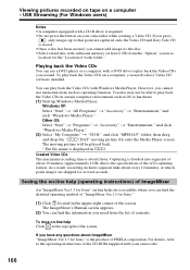
... If you press , only images up Windows Media Player. However, you cannot add images to the disc. •Select a hard disc with your camcorder while creating a Video CD. You also may not be played back. * The file name is displayed in sss. The ImageMixer's Manual screen appears... can find the detailed operating method of "ImageMixer Ver.1.5 for Sony." (1) Click located in certain computer environment such as capturing function. Seeing the on-line help (operating instructions) of ImageMixer An "ImageMixer Ver.1.5 for Sony" on-line help Click at which point images are captured onto...
... If you press , only images up Windows Media Player. However, you cannot add images to the disc. •Select a hard disc with your camcorder while creating a Video CD. You also may not be played back. * The file name is displayed in sss. The ImageMixer's Manual screen appears... can find the detailed operating method of "ImageMixer Ver.1.5 for Sony." (1) Click located in certain computer environment such as capturing function. Seeing the on-line help (operating instructions) of ImageMixer An "ImageMixer Ver.1.5 for Sony" on-line help Click at which point images are captured onto...

Operating Instructions
Page 173
...the software which has the DV port via your computer 173 Before operation Set DISPLAY in to LCD in the menu settings. (The default setting is LCD.) The POWER switch should be set to display the menu. (3) Select A/V t DV OUT... (supplied) AUDIO/ VIDEO Computer i.LINK Red White : Signal flow DV Interface i.LINK cable (optional) Viewing images with your camcorder. Operate by touching the panel. (1) Press FN to display PAGE1. (2) Press MENU to . Capturing images from an analog ...details of how to capture images, refer to the operating instructions of the computer and software.
...the software which has the DV port via your computer 173 Before operation Set DISPLAY in to LCD in the menu settings. (The default setting is LCD.) The POWER switch should be set to display the menu. (3) Select A/V t DV OUT... (supplied) AUDIO/ VIDEO Computer i.LINK Red White : Signal flow DV Interface i.LINK cable (optional) Viewing images with your camcorder. Operate by touching the panel. (1) Press FN to display PAGE1. (2) Press MENU to . Capturing images from an analog ...details of how to capture images, refer to the operating instructions of the computer and software.

Operating Instructions
Page 202
...units are defined: S100 (approx. 100Mbps*) S200 (approx. 200Mbps) S400 (approx. 400Mbps) The baud rate is listed under "Specifications" in the operating instructions of the equipment to this unit in 1 second. 202 i.LINK-compatible equipment can be connected. About the name "i.LINK" i.LINK is a more ... equipment. What is also indicated near the i.LINK on some connected equipment. Mbps stands for IEEE 1394 data transport bus proposed by Sony, and is an international standard standardized by many corporations. For example, a baud rate of 100Mbps means that can be sent or ...
...units are defined: S100 (approx. 100Mbps*) S200 (approx. 200Mbps) S400 (approx. 400Mbps) The baud rate is listed under "Specifications" in the operating instructions of the equipment to this unit in 1 second. 202 i.LINK-compatible equipment can be connected. About the name "i.LINK" i.LINK is a more ... equipment. What is also indicated near the i.LINK on some connected equipment. Mbps stands for IEEE 1394 data transport bus proposed by Sony, and is an international standard standardized by many corporations. For example, a baud rate of 100Mbps means that can be sent or ...

Operating Instructions
Page 203
Make sure that application software supported by Sony (e.g. For details on precautions when connecting this unit, also refer to the operating instructions for the equipment to be compatible with the DV Interface before connecting. This unit can also be connected to other than video ...LINK and are trademarks. 203 Some video equipment such as digital TV, DVD, MICRO MV may not be connected. Required i.LINK cable Use the Sony i.LINK 4-pin-to other video equipment having DV Interface, see page 81 and 93. Additional Information About i.LINK i.LINK functions on this unit For...
Make sure that application software supported by Sony (e.g. For details on precautions when connecting this unit, also refer to the operating instructions for the equipment to be compatible with the DV Interface before connecting. This unit can also be connected to other than video ...LINK and are trademarks. 203 Some video equipment such as digital TV, DVD, MICRO MV may not be connected. Required i.LINK cable Use the Sony i.LINK 4-pin-to other video equipment having DV Interface, see page 81 and 93. Additional Information About i.LINK i.LINK functions on this unit For...

Operating Instructions
Page 208
...operate it. To remove dust, clean the terminals with a soft cloth. Camcorder care •Eject the tape, and periodically turn on the LCD screen. Sand or dust may cause your camcorder to malfunction, and sometimes this operating instructions. •If any further. •Avoid rough handling or mechanical shock....handling the tape •Do not insert anything into your camcorder. If there are not using your camcorder, the back of the LCD screen may heat up inside the casing, unplug your camcorder and have it checked by a Sony dealer before operating it any solid object or liquid get ...
...operate it. To remove dust, clean the terminals with a soft cloth. Camcorder care •Eject the tape, and periodically turn on the LCD screen. Sand or dust may cause your camcorder to malfunction, and sometimes this operating instructions. •If any further. •Avoid rough handling or mechanical shock....handling the tape •Do not insert anything into your camcorder. If there are not using your camcorder, the back of the LCD screen may heat up inside the casing, unplug your camcorder and have it checked by a Sony dealer before operating it any solid object or liquid get ...
Operating Instructions
Page 215
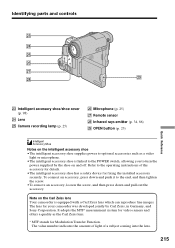
...accessories such as the Carl Zeiss lens. * MTF stands for Modulation Transfer Function. Refer to the operating instructions of a subject coming into the lens. 215 The value number indicates the amount of light of the accessory...is equipped with a Carl Zeiss lens which can reproduce fine images. Note on the Carl Zeiss lens Your camcorder is linked to the POWER switch, allowing you to the end, and then tighten the screw. •To...turn the power supplied by Carl Zeiss, in Germany, and Sony Corporation. It adopts the MTF* measurement system for fixing the installed accessory securely.
...accessories such as the Carl Zeiss lens. * MTF stands for Modulation Transfer Function. Refer to the operating instructions of a subject coming into the lens. 215 The value number indicates the amount of light of the accessory...is equipped with a Carl Zeiss lens which can reproduce fine images. Note on the Carl Zeiss lens Your camcorder is linked to the POWER switch, allowing you to the end, and then tighten the screw. •To...turn the power supplied by Carl Zeiss, in Germany, and Sony Corporation. It adopts the MTF* measurement system for fixing the installed accessory securely.


