
Operating Instructions
Page 2
... superior picture and sound quality. If you have any interference received, including interference that you can capture life's precious moments with Part 15 of uninsulated "dangerous voltage" within the product's enclosure that may call toll free 1-800-8228837, or visit http://www...to alert the user to the presence of the FCC Rules. Your Handycam is for years to use. For more information regarding recycling of Conformity Trade Name: SONY Model No.: DCR-DVD101 Responsible Party:Sony Electronics Inc. Address: 16450 W. Congratulations on your used rechargeable batteries to...
... superior picture and sound quality. If you have any interference received, including interference that you can capture life's precious moments with Part 15 of uninsulated "dangerous voltage" within the product's enclosure that may call toll free 1-800-8228837, or visit http://www...to alert the user to the presence of the FCC Rules. Your Handycam is for years to use. For more information regarding recycling of Conformity Trade Name: SONY Model No.: DCR-DVD101 Responsible Party:Sony Electronics Inc. Address: 16450 W. Congratulations on your used rechargeable batteries to...
Operating Instructions
Page 3
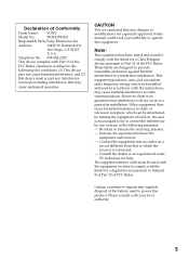
...reception, which the receiver is encouraged to try to correct the interference by one or more of Conformity Trade Name: SONY Model No.: DCR-DVD201 Responsible Party:Sony Electronics Inc. Reorient or relocate the receiving antenna. - Operation is no guarantee that interference will not occur in ... with the instructions, may cause undesired operation. CAUTION You are designed to provide reasonable protection against harmful interference in order to Part 15 of the FCC Rules. This equipment generates, uses, and can be used to the following measures: - Consult the ...
...reception, which the receiver is encouraged to try to correct the interference by one or more of Conformity Trade Name: SONY Model No.: DCR-DVD201 Responsible Party:Sony Electronics Inc. Reorient or relocate the receiving antenna. - Operation is no guarantee that interference will not occur in ... with the instructions, may cause undesired operation. CAUTION You are designed to provide reasonable protection against harmful interference in order to Part 15 of the FCC Rules. This equipment generates, uses, and can be used to the following measures: - Consult the ...
Operating Instructions
Page 11
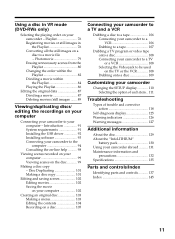
...Recording on a disc 105 Connecting your camcorder to a TV and a VCR Dubbing a disc to a tape 106 Connecting your camcorder to a VCR 106 Dubbing to ...a tape 107 Dubbing a TV program or video tape onto a disc 108 Connecting your camcorder to a TV ... recorded on your camcorder abroad .......... 131 Maintenance information and precautions 132 Specifications 135 Parts and controls/Index Identifying parts and controls 137... the recordings on your computer Connecting your camcorder to a movie file - Getting Started Using a disc in the ...
...Recording on a disc 105 Connecting your camcorder to a TV and a VCR Dubbing a disc to a tape 106 Connecting your camcorder to a VCR 106 Dubbing to ...a tape 107 Dubbing a TV program or video tape onto a disc 108 Connecting your camcorder to a TV ... recorded on your camcorder abroad .......... 131 Maintenance information and precautions 132 Specifications 135 Parts and controls/Index Identifying parts and controls 137... the recordings on your computer Connecting your camcorder to a movie file - Getting Started Using a disc in the ...
Operating Instructions
Page 16
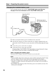
... from coming into contact with this unit while using the AC adaptor, disconnect the plug from the DC IN jack on your camcorder. If any trouble occurs with the metal parts of the DC plug of the AC adaptor. This may flash if the battery pack is not installed correctly or the... completed (full charge). See page 130 for more information on the "InfoLITHIUM" battery pack. Step 1 Preparing the power source Charging the installed battery pack Your camcorder operates only with the plug's v mark facing up 2 1 1 Make sure that the battery pack is installed on the...
... from coming into contact with this unit while using the AC adaptor, disconnect the plug from the DC IN jack on your camcorder. If any trouble occurs with the metal parts of the DC plug of the AC adaptor. This may flash if the battery pack is not installed correctly or the... completed (full charge). See page 130 for more information on the "InfoLITHIUM" battery pack. Step 1 Preparing the power source Charging the installed battery pack Your camcorder operates only with the plug's v mark facing up 2 1 1 Make sure that the battery pack is installed on the...
Operating Instructions
Page 134
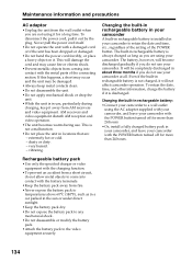
...function. •To prevent an accident from a short circuit, do not allow metal objects to the video equipment securely. The built-in use your camcorder to temperatures above 60°C (140°F), such as you are : - The battery, however, will damage the cord and may be completely.... •While the unit is in rechargeable battery is installed in locations that are using the AC adaptor supplied with your camcorder, and leave your camcorder with the metal parts of the POWER button. very humid. - Never pull the power cord itself. •Do not operate the unit with ...
...function. •To prevent an accident from a short circuit, do not allow metal objects to the video equipment securely. The built-in use your camcorder to temperatures above 60°C (140°F), such as you are : - The battery, however, will damage the cord and may be completely.... •While the unit is in rechargeable battery is installed in locations that are using the AC adaptor supplied with your camcorder, and leave your camcorder with the metal parts of the POWER button. very humid. - Never pull the power cord itself. •Do not operate the unit with ...
Operating Instructions
Page 136
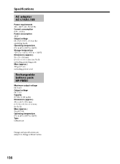
...°F) Storage temperature -20°C to + 60°C (-4°F to + 140°F) Dimensions (approx.) 56 × 31 × 100 mm (2 1/4 × 1 1/4 × 4 in.) (w/h/d) excluding projecting parts Mass (approx.) 190 g (6.7 oz) excluding power cord Rechargeable battery pack NP-FM50 Maximum output voltage DC 8.4 V Output voltage DC 7.2 V Capacity 8.5 Wh (1 180 mAh) Dimensions (approx...
...°F) Storage temperature -20°C to + 60°C (-4°F to + 140°F) Dimensions (approx.) 56 × 31 × 100 mm (2 1/4 × 1 1/4 × 4 in.) (w/h/d) excluding projecting parts Mass (approx.) 190 g (6.7 oz) excluding power cord Rechargeable battery pack NP-FM50 Maximum output voltage DC 8.4 V Output voltage DC 7.2 V Capacity 8.5 Wh (1 180 mAh) Dimensions (approx...
Operating Instructions
Page 137
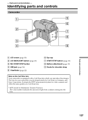
.... * MTF stands for shoulder strap Note on the Carl Zeiss lens Your camcorder is equipped with a Carl Zeiss lens which can reproduce fine images. Identifying parts and controls Camcorder 1 5 6 2 7 8 3 4 9 1 LCD screen (page 20...) 2 LCD BACKLIGHT button (page 20) 3 REC START/STOP button 4 USB jack (page 94) 5 Viewfinder (page 22) 6 Eye cup 7 START/STOP button (page 30) 8 Battery attachment (page 15) 9 Hooks for Modulation Transfer Function. - The lens for your camcorder was developed jointly by Carl Zeiss, in Germany, and Sony...
.... * MTF stands for shoulder strap Note on the Carl Zeiss lens Your camcorder is equipped with a Carl Zeiss lens which can reproduce fine images. Identifying parts and controls Camcorder 1 5 6 2 7 8 3 4 9 1 LCD screen (page 20...) 2 LCD BACKLIGHT button (page 20) 3 REC START/STOP button 4 USB jack (page 94) 5 Viewfinder (page 22) 6 Eye cup 7 START/STOP button (page 30) 8 Battery attachment (page 15) 9 Hooks for Modulation Transfer Function. - The lens for your camcorder was developed jointly by Carl Zeiss, in Germany, and Sony...

Operating Instructions
Page 138
Otherwise, you cannot attach the tripod securely, and the screw may damage your camcorder. 138 qh qa qs qj qd qf qg qk q; Identifying parts and controls q; Mode dial (page 19) qa POWER/CHG lamp (page 16) qs REMOTE jack Use to connect to optional accessories. qd Viewfinder lens adjustment dial (page 22) qf POWER button (page 19) qg BATT (battery) release button (page 15) qh DC IN jack (page 16) qj Lens cap (page 28) qk Tripod receptacle Make sure that the length of the tripod screw is less than 5.5 mm (7/32 inch).
Otherwise, you cannot attach the tripod securely, and the screw may damage your camcorder. 138 qh qa qs qj qd qf qg qk q; Identifying parts and controls q; Mode dial (page 19) qa POWER/CHG lamp (page 16) qs REMOTE jack Use to connect to optional accessories. qd Viewfinder lens adjustment dial (page 22) qf POWER button (page 19) qg BATT (battery) release button (page 15) qh DC IN jack (page 16) qj Lens cap (page 28) qk Tripod receptacle Make sure that the length of the tripod screw is less than 5.5 mm (7/32 inch).

Operating Instructions
Page 139
... out the accessory. 139 Refer to optional accessories such as a microphone. •The intelligent accessory shoe is preferred for fixing the installed accessory securely. Identifying parts and controls ql wh w; This jack also accepts a "plug-in-power" microphone. wj wk wa ws wl wd wf wg...
... out the accessory. 139 Refer to optional accessories such as a microphone. •The intelligent accessory shoe is preferred for fixing the installed accessory securely. Identifying parts and controls ql wh w; This jack also accepts a "plug-in-power" microphone. wj wk wa ws wl wd wf wg...
Operating Instructions
Page 140
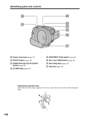
Power zoom lever (page 33) ea PHOTO button (page 35) es SUPER NS PLUS/COLOR SLOW S button (page 45) ed ACCESS lamp (page 26) ef NIGHTSHOT PLUS switch (page 45) eg Disc cover OPEN switch (page 26) eh Recording lamp (page 29) ej Grip belt (page 28) Attaching the shoulder strap Attach the shoulder strap supplied with your camcorder to the hooks for the shoulder strap. 4 1 3 2 140 Identifying parts and controls e; es ea ed ef eg eh ej e;
Power zoom lever (page 33) ea PHOTO button (page 35) es SUPER NS PLUS/COLOR SLOW S button (page 45) ed ACCESS lamp (page 26) ef NIGHTSHOT PLUS switch (page 45) eg Disc cover OPEN switch (page 26) eh Recording lamp (page 29) ej Grip belt (page 28) Attaching the shoulder strap Attach the shoulder strap supplied with your camcorder to the hooks for the shoulder strap. 4 1 3 2 140 Identifying parts and controls e; es ea ed ef eg eh ej e;
Operating Instructions
Page 142
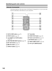
Identifying parts and controls Remote Commander The buttons that have the same name on the Remote Commander as on your camcorder function identically to the buttons on your camcorder. 1 8 2 3 9 4 q; 5 qa 6 qs 7 qd 1 DATA CODE button (page 59) 2 PHOTO button (page 35) 3 SCAN/ (page 58) SLOW buttons 4 . PREV/> NEXT buttons (page 58) 5 N PLAY button (page...
Identifying parts and controls Remote Commander The buttons that have the same name on the Remote Commander as on your camcorder function identically to the buttons on your camcorder. 1 8 2 3 9 4 q; 5 qa 6 qs 7 qd 1 DATA CODE button (page 59) 2 PHOTO button (page 35) 3 SCAN/ (page 58) SLOW buttons 4 . PREV/> NEXT buttons (page 58) 5 N PLAY button (page...
Operating Instructions
Page 143
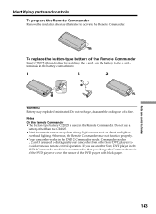
... Commander may explode if mistreated. If you use a battery other than the CR2025. •Point the remote sensor away from other Sony DVD players to avoid erroneous remote control operation. on the battery to activate the Remote Commander. Commander modes 1, 2 and 3 are used...camcorder from strong light sources such as illustrated to the + and - Notes On the Remote Commander •The button-type battery CR2025 is recommended that you change the Commander mode of the DVD player or cover the sensor of the DVD player with black paper. terminals in the Remote Commander. Parts...
... Commander may explode if mistreated. If you use a battery other than the CR2025. •Point the remote sensor away from other Sony DVD players to avoid erroneous remote control operation. on the battery to activate the Remote Commander. Commander modes 1, 2 and 3 are used...camcorder from strong light sources such as illustrated to the + and - Notes On the Remote Commander •The button-type battery CR2025 is recommended that you change the Commander mode of the DVD player or cover the sensor of the DVD player with black paper. terminals in the Remote Commander. Parts...
Operating Instructions
Page 144
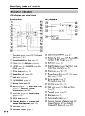
Identifying parts and controls Operation indicators LCD display and viewfinder On shooting On playback wa ws 0001 wd wf AUTO 60 AWB F1.8 9dB N 0:12:34 -R VIDEO ...
Identifying parts and controls Operation indicators LCD display and viewfinder On shooting On playback wa ws 0001 wd wf AUTO 60 AWB F1.8 9dB N 0:12:34 -R VIDEO ...
Operating Instructions
Page 145
... Daylight saving time ...... 24, 116 DEMO 115 Digital effect 54 Digital zoom 33 Disc dubbing 106 Disc title 67 Disc 6 DISPLAY 59 Divide 84, 87 DVD-R 6 DVD-RW 6 E EXP BRKTG 41 EXPOSURE 43 F, G, H FADER 53 Fade in/out 53 Finalize 64 FINE 38 Flash 111 Folder 71 FOCUS 52 Format 74 ...Visual Index 56 VR mode 7 W, X, Y, Z Warning indicators 126 Warning messages 127 White balance 50 Wide-angle 33 Wide mode 48 WIPE 53 Zoom 33, 61 Parts and controls/Index 145 See Beep OVERLAP 53 PASTEL 54 PB ZOOM 61 Photomovie 65, 79 Picture effect 54 Playback pause 58 Playing time 17...
... Daylight saving time ...... 24, 116 DEMO 115 Digital effect 54 Digital zoom 33 Disc dubbing 106 Disc title 67 Disc 6 DISPLAY 59 Divide 84, 87 DVD-R 6 DVD-RW 6 E EXP BRKTG 41 EXPOSURE 43 F, G, H FADER 53 Fade in/out 53 Finalize 64 FINE 38 Flash 111 Folder 71 FOCUS 52 Format 74 ...Visual Index 56 VR mode 7 W, X, Y, Z Warning indicators 126 Warning messages 127 White balance 50 Wide-angle 33 Wide mode 48 WIPE 53 Zoom 33, 61 Parts and controls/Index 145 See Beep OVERLAP 53 PASTEL 54 PB ZOOM 61 Photomovie 65, 79 Picture effect 54 Playback pause 58 Playing time 17...

Operating Instructions
Page 147
147 Parts and controls/Index
147 Parts and controls/Index


