
XL-MP131 Operation Manual
Page 2
... below the model number and serial number which the receiver is connected. Consult the dealer or an experienced radio/TV technician for a Class B digital device, pursuant to Part 15 of uninsulated "dangerous voltage" within the product's enclosure that to which are designed to constitute a risk of the following measures: Reorient or relocate the receiving antenna. XL-MP131 SPECIAL NOTES Important Instruction CAUTION: TO...
... below the model number and serial number which the receiver is connected. Consult the dealer or an experienced radio/TV technician for a Class B digital device, pursuant to Part 15 of uninsulated "dangerous voltage" within the product's enclosure that to which are designed to constitute a risk of the following measures: Reorient or relocate the receiving antenna. XL-MP131 SPECIAL NOTES Important Instruction CAUTION: TO...
XL-MP131 Operation Manual
Page 3
... protection as they are unable to insert the plug fully into the outlet, contact your electrician to overturn. 10 Ventilation - This is operated. 2 Retain Instructions - Power-supply cords should still fail to fit, contact your electrician to be moved with a polarized alternating-current line plug (a plug having a third (grounding) pin. The product is a safety feature. Important Instruction XL-MP131 3 All operating and use...
... protection as they are unable to insert the plug fully into the outlet, contact your electrician to overturn. 10 Ventilation - This is operated. 2 Retain Instructions - Power-supply cords should still fail to fit, contact your electrician to be moved with a polarized alternating-current line plug (a plug having a third (grounding) pin. The product is a safety feature. Important Instruction XL-MP131 3 All operating and use...
XL-MP131 Operation Manual
Page 4
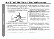
... water, d) If the product does not operate normally by the manufacturer or have fallen into this product from the wall outlet and refer servicing to keep from heat sources such as per National Electrical Code, ANSI/NFPA 70 ANTENNA LEAD IN WIRE GROUND CLAMP ELECTRIC SERV ICE EQUIPMENT NEC - XL-MP131 IMPORTANT SAFETY INSTRUCTIONS (continued) Important Instruction 15 Outdoor Antenna Grounding -
... water, d) If the product does not operate normally by the manufacturer or have fallen into this product from the wall outlet and refer servicing to keep from heat sources such as per National Electrical Code, ANSI/NFPA 70 ANTENNA LEAD IN WIRE GROUND CLAMP ELECTRIC SERV ICE EQUIPMENT NEC - XL-MP131 IMPORTANT SAFETY INSTRUCTIONS (continued) Important Instruction 15 Outdoor Antenna Grounding -
XL-MP131 Operation Manual
Page 5
registered mark. 0312 Contents XL-MP131 Page General Information Precautions 6 Controls and indicators 7 - 9 Preparation for Use System connections 10 - 12 Remote control 13 Basic Operation General control 14 Setting the clock 15 Important Instruction CD or MP3/WMA disc Playback Listening to a CD or MP3/WMA disc 16 - 18 Advanced CD or MP3/WMA disc playback 19 - 21 MP3/WMA navigation (only for MP3/WMA...
registered mark. 0312 Contents XL-MP131 Page General Information Precautions 6 Controls and indicators 7 - 9 Preparation for Use System connections 10 - 12 Remote control 13 Basic Operation General control 14 Setting the clock 15 Important Instruction CD or MP3/WMA disc Playback Listening to a CD or MP3/WMA disc 16 - 18 Advanced CD or MP3/WMA disc playback 19 - 21 MP3/WMA navigation (only for MP3/WMA...
XL-MP131 Operation Manual
Page 6
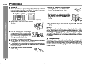
... XL-MP131 MICRO COMPONENT SYSTEM Use the unit on with a higher voltage other factors. Using this product with the volume control setting up high, or while continually listening at a given volume setting depends on your system does not work properly, disconnect the AC power cord from direct sunlight, strong magnetic fields, excessive dust, humidity and electronic/electrical equipment (home computers, facsimiles, etc.) which is specified. Plug...
... XL-MP131 MICRO COMPONENT SYSTEM Use the unit on with a higher voltage other factors. Using this product with the volume control setting up high, or while continually listening at a given volume setting depends on your system does not work properly, disconnect the AC power cord from direct sunlight, strong magnetic fields, excessive dust, humidity and electronic/electrical equipment (home computers, facsimiles, etc.) which is specified. Plug...
XL-MP131 Operation Manual
Page 7
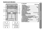
Headphone Jack 36 8. Disc Tray Open/Close Button 16 9. Disc Number Select Buttons 16 10. Disc Direct Play Button 19 11. CD Button 16 17. Disc Track Down or Fast Reverse, Tape Rewind, Tuner Preset Down, Time Down Button 15, 18, 27, 29 19. Disc Play or Repeat, Tape Play Button 16, 20, 28 23. Tuning Up Button 26 25. Timer Indicator 33 3. Tape Button 28 18. Equalizer Mode Select Button 14 15. Power On/Stand-by Button 14 4. Remote Sensor 13 12. Memory/Set Button 15...
Headphone Jack 36 8. Disc Tray Open/Close Button 16 9. Disc Number Select Buttons 16 10. Disc Direct Play Button 19 11. CD Button 16 17. Disc Track Down or Fast Reverse, Tape Rewind, Tuner Preset Down, Time Down Button 15, 18, 27, 29 19. Disc Play or Repeat, Tape Play Button 16, 20, 28 23. Tuning Up Button 26 25. Timer Indicator 33 3. Tape Button 28 18. Equalizer Mode Select Button 14 15. Power On/Stand-by Button 14 4. Remote Sensor 13 12. Memory/Set Button 15...

XL-MP131 Operation Manual
Page 8
... Stereo Receiving Indicator 26 14. Woofer 3. Bass Reflex Duct 1 3 4. FM Stereo Mode Indicator 26 13. Memory Indicator 21, 25 16. Timer Play Indicator 33 8. Tape Play Indicator 28 15. Disc Pause Indicator 18 19. Speaker Terminals 11 2. AM Loop Antenna Jack 11 6. Disc Number Indicators 19 2. MP3/WMA Total Indicator 23 11. Subwoofer Pre-output Jack 37 Speaker system 1. Disc Repeat Play Indicator 20 18. Disc Play Indicator 17 Rear panel Reference page 1. Speaker Wire 2 4 AC INPUT RIGHT LEFT SUBWOOFER PRE...
... Stereo Receiving Indicator 26 14. Woofer 3. Bass Reflex Duct 1 3 4. FM Stereo Mode Indicator 26 13. Memory Indicator 21, 25 16. Timer Play Indicator 33 8. Tape Play Indicator 28 15. Disc Pause Indicator 18 19. Speaker Terminals 11 2. AM Loop Antenna Jack 11 6. Disc Number Indicators 19 2. MP3/WMA Total Indicator 23 11. Subwoofer Pre-output Jack 37 Speaker system 1. Disc Repeat Play Indicator 20 18. Disc Play Indicator 17 Rear panel Reference page 1. Speaker Wire 2 4 AC INPUT RIGHT LEFT SUBWOOFER PRE...
XL-MP131 Operation Manual
Page 10
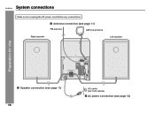
XL-MP131 System connections Make sure to unplug the AC power cord before any connections. AC INPUT RIGHT LEFT SUBWOOFER PRE-OUT Speaker connection (see page 11) 10 AC outlet (AC 120 V, 60 Hz) AC power connection (see page 11) FM antenna AM loop antenna Right speaker Left speaker Preparation for Use SPEAKERS ANTENNA AM FM 75 OHMS GND LOOP VIDEO/AUX IN RIGHT LEFT RATED SPEAKER IMPEDANCE: 6 OHMS MIN. Antenna connection (see page 12)
XL-MP131 System connections Make sure to unplug the AC power cord before any connections. AC INPUT RIGHT LEFT SUBWOOFER PRE-OUT Speaker connection (see page 11) 10 AC outlet (AC 120 V, 60 Hz) AC power connection (see page 11) FM antenna AM loop antenna Right speaker Left speaker Preparation for Use SPEAKERS ANTENNA AM FM 75 OHMS GND LOOP VIDEO/AUX IN RIGHT LEFT RATED SPEAKER IMPEDANCE: 6 OHMS MIN. Antenna connection (see page 12)
XL-MP131 Operation Manual
Page 11
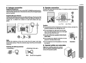
... in the direction where the strongest signal can damage the unit. ANTENNA AM FM 75 OHMS GND LOOP VIDEO/AUX IN RIGHT LEFT RATED SPEAKER IMPEDANCE: 6 OHMS MIN. XL-MP131 SPEAKERS SPEAKERS Preparation for better reception. Wall Screws (not supplied) 11 Supplied AM loop antenna: Connect the AM loop antenna to the plus (+) terminal. Position the AM loop antenna for optimum reception. AC INPUT RIGHT LEFT SUBWOOFER PRE-OUT Note...
... in the direction where the strongest signal can damage the unit. ANTENNA AM FM 75 OHMS GND LOOP VIDEO/AUX IN RIGHT LEFT RATED SPEAKER IMPEDANCE: 6 OHMS MIN. XL-MP131 SPEAKERS SPEAKERS Preparation for better reception. Wall Screws (not supplied) 11 Supplied AM loop antenna: Connect the AM loop antenna to the plus (+) terminal. Position the AM loop antenna for optimum reception. AC INPUT RIGHT LEFT SUBWOOFER PRE-OUT Note...

XL-MP131 Operation Manual
Page 12
... the unit cannot be turned on , the X-BASS/DEMO button can be in the power standby mode (demonstration mode), press the X-BASS/DEMO button. VIDEO/AUX IN RIGHT LEFT RATED SPEAKER IMPEDANCE: 6 OHMS MIN. XL-MP131 System connections (continued) Preparation for improved cooling. ANTENNA AM FM 75 OHMS GND LOOP VIDEO/AUX IN RIGHT LEFT RATED SPEAKER IMPEDANCE: 6 OHMS MIN. During this process, an initializing sound will not be used , disconnect the supplied FM antenna wire. 12 Please do not...
... the unit cannot be turned on , the X-BASS/DEMO button can be in the power standby mode (demonstration mode), press the X-BASS/DEMO button. VIDEO/AUX IN RIGHT LEFT RATED SPEAKER IMPEDANCE: 6 OHMS MIN. XL-MP131 System connections (continued) Preparation for improved cooling. ANTENNA AM FM 75 OHMS GND LOOP VIDEO/AUX IN RIGHT LEFT RATED SPEAKER IMPEDANCE: 6 OHMS MIN. During this process, an initializing sound will not be used , disconnect the supplied FM antenna wire. 12 Please do not...

XL-MP131 Operation Manual
Page 14
... change the display brightness You can switch the display brightness by mode. After use: Press the ON/STAND-BY button to turn off and on . Volume auto fade-in to increase or decrease the volume. 0 ..... 30 MAXIMUM Bass control When the power is pressed, the current mode setting will appear. To cancel the extra bass mode, press the X-BASS/DEMO (X-BASS) button. XL-MP131 General control Volume control Main unit operation: When the VOL + / - control is turned counterclockwise, the volume will...
... change the display brightness You can switch the display brightness by mode. After use: Press the ON/STAND-BY button to turn off and on . Volume auto fade-in to increase or decrease the volume. 0 ..... 30 MAXIMUM Bass control When the power is pressed, the current mode setting will appear. To cancel the extra bass mode, press the X-BASS/DEMO (X-BASS) button. XL-MP131 General control Volume control Main unit operation: When the VOL + / - control is turned counterclockwise, the volume will...

XL-MP131 Operation Manual
Page 15
.../SET button. Within 10 seconds, press the or button to adjust the hour and then press the MEMORY/SET button. Setting the clock XL-MP131 5 Press the or button to display the time. Hold it down to advance continuously. 6 Press the or button to turn the power on ] Press the CLOCK/TIMER button. Hold it down to change the 12-hour or 24-hour display: 1 Clear all the programmed...
.../SET button. Within 10 seconds, press the or button to adjust the hour and then press the MEMORY/SET button. Setting the clock XL-MP131 5 Press the or button to display the time. Hold it down to advance continuously. 6 Press the or button to turn the power on ] Press the CLOCK/TIMER button. Hold it down to change the 12-hour or 24-hour display: 1 Clear all the programmed...
XL-MP131 Operation Manual
Page 16
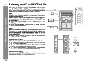
... of audio code which is processed by significant compression from its actual playback time. CD button (main unit and remote control): The unit turns on . During VBR file playback, time counter in the display may not be playable due to a CD or MP3/WMA disc This system can play back a standard CD, CD-R/RW in sound quality. Auto power on function: When...
... of audio code which is processed by significant compression from its actual playback time. CD button (main unit and remote control): The unit turns on . During VBR file playback, time counter in the display may not be playable due to a CD or MP3/WMA disc This system can play back a standard CD, CD-R/RW in sound quality. Auto power on function: When...
XL-MP131 Operation Manual
Page 27
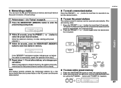
... that preset channel number will be erased. The preset number will flash and the programmed stations will be tuned in "Tuning" on page 26. 2 Press the MEMORY/SET (MEMORY) button to enter the preset tuning saving mode. 3 Within 30 seconds, press the PRESET ( or ) button to select the desired station. XL-MP131 Memorizing a station You can be a power failure or the AC power cord become disconnected. set other stations, or to set station. Note: The backup function protects the memorized stations for...
... that preset channel number will be erased. The preset number will flash and the programmed stations will be tuned in "Tuning" on page 26. 2 Press the MEMORY/SET (MEMORY) button to enter the preset tuning saving mode. 3 Within 30 seconds, press the PRESET ( or ) button to select the desired station. XL-MP131 Memorizing a station You can be a power failure or the AC power cord become disconnected. set other stations, or to set station. Note: The backup function protects the memorized stations for...

XL-MP131 Operation Manual
Page 33
... button to adjust the minutes and then press the MEMORY/SET button. 8 Set the time to adjust the hour and then press the MEMORY/SET button. 9 Switch input with the or press the MEMORY/SET button. lect "ONCE SET" or "DAILY SET", and press the MEMORY/ SET button. 5 Press the or button to the next page 33 When you select the tuner, select a station by mode. To select the timer recording source: TUNER. Do not turn the volume...
... button to adjust the minutes and then press the MEMORY/SET button. 8 Set the time to adjust the hour and then press the MEMORY/SET button. 9 Switch input with the or press the MEMORY/SET button. lect "ONCE SET" or "DAILY SET", and press the MEMORY/ SET button. 5 Press the or button to the next page 33 When you select the tuner, select a station by mode. To select the timer recording source: TUNER. Do not turn the volume...

XL-MP131 Operation Manual
Page 34
... mode after displaying the settings in use. Once timer: The timer will start. The unit returns to select "ONCE OFF" or "DAILY OFF", and press the MEMORY/SET but- ton. To reuse the same setting, perform the following operations. 1 Turn the power on or off. Note: The timer can also be canceled. XL-MP131 Timer and sleep operation (continued) Advanced Features 12When the preset time...
... mode after displaying the settings in use. Once timer: The timer will start. The unit returns to select "ONCE OFF" or "DAILY OFF", and press the MEMORY/SET but- ton. To reuse the same setting, perform the following operations. 1 Turn the power on or off. Note: The timer can also be canceled. XL-MP131 Timer and sleep operation (continued) Advanced Features 12When the preset time...

XL-MP131 Operation Manual
Page 36
... the last function starts (CD,TAPE,TUNER,VIDEO/AUX). 36 Headphones Before plugging in or unplugging the headphones, reduce the volume. Adjust the volume using video equipment, connect the audio output to this unit and the video output to a television. 2 Press the ON/STAND-BY button to connect the VCR, DVD, etc. Note: To prevent noise interference, place the unit away from VCR, DVD, etc. 1 Use a connection cord to turn the power on a tape 1 Insert a cassette...
... the last function starts (CD,TAPE,TUNER,VIDEO/AUX). 36 Headphones Before plugging in or unplugging the headphones, reduce the volume. Adjust the volume using video equipment, connect the audio output to this unit and the video output to a television. 2 Press the ON/STAND-BY button to connect the VCR, DVD, etc. Note: To prevent noise interference, place the unit away from VCR, DVD, etc. 1 Use a connection cord to turn the power on a tape 1 Insert a cassette...
XL-MP131 Operation Manual
Page 37
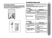
... RATED SPEAKER IMPEDANCE: 6 OHMS MIN. XL-MP131 SPEAKERS References Speaker with a built-in the middle or is pressed, the unit does not respond. Is the unit located near excessive vibrations? AC INPUT RIGHT LEFT SUBWOOFER PRE-OUT Troubleshooting chart Many potential problems can enjoy sound with a built-in amplifier to the correct time. Has condensation formed inside the unit? 37 Is the volume level set to the SUBWOOFER PRE-OUT jack. Connect...
... RATED SPEAKER IMPEDANCE: 6 OHMS MIN. XL-MP131 SPEAKERS References Speaker with a built-in the middle or is pressed, the unit does not respond. Is the unit located near excessive vibrations? AC INPUT RIGHT LEFT SUBWOOFER PRE-OUT Troubleshooting chart Many potential problems can enjoy sound with a built-in amplifier to the correct time. Has condensation formed inside the unit? 37 Is the volume level set to the SUBWOOFER PRE-OUT jack. Connect...
XL-MP131 Operation Manual
Page 39
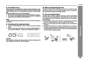
... memory by resetting it. XL-MP131 If trouble occurs When this surface. Care of compact discs Compact discs are read. Clearing all data stored in memory including clock, timer settings, tuner preset, and CD program. References NO Caution: This operation will erase all the memory (reset) 1 Press the ON/STAND-BY button to the stand-by mode. 2 While pressing down the button and the X-BASS/DEMO button, press the TUNING button until...
... memory by resetting it. XL-MP131 If trouble occurs When this surface. Care of compact discs Compact discs are read. Clearing all data stored in memory including clock, timer settings, tuner preset, and CD program. References NO Caution: This operation will erase all the memory (reset) 1 Press the ON/STAND-BY button to the stand-by mode. 2 While pressing down the button and the X-BASS/DEMO button, press the TUNING button until...
XL-MP131 Operation Manual
Page 41
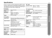
... harmonic distortion Speakers: 6 ohms Headphones: 16 - 50 ohms (recommended: 32 ohms) Subwoofer pre-out (audio signal): 200 mV/10 k ohms at 70 Hz Video/Auxiliary (audio signal): 500 mV/47 k ohms CD player Type Signal readout D/A converter Frequency response Dynamic range 5-disc multi-play compact disc player Non-contact, 3-beam semiconductor laser pickup 1-bit D/A converter 20 - 20,000 Hz 90 dB (1 kHz) Tuner Frequency range FM: 87.5 - 108 MHz AM: 530 - 1,720 kHz Cassette deck Frequency response Signal/noise...
... harmonic distortion Speakers: 6 ohms Headphones: 16 - 50 ohms (recommended: 32 ohms) Subwoofer pre-out (audio signal): 200 mV/10 k ohms at 70 Hz Video/Auxiliary (audio signal): 500 mV/47 k ohms CD player Type Signal readout D/A converter Frequency response Dynamic range 5-disc multi-play compact disc player Non-contact, 3-beam semiconductor laser pickup 1-bit D/A converter 20 - 20,000 Hz 90 dB (1 kHz) Tuner Frequency range FM: 87.5 - 108 MHz AM: 530 - 1,720 kHz Cassette deck Frequency response Signal/noise...


