Adjustment Guide
Page 3
... Standard Calibration...15 1.5.4 Copy Calibration by Dither Pattern...15 1.5.5 Printer Calibration by Dither Pattern ...16 1.5.6 Colour Copy Black Component Amount Adjustment 17 1.5.7 Area Separation Level Adjustment...17 1.6 Other Functions ...18 1.6.1 Main Charger Cleaner Operation ...18 1.6.2 PTC Cleaning ...18 1.6.3 Temperature/Humidity Display ...18 2 Image Position/Ratio/Area Adjustment 19 2.1 Ratio Adjustment ...19 2.1.1 Scan Ratio Adjustment ...19 2.2 Edge Adjustment...19 2.2.1 Scan Original Edge Adjustment ...19 2.2.2 Scan Original Edge Adjustment (Duplex Single Pass Feeder 20 3
... Standard Calibration...15 1.5.4 Copy Calibration by Dither Pattern...15 1.5.5 Printer Calibration by Dither Pattern ...16 1.5.6 Colour Copy Black Component Amount Adjustment 17 1.5.7 Area Separation Level Adjustment...17 1.6 Other Functions ...18 1.6.1 Main Charger Cleaner Operation ...18 1.6.2 PTC Cleaning ...18 1.6.3 Temperature/Humidity Display ...18 2 Image Position/Ratio/Area Adjustment 19 2.1 Ratio Adjustment ...19 2.1.1 Scan Ratio Adjustment ...19 2.2 Edge Adjustment...19 2.2.1 Scan Original Edge Adjustment ...19 2.2.2 Scan Original Edge Adjustment (Duplex Single Pass Feeder 20 3
Adjustment Guide
Page 4
...Area Adjustment ...20 2.3.1 Copy Image Loss Amount Settings ...20 2.3.2 Print Void Settings ...20 2.3.3 Duplex Single Pass Feeder Image Loss Amount Settings 21 2.3.4 Scanner Image Loss Amount Settings ...21 2.4 Off-Centre Adjustment...21 2.4.1 Print Off-Centre Adjustment ...21 2.4.2 Scan Original Off-Centre Adjustment ...22 2.4.3 Auto Centring Adjustment...22 3 Peripheral Adjustment...23 3.1 Saddle Finisher (When the 100-sheet saddle finisher is installed 23 3.1.1 Staple Position Adjustment...23 3.1.2 Paper Alignment Width Adjustment for Staple Position 23 3.1.3 Fold Position Adjustment for...
...Area Adjustment ...20 2.3.1 Copy Image Loss Amount Settings ...20 2.3.2 Print Void Settings ...20 2.3.3 Duplex Single Pass Feeder Image Loss Amount Settings 21 2.3.4 Scanner Image Loss Amount Settings ...21 2.4 Off-Centre Adjustment...21 2.4.1 Print Off-Centre Adjustment ...21 2.4.2 Scan Original Off-Centre Adjustment ...22 2.4.3 Auto Centring Adjustment...22 3 Peripheral Adjustment...23 3.1 Saddle Finisher (When the 100-sheet saddle finisher is installed 23 3.1.1 Staple Position Adjustment...23 3.1.2 Paper Alignment Width Adjustment for Staple Position 23 3.1.3 Fold Position Adjustment for...
Adjustment Guide
Page 5
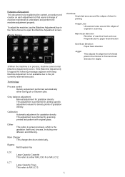
... by scanning printed test pattern with beep: Machine Adjustment is not available due to either during job or between jobs. Calibration Automatic adjustment for gradation density This adjustment is performed by setting specific adjustment values for density points of gradation density. Purpose of Document This document is for explaining the content, procedure and caution on each adjustment so that users in process, machine cannot enter [Machine Adjustment] screen. If the [Machine Adjustment] is...
... by scanning printed test pattern with beep: Machine Adjustment is not available due to either during job or between jobs. Calibration Automatic adjustment for gradation density This adjustment is performed by setting specific adjustment values for density points of gradation density. Purpose of Document This document is for explaining the content, procedure and caution on each adjustment so that users in process, machine cannot enter [Machine Adjustment] screen. If the [Machine Adjustment] is...
Adjustment Guide
Page 6
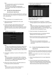
When auto adjustment is performed the value set in manual adjustment will be performed for each colour, use [Densitometer Adjustment] or [Visual Adjustment]. comes up when you do not want to clear the value. When a confirmation message appears, tap the [OK] key. Note: When the printing of the adjustment result fails, the following message appears: Printing test patch has failed. Tap the [Execute] key to the factory defaults. 4) A test patch is printed. The machine reboots to...
When auto adjustment is performed the value set in manual adjustment will be performed for each colour, use [Densitometer Adjustment] or [Visual Adjustment]. comes up when you do not want to clear the value. When a confirmation message appears, tap the [OK] key. Note: When the printing of the adjustment result fails, the following message appears: Printing test patch has failed. Tap the [Execute] key to the factory defaults. 4) A test patch is printed. The machine reboots to...
Adjustment Guide
Page 7
... scan) direction by measuring test patch visually. When a confirmation message appears, tap the [OK] key. Use A4 or 8 1/2" X 11" paper for each 6) When the adjustment is completed, a completion message appears and the adjustment result is printed. Note: All five values must be adjusted simultaneously. In the factory default state, this adjustment. The machine reboots to return to start the adjustment. Adjustment is performed by users. 1) Select [Densitometer Adjustment] in the Laser Adjustment screen. 2) To print a test...
... scan) direction by measuring test patch visually. When a confirmation message appears, tap the [OK] key. Use A4 or 8 1/2" X 11" paper for each 6) When the adjustment is completed, a completion message appears and the adjustment result is printed. Note: All five values must be adjusted simultaneously. In the factory default state, this adjustment. The machine reboots to return to start the adjustment. Adjustment is performed by users. 1) Select [Densitometer Adjustment] in the Laser Adjustment screen. 2) To print a test...

Adjustment Guide
Page 8
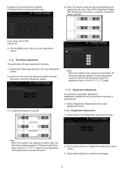
.... 5) Enter the desired values and tap the [Execute] key to the factory defaults. 3) A test patch containing 4 columns of adjustment points. Use A4 or 8 1/2" X 11" paper. When a confirmation message appears, tap the [OK] key. The machine reboots to return to start the adjustment. ◆When [4] is selected in the Laser Adjustment screen. 2) Correction Amounts are displayed (display only). 8 Note: When the printing of the adjustment result fails, the following message appears: Printing test patch has failed. Input...
.... 5) Enter the desired values and tap the [Execute] key to the factory defaults. 3) A test patch containing 4 columns of adjustment points. Use A4 or 8 1/2" X 11" paper. When a confirmation message appears, tap the [OK] key. The machine reboots to return to start the adjustment. ◆When [4] is selected in the Laser Adjustment screen. 2) Correction Amounts are displayed (display only). 8 Note: When the printing of the adjustment result fails, the following message appears: Printing test patch has failed. Input...
Adjustment Guide
Page 9
... the [Execute] key in Registration Adjustment (Auto) screen. 3) Tap the [Execute] key to print the adjustment result. Note: When the printing of the adjustment result fails, the following message appears: Printing test patch has failed. Use A3 or 11" X 17" paper. 3) An adjustment pattern is printed. If the [Print Adjustment Pattern After Registration.] checkbox is checked, adjustment result is printed. 1.1.6 Registration Adjustment This performs registration adjustment. Example of Correction Amount Display (Densitometer/Visual Adjustment) screen 4) Enter the desired value...
... the [Execute] key in Registration Adjustment (Auto) screen. 3) Tap the [Execute] key to print the adjustment result. Note: When the printing of the adjustment result fails, the following message appears: Printing test patch has failed. Use A3 or 11" X 17" paper. 3) An adjustment pattern is printed. If the [Print Adjustment Pattern After Registration.] checkbox is checked, adjustment result is printed. 1.1.6 Registration Adjustment This performs registration adjustment. Example of Correction Amount Display (Densitometer/Visual Adjustment) screen 4) Enter the desired value...
Adjustment Guide
Page 10
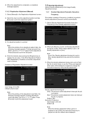
... makes a setting of the adjustment result fails, the following message appears: Printing test patch has failed. Input range: [1] to [99] Default: [50] for this adjustment. If the [Print Adjustment Pattern After Registration.] checkbox is checked, adjustment result is prior, set Density adjustment to [No]. Note: When the printing of Registration Adjustment screen 2) When job efficiency is set to [No], density adjustment may execute by machine state. 3) When the density adjustment during job: [Yes]: The process control adjustment...
... makes a setting of the adjustment result fails, the following message appears: Printing test patch has failed. Input range: [1] to [99] Default: [50] for this adjustment. If the [Print Adjustment Pattern After Registration.] checkbox is checked, adjustment result is prior, set Density adjustment to [No]. Note: When the printing of Registration Adjustment screen 2) When job efficiency is set to [No], density adjustment may execute by machine state. 3) When the density adjustment during job: [Yes]: The process control adjustment...
Adjustment Guide
Page 11
... to reboot the machine. 5) Tap the [OK] key to perform calibration before the rebooting starts.) 1.3 Fuser Adjustment Select [Fuser Adjustment] in the Density Adjustment (Forced Execution) screen. 3) The following message appears: When image density adjustment mode is executed, more toner is consumed, it ? Note: When plain paper or recycled paper is used, Set [Fusing Control Settings] of [Device Control] in [System Settings]. When unrecommend glossy paper or embossed is used, set paper property. After a certain...
... to reboot the machine. 5) Tap the [OK] key to perform calibration before the rebooting starts.) 1.3 Fuser Adjustment Select [Fuser Adjustment] in the Density Adjustment (Forced Execution) screen. 3) The following message appears: When image density adjustment mode is executed, more toner is consumed, it ? Note: When plain paper or recycled paper is used, Set [Fusing Control Settings] of [Device Control] in [System Settings]. When unrecommend glossy paper or embossed is used, set paper property. After a certain...
Adjustment Guide
Page 12
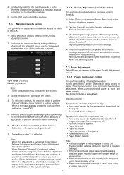
... images (print memory) appear due to register the setting. Note: To reflect the settings, the machine needs to reboot the machine. Note: To reset all items to [0], tap the [Return Entered Values to Zero] key. 3) Tap the [Register] key to adjust and enter the desired value. Example of Fusing Temperature Setting screen 2) Select the colour to register the setting. 1) Select [Fusing Temperature Settings] in the Fusing Adjustment screen. 2) To change...
... images (print memory) appear due to register the setting. Note: To reflect the settings, the machine needs to reboot the machine. Note: To reset all items to [0], tap the [Return Entered Values to Zero] key. 3) Tap the [Register] key to adjust and enter the desired value. Example of Fusing Temperature Setting screen 2) Select the colour to register the setting. 1) Select [Fusing Temperature Settings] in the Fusing Adjustment screen. 2) To change...
Adjustment Guide
Page 13
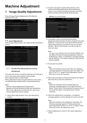
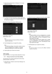
... paper or a special type of gradation density for each 3) Tap the [Register] key to register the setting. Example of Secondary Transfer Current Value Setting screen Input range: [-20] to Zero] key. 1.5 Image Quality Adjustment Select [Image Quality Adjustment] in copy mode by measuring test patch visually. Note: To reset all items to [0], tap the [Return Entered Values to [20] Default: [0] for printing in the Image Quality Adjustment screen. 1.5.1 Copy Colour Balance Adjustment This enables adjustment...
... paper or a special type of gradation density for each 3) Tap the [Register] key to register the setting. Example of Secondary Transfer Current Value Setting screen Input range: [-20] to Zero] key. 1.5 Image Quality Adjustment Select [Image Quality Adjustment] in copy mode by measuring test patch visually. Note: To reset all items to [0], tap the [Return Entered Values to [20] Default: [0] for printing in the Image Quality Adjustment screen. 1.5.1 Copy Colour Balance Adjustment This enables adjustment...

Adjustment Guide
Page 14
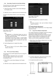
...] button again, print a print pattern, and check the results of the Copy Colour Balance Adjustment screen 2) To start the adjustment, tap the [Execute] key in the Printer Colour Balance Adjustment screen. 3) An adjustment pattern is checked, the value [500] appears in a Batch] checkbox. You will return to Default.] key. Note: To return your preferences to the factory defaults, tap the [Return Copy Colour Balance Adjustment Value to the Image Quality Adjustment screen. When a confirmation message appears...
...] button again, print a print pattern, and check the results of the Copy Colour Balance Adjustment screen 2) To start the adjustment, tap the [Execute] key in the Printer Colour Balance Adjustment screen. 3) An adjustment pattern is checked, the value [500] appears in a Batch] checkbox. You will return to Default.] key. Note: To return your preferences to the factory defaults, tap the [Return Copy Colour Balance Adjustment Value to the Image Quality Adjustment screen. When a confirmation message appears...
Adjustment Guide
Page 15
... a test patch fails, the following message appears: Auto adjustment has failed. Press [Execute] to adjust colour balance. This function uses the scanner to resume scanning. 15 After adjustment, tap the [Execute] button again, print a print pattern, and check the results of [Copy Calibration] and [Printer Calibration] are executed, tap the [Execute] key to move on the document glass. Please check if the test patch is properly set on the document glass(the thin line at...
... a test patch fails, the following message appears: Auto adjustment has failed. Press [Execute] to adjust colour balance. This function uses the scanner to resume scanning. 15 After adjustment, tap the [Execute] button again, print a print pattern, and check the results of [Copy Calibration] and [Printer Calibration] are executed, tap the [Execute] key to move on the document glass. Please check if the test patch is properly set on the document glass(the thin line at...

Adjustment Guide
Page 16
... fails, the following message appears: Printing test patch has failed. Place the test patch in portrait orientation. 5) When the adjustment is printed. The scanner can be used to perform fine adjustment of the printer colour balance of Printer Calibration by dither pattern screen. 6) Select the desired dither pattern and tap the [Execute] key to start the auto adjustment. Use A4 or 8 1/2" X 11" paper for this adjustment. Press [Execute] to the Image Quality Adjustment screen...
... fails, the following message appears: Printing test patch has failed. Place the test patch in portrait orientation. 5) When the adjustment is printed. The scanner can be used to perform fine adjustment of the printer colour balance of Printer Calibration by dither pattern screen. 6) Select the desired dither pattern and tap the [Execute] key to start the auto adjustment. Use A4 or 8 1/2" X 11" paper for this adjustment. Press [Execute] to the Image Quality Adjustment screen...
Adjustment Guide
Page 17
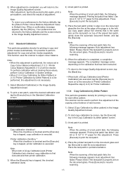
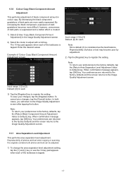
... copy. Input range: [-2] to [2] Default: [0] for each of photos or text may become poor by adjustment. 2) Tap the [Register] key to Default] key. When confirmation message appears, tap [OK] key. By increasing the black component, expression of Colour Copy Black Component Amount Adjustment screen. Note: To return your changes, tap the [Cancel] button. To cancel your preferences to the factory defaults, tap the [Return Area Separation Level Adjustment Value to register the setting...
... copy. Input range: [-2] to [2] Default: [0] for each of photos or text may become poor by adjustment. 2) Tap the [Register] key to Default] key. When confirmation message appears, tap [OK] key. By increasing the black component, expression of Colour Copy Black Component Amount Adjustment screen. Note: To return your changes, tap the [Cancel] button. To cancel your preferences to the factory defaults, tap the [Return Area Separation Level Adjustment Value to register the setting...
Adjustment Guide
Page 18
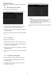
Caution: Fuser temperature adjustment stops when you enter the machine adjustment mode. Example of Temperature/Humidity Display screen. 2) To start the PTC cleaning operation, tap the [Execute] key in the PTC Cleaning screen. 3) When the cleaner operation is completed, a completion message appears. 4) To return to the Other Functions screen, tap the [Back] key. 1.6.3 Temperature/Humidity Display This shows temperature and humidity in the machine. 1) Select [Temperature/Humidity Display] in the Other Functions screen. Therefore, the displayed temperature...
Caution: Fuser temperature adjustment stops when you enter the machine adjustment mode. Example of Temperature/Humidity Display screen. 2) To start the PTC cleaning operation, tap the [Execute] key in the PTC Cleaning screen. 3) When the cleaner operation is completed, a completion message appears. 4) To return to the Other Functions screen, tap the [Back] key. 1.6.3 Temperature/Humidity Display This shows temperature and humidity in the machine. 1) Select [Temperature/Humidity Display] in the Other Functions screen. Therefore, the displayed temperature...

Adjustment Guide
Page 20
... a confirmation message appears, tap the [OK] key. Specify the Print Position Adjustment first. 2) Enter the desired values and tap the [Register] key. 2) Enter the desired values and tap the [Register] key. Input range: [0] to [99] (1 = 0.1 mm) Defaults: Edge image loss amount setting: [40] Side image loss amount setting: [20] Note: To return your preferences to the factory defaults, tap the [Return Original Scan Edge Adjustment Value (Duplex Single Pass Feeder) to Default] key...
... a confirmation message appears, tap the [OK] key. Specify the Print Position Adjustment first. 2) Enter the desired values and tap the [Register] key. 2) Enter the desired values and tap the [Register] key. Input range: [0] to [99] (1 = 0.1 mm) Defaults: Edge image loss amount setting: [40] Side image loss amount setting: [20] Note: To return your preferences to the factory defaults, tap the [Return Original Scan Edge Adjustment Value (Duplex Single Pass Feeder) to Default] key...
Adjustment Guide
Page 21
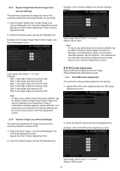
Specify the Print Position Adjustment first. 2) Enter the desired values and tap the [Register] key. 2) Enter the desired values and tap the [Register] key. Example of image loss amount for scanning original from document feeder in copy mode. 1) Select [Duplex Single Pass Feeder Image Loss Amount Settings] in the Void Area Adjustment screen. Input range: [0] to [99] (1 = 0.1 mm) Defaults: Side 1 lead edge image loss amount: [20] Side 1 side image loss amount: [20] Side 1 rear edge image loss...
Specify the Print Position Adjustment first. 2) Enter the desired values and tap the [Register] key. 2) Enter the desired values and tap the [Register] key. Example of image loss amount for scanning original from document feeder in copy mode. 1) Select [Duplex Single Pass Feeder Image Loss Amount Settings] in the Void Area Adjustment screen. Input range: [0] to [99] (1 = 0.1 mm) Defaults: Side 1 lead edge image loss amount: [20] Side 1 side image loss amount: [20] Side 1 rear edge image loss...
Adjustment Guide
Page 22
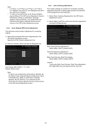
... the Print Position Adjustment first. 2) Enter the desired values and tap the [Register] key. Default: [ON] Sub Scan Direction Adjustment: Select [ON] or [OFF]. Your preferences are returned to the factory defaults and the screen returns to the Off-Centre Adjustment screen. Your preferences are returned to the factory defaults and the screen returns to the Off-Centre Adjustment screen. 2.4.3 Auto Centring Adjustment This makes settings of condition for automatic centring adjustment (function...
... the Print Position Adjustment first. 2) Enter the desired values and tap the [Register] key. Default: [ON] Sub Scan Direction Adjustment: Select [ON] or [OFF]. Your preferences are returned to the factory defaults and the screen returns to the Off-Centre Adjustment screen. Your preferences are returned to the factory defaults and the screen returns to the Off-Centre Adjustment screen. 2.4.3 Auto Centring Adjustment This makes settings of condition for automatic centring adjustment (function...
Adjustment Guide
Page 29
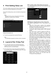
... the machine adjustment can be changed from the top left. Note: Settings that results in the screen is tapped, the ongoing entry on the 10-key pad are as follows: When the 10-key pad is opened, the numerical display shows by default the value currently shown in the textbox or the factory default value. A new entry made with an asterisk. 1) Check...
... the machine adjustment can be changed from the top left. Note: Settings that results in the screen is tapped, the ongoing entry on the 10-key pad are as follows: When the 10-key pad is opened, the numerical display shows by default the value currently shown in the textbox or the factory default value. A new entry made with an asterisk. 1) Check...


