
Service Manual
Page 1
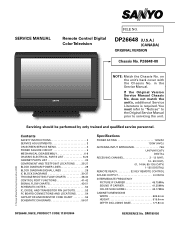
... FLOW CHARTS 38-40 CONTROL PORT FUNCTIONS 41-42 SIGNAL FLOW CHARTS 43-51 SCHEMATIC NOTES 52 IC, DIODE, AND TRANSISTOR PIN LAYOUTS 53 PC BOARD CONNECTIONS AND LOCATIONS 54 CAPACITOR AND ...RESISTOR CODE CHART 55 SCHEMATIC DIAGRAMS 56-57 Specifications POWER RATING 120VAC 120W (AVG.) ANTENNA INPUT IMPEDANCE 75Ω UHF/VHF/CATV DIGITAL... 665.5mm HEIGHT 515.6mm DEPTH INCLUDING BASE 177.8mm © Sanyo Manufacturing Corporation 2008 DP26648, N6CE, PRODUCT CODE 113013904 REFERENCE No.
... FLOW CHARTS 38-40 CONTROL PORT FUNCTIONS 41-42 SIGNAL FLOW CHARTS 43-51 SCHEMATIC NOTES 52 IC, DIODE, AND TRANSISTOR PIN LAYOUTS 53 PC BOARD CONNECTIONS AND LOCATIONS 54 CAPACITOR AND ...RESISTOR CODE CHART 55 SCHEMATIC DIAGRAMS 56-57 Specifications POWER RATING 120VAC 120W (AVG.) ANTENNA INPUT IMPEDANCE 75Ω UHF/VHF/CATV DIGITAL... 665.5mm HEIGHT 515.6mm DEPTH INCLUDING BASE 177.8mm © Sanyo Manufacturing Corporation 2008 DP26648, N6CE, PRODUCT CODE 113013904 REFERENCE No.
Service Manual
Page 2
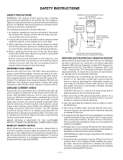
... in respect to each exposed antenna terminal (UHF and VHF antenna terminals). An isolation transformer must be located and corrected. When replacing a chassis in the schematic diagrams. To ensure safe product operation, it on the receiver. 2. Before replacing the back cover of electrical shock. Before returning any unit being serviced. 2. The...
... in respect to each exposed antenna terminal (UHF and VHF antenna terminals). An isolation transformer must be located and corrected. When replacing a chassis in the schematic diagrams. To ensure safe product operation, it on the receiver. 2. Before replacing the back cover of electrical shock. Before returning any unit being serviced. 2. The...
Service Manual
Page 9
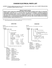
... Solid AL-SOLID........... Aluminium Solid ELECT Electrolytic NP-ELECT.......... COMPONENTS INDICATED BY A IN THIS PARTS LIST AND THE SCHEMATIC DIAGRAM DESIGNATE COMPONENTS IN WHICH SAFETY CAN BE OF SPECIAL SIGNIFICANCE. Ceramic MT-PAPER......... Polypropylene MT-POLYPRO.... Non-polarised... against electrical shock and for continued product safety, refer to SAFETY PRECAUTIONS, and PRODUCT SAFETY NOTICE on Page 2. Note: Schematic part location numbers may not always match with Organic Semiconductive Electrolytic RESISTORS NOTES: Read description of the Capacitor as follows: (...
... Solid AL-SOLID........... Aluminium Solid ELECT Electrolytic NP-ELECT.......... COMPONENTS INDICATED BY A IN THIS PARTS LIST AND THE SCHEMATIC DIAGRAM DESIGNATE COMPONENTS IN WHICH SAFETY CAN BE OF SPECIAL SIGNIFICANCE. Ceramic MT-PAPER......... Polypropylene MT-POLYPRO.... Non-polarised... against electrical shock and for continued product safety, refer to SAFETY PRECAUTIONS, and PRODUCT SAFETY NOTICE on Page 2. Note: Schematic part location numbers may not always match with Organic Semiconductive Electrolytic RESISTORS NOTES: Read description of the Capacitor as follows: (...
Service Manual
Page 52
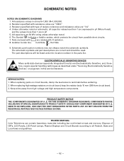
...LCD Panels, LCD Panel Lamps, Plasma Displays and Circuit Boards according to all capacitor values less than 1 are expressed in µF (Micro Farad), and the values more than 1 are 50 WV rating unless otherwise noted. 6. Isolation border line. The schematic... with X-radiation. 8. ELECTROSTATICALLY SENSATIVE DEVICES Many solid-state devices (especially Integrated Circuits) are "1/4." 4. Schematic part location numbers may not always match the schematic symbols. SERVICE NOTES: 1. PROPER DISPOSAL Color Televisions can contain hazardous materials including but not limited to terminals...
...LCD Panels, LCD Panel Lamps, Plasma Displays and Circuit Boards according to all capacitor values less than 1 are expressed in µF (Micro Farad), and the values more than 1 are 50 WV rating unless otherwise noted. 6. Isolation border line. The schematic... with X-radiation. 8. ELECTROSTATICALLY SENSATIVE DEVICES Many solid-state devices (especially Integrated Circuits) are "1/4." 4. Schematic part location numbers may not always match the schematic symbols. SERVICE NOTES: 1. PROPER DISPOSAL Color Televisions can contain hazardous materials including but not limited to terminals...
Service Manual
Page 56
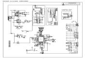
MODEL DP26648 Chassis No. SW1905 S10B0722J CH.+ VOL.- VOL.+ POWER SW1904 SW1903 SW1902 SW1901 ... as described under "Servicing Electrostatically Sensitive Devices," on page two in this service literature. P26648-00 SCHEMATIC DIAGRAMS 44 3 2 1 1 TO SPEAKER KSP J10EA043N L1614 1/10GZ0.0 C1609 KZ0.1 LZF C1610 ...P-FAIL2 IN AUDIO MUTE Reserve UART IN TV RELUELAADRYTCONOUTURTTL 17 18 19 20 21 22 23 24 25 26 27 28 29 30 31 32 16 Reserve... Panel Size0 Panel 14 Size1 13 Panel Size2 12 Panel Size3 11 PDP/LCD Vss 9 POWER IN ...
MODEL DP26648 Chassis No. SW1905 S10B0722J CH.+ VOL.- VOL.+ POWER SW1904 SW1903 SW1902 SW1901 ... as described under "Servicing Electrostatically Sensitive Devices," on page two in this service literature. P26648-00 SCHEMATIC DIAGRAMS 44 3 2 1 1 TO SPEAKER KSP J10EA043N L1614 1/10GZ0.0 C1609 KZ0.1 LZF C1610 ...P-FAIL2 IN AUDIO MUTE Reserve UART IN TV RELUELAADRYTCONOUTURTTL 17 18 19 20 21 22 23 24 25 26 27 28 29 30 31 32 16 Reserve... Panel Size0 Panel 14 Size1 13 Panel Size2 12 Panel Size3 11 PDP/LCD Vss 9 POWER IN ...
