Open Source Guide (ENGLISH)
Page 2
IN NO EVENT UNLESS REQUIRED BY APPLICABLE LAW OR AGREED TO IN WRITING WILL ANY COPYRIGHT HOLDER, OR ANY OTHER PARTY WHO MAY MODIFY AND/OR REDISTRIBUTE THE LIBRARY AS PERMITTED ABOVE, BE LIABLE TO YOU FOR DAMAGES, INCLUDING ANY GENERAL, SPECIAL, INCIDENTAL OR CONSEQUENTIAL DAMAGES ARISING OUT OF THE USE OR INABILITY TO USE THE LIBRARY (INCLUDING BUT NOT LIMITED TO LOSS OF DATA OR DATA BEING RENDERED INACCURATE OR LOSSES SUSTAINED BY YOU OR THIRD PARTIES OR A FAILURE OF THE LIBRARY TO OPERATE WITH ANY OTHER SOFTWARE), EVEN IF SUCH HOLDER OR OTHER PARTY HAS BEEN ADVISED OF THE POSSIBILITY OF SUCH...
IN NO EVENT UNLESS REQUIRED BY APPLICABLE LAW OR AGREED TO IN WRITING WILL ANY COPYRIGHT HOLDER, OR ANY OTHER PARTY WHO MAY MODIFY AND/OR REDISTRIBUTE THE LIBRARY AS PERMITTED ABOVE, BE LIABLE TO YOU FOR DAMAGES, INCLUDING ANY GENERAL, SPECIAL, INCIDENTAL OR CONSEQUENTIAL DAMAGES ARISING OUT OF THE USE OR INABILITY TO USE THE LIBRARY (INCLUDING BUT NOT LIMITED TO LOSS OF DATA OR DATA BEING RENDERED INACCURATE OR LOSSES SUSTAINED BY YOU OR THIRD PARTIES OR A FAILURE OF THE LIBRARY TO OPERATE WITH ANY OTHER SOFTWARE), EVEN IF SUCH HOLDER OR OTHER PARTY HAS BEEN ADVISED OF THE POSSIBILITY OF SUCH...
User Manual (ENGLISH)
Page 2
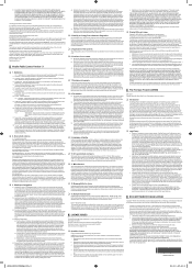
... unit accompanying this product unit to encode and/or decode audio files conforming to the ISO/IEC 11172-3 or ISO/IEC 13818-3. © 2006 Samsung Electronics Co., Ltd. This license is limited to the ISO/IEC 11172-3 or ISO/IEC 13818-3. Several of transmitting high quality video and audio... to Dolby Digital 5.1 surround, using your TV set. The license does not cover any product unit other than this product unit and the license does not extend to any unlicensed product unit or...
... unit accompanying this product unit to encode and/or decode audio files conforming to the ISO/IEC 11172-3 or ISO/IEC 13818-3. © 2006 Samsung Electronics Co., Ltd. This license is limited to the ISO/IEC 11172-3 or ISO/IEC 13818-3. Several of transmitting high quality video and audio... to Dolby Digital 5.1 surround, using your TV set. The license does not cover any product unit other than this product unit and the license does not extend to any unlicensed product unit or...
User Manual (ENGLISH)
Page 3
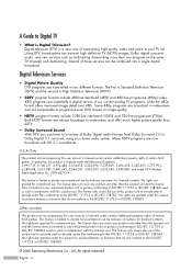
... DTV reception. It is decoded at the receiver, the digital video and audio data is possible that you need is an antenna and a DTV set-top receiver to produce high-quality images and sound. Q&A 1. The same holds true for DTV? Once the DTV signal level exceeds a certain ... of an apartment complex can provide broadcast DTV signals via a master TV antenna system to receive DTV signals indoors? This is that the landlord of broadcast TV signals as long as analog TV and works well with broadcast DTV set -top receiver to receive DTV broadcasts. Is the antenna I connect ...
... DTV reception. It is decoded at the receiver, the digital video and audio data is possible that you need is an antenna and a DTV set-top receiver to produce high-quality images and sound. Q&A 1. The same holds true for DTV? Once the DTV signal level exceeds a certain ... of an apartment complex can provide broadcast DTV signals via a master TV antenna system to receive DTV signals indoors? This is that the landlord of broadcast TV signals as long as analog TV and works well with broadcast DTV set -top receiver to receive DTV broadcasts. Is the antenna I connect ...
User Manual (ENGLISH)
Page 4
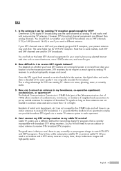
...Front Panel LED Indicators 10 Front side buttons 11 Side Panel Jacks ...11 Rear Panel Jacks ...12 Remote Control...13 Connections 16 Connecting VHF and UHF Antennas 16 Antennas with 75-ohm Round Leads 16 Connecting Cable TV 17 Cable without a Cable Box 17 Cable with a Cable Box that Descrambles... DVI (Digital Visual Interface 23 Connecting a VCR and DTV Set-Top Box 24 Connecting to HDMI (High Definition Multimedia Interface 24 Connecting a Digital Audio System 25 Connecting to an Analog Amplifier 26 Operation 28 Turning the TV On and Off 28 Dynamic Menus and On-Screen Displays 28...
...Front Panel LED Indicators 10 Front side buttons 11 Side Panel Jacks ...11 Rear Panel Jacks ...12 Remote Control...13 Connections 16 Connecting VHF and UHF Antennas 16 Antennas with 75-ohm Round Leads 16 Connecting Cable TV 17 Cable without a Cable Box 17 Cable with a Cable Box that Descrambles... DVI (Digital Visual Interface 23 Connecting a VCR and DTV Set-Top Box 24 Connecting to HDMI (High Definition Multimedia Interface 24 Connecting a Digital Audio System 25 Connecting to an Analog Amplifier 26 Operation 28 Turning the TV On and Off 28 Dynamic Menus and On-Screen Displays 28...
User Manual (ENGLISH)
Page 5
...60 DNIe (Digital Natural Image engine 61 Setting the My Color Control Mode 62 Using the Color Weakness Enhancement Feature 64 Setting the Film Mode 65 Freezing the Picture 66 Setting the Blue Screen Mode 67 Sound Control 70 Sound Control ...70 Setting the SRS TSXT 72 Auto Volume...73...100 Using Your TV as a Computer (PC) Display 100 Adjusting the Picture Quality 103 Changing the Picture Position 104 Adjusting the Picture Quality and Position Automatically 105 Changing the Picture Size (PC Mode 106 Viewing the Current Resolution 107 Initializing the Picture Settings 108 WISELINK ...
...60 DNIe (Digital Natural Image engine 61 Setting the My Color Control Mode 62 Using the Color Weakness Enhancement Feature 64 Setting the Film Mode 65 Freezing the Picture 66 Setting the Blue Screen Mode 67 Sound Control 70 Sound Control ...70 Setting the SRS TSXT 72 Auto Volume...73...100 Using Your TV as a Computer (PC) Display 100 Adjusting the Picture Quality 103 Changing the Picture Position 104 Adjusting the Picture Quality and Position Automatically 105 Changing the Picture Size (PC Mode 106 Viewing the Current Resolution 107 Initializing the Picture Settings 108 WISELINK ...
User Manual (ENGLISH)
Page 9
... from the front panel or remote control • Automatic timer to turn the TV on and off at any time you choose • Adjustable picture and sound settings and the ability to memorize your favorite settings • Automatic channel tuning for up to 181 channels • A special ...-in multi-channel sound decoder for stereo and bilingual listening • Built-in, dual channel speakers • A special sleep timer • Widescreen TV with adjustable image size • Life-like clear images provided by DNle technology • My Color Control mode to correspond with your dealer. In ...
... from the front panel or remote control • Automatic timer to turn the TV on and off at any time you choose • Adjustable picture and sound settings and the ability to memorize your favorite settings • Automatic channel tuning for up to 181 channels • A special ...-in multi-channel sound decoder for stereo and bilingual listening • Built-in, dual channel speakers • A special sleep timer • Widescreen TV with adjustable image size • Life-like clear images provided by DNle technology • My Color Control mode to correspond with your dealer. In ...
User Manual (ENGLISH)
Page 10
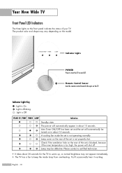
... : Light is not operating normally. You'll occasionally hear it working. Remote Control Sensor Aim the remote control towards this spot on the rear of the set is not properly shut. A cooling fan inside lamp from overheating. Check if the ventilation hole on in about 15 seconds. The picture will...Lights POWER Press to keep the inside the set will automatically appear in about 30 seconds for the TV to warm up, so normal brightness may not appear immediately. • The TV has a fan to turn the TV on the model. Lamp cover on the TV. The product color and shape may be ...
... : Light is not operating normally. You'll occasionally hear it working. Remote Control Sensor Aim the remote control towards this spot on the rear of the set is not properly shut. A cooling fan inside lamp from overheating. Check if the ventilation hole on in about 15 seconds. The picture will...Lights POWER Press to keep the inside the set will automatically appear in about 30 seconds for the TV to warm up, so normal brightness may not appear immediately. • The TV has a fan to turn the TV on the model. Lamp cover on the TV. The product color and shape may be ...
User Manual (ENGLISH)
Page 12
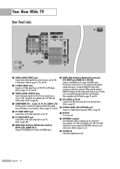
These jacks are available only in TV, Video and S-Video modes. (Refer to page 24) ¨ COMPONENT IN 1, 2 jacks (Y, PB, PR, AUDIO L/R) Use these jacks to connect the component video/audio signals from a DVD player or a Set-Top Box. (Refer to pages 21 and 23) ˆ PC VIDEO INPUT jack ... connection with HDMI output. Use "ANT 1 IN (CABLE)" and "ANT 2 IN (AIR)" terminals to receive a signal from the TV to an external source, such as a VCR. English - 12 Your New Wide TV Rear Panel Jacks Œ VIDEO/AUDIO INPUT jacks Connect video/audio signals from external sources, such as VCR or DVD...
These jacks are available only in TV, Video and S-Video modes. (Refer to page 24) ¨ COMPONENT IN 1, 2 jacks (Y, PB, PR, AUDIO L/R) Use these jacks to connect the component video/audio signals from a DVD player or a Set-Top Box. (Refer to pages 21 and 23) ˆ PC VIDEO INPUT jack ... connection with HDMI output. Use "ANT 1 IN (CABLE)" and "ANT 2 IN (AIR)" terminals to receive a signal from the TV to an external source, such as a VCR. English - 12 Your New Wide TV Rear Panel Jacks Œ VIDEO/AUDIO INPUT jacks Connect video/audio signals from external sources, such as VCR or DVD...
User Manual (ENGLISH)
Page 13
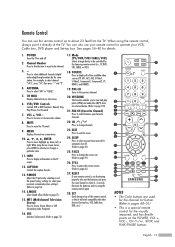
...1. See pages 34~40 for automatic shut off . 2. Press to select additional channels (digital and analog) being broadcast by selecting one of the preset factory settings (or select your remote control is a special remote control for about 23 feet from an external device. (Refer to select "AIR" or "CABLE". 5..../STB/CABLE/VCR) Selects a target device to the previous channel. 20. PRE-CH Tunes to be controlled by the Samsung remote control (i.e., TV, DVD, STB, CABLE, or VCR). 18. P.SIZE Press to change the screen size. (Refer to display information on -screen menu. 10 ENTER ...
...1. See pages 34~40 for automatic shut off . 2. Press to select additional channels (digital and analog) being broadcast by selecting one of the preset factory settings (or select your remote control is a special remote control for about 23 feet from an external device. (Refer to select "AIR" or "CABLE". 5..../STB/CABLE/VCR) Selects a target device to the previous channel. 20. PRE-CH Tunes to be controlled by the Samsung remote control (i.e., TV, DVD, STB, CABLE, or VCR). 18. P.SIZE Press to change the screen size. (Refer to display information on -screen menu. 10 ENTER ...
User Manual (ENGLISH)
Page 18
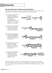
... connection you will need a two-way splitter, an RF (A/B) switch, and four coaxial cables (which is connected to the ANTENNA IN terminal of your Samsung dealer or any electronics store). 1 Find and disconnect the cable that Descrambles Some (But Not All) Channels To complete this cable to a two-way ... of the RF (A/B) switch and the ANT 1 IN (CABLE) on the TV. After you've made this connection, set the A/B switch to "B", you will need to tune your Set-Top Box to the Cable box's output channel, which you set the A/B switch to view scrambled channels. (When you can buy from your ...
... connection you will need a two-way splitter, an RF (A/B) switch, and four coaxial cables (which is connected to the ANTENNA IN terminal of your Samsung dealer or any electronics store). 1 Find and disconnect the cable that Descrambles Some (But Not All) Channels To complete this cable to a two-way ... of the RF (A/B) switch and the ANT 1 IN (CABLE) on the TV. After you've made this connection, set the A/B switch to "B", you will need to tune your Set-Top Box to the Cable box's output channel, which you set the A/B switch to view scrambled channels. (When you can buy from your ...
User Manual (ENGLISH)
Page 19
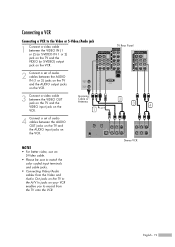
TV Rear Panel 2 3 4 Stereo VCR English - 19 Incoming Cable or Antenna 1 or 4 Connect a set of audio cables between the VIDEO OUT jack on the TV and the VIDEO input jack on the VCR. NOTES • For better video, use an S-Video cable. • Please be sure to match the color ... a video cable between the VIDEO IN (1 or 2) (or S-VIDEO IN 1 or 2) jack on the TV and the VIDEO (or S-VIDEO) output jack on the VCR. 2 Connect a set of audio cables between the AUDIO IN (1 or 2) jacks on the TV and the AUDIO output jacks on the VCR. 3 Connect a video cable between the AUDIO...
TV Rear Panel 2 3 4 Stereo VCR English - 19 Incoming Cable or Antenna 1 or 4 Connect a set of audio cables between the VIDEO OUT jack on the TV and the VIDEO input jack on the VCR. NOTES • For better video, use an S-Video cable. • Please be sure to match the color ... a video cable between the VIDEO IN (1 or 2) (or S-VIDEO IN 1 or 2) jack on the TV and the VIDEO (or S-VIDEO) output jack on the VCR. 2 Connect a set of audio cables between the AUDIO IN (1 or 2) jacks on the TV and the AUDIO output jacks on the VCR. 3 Connect a video cable between the AUDIO...
User Manual (ENGLISH)
Page 20
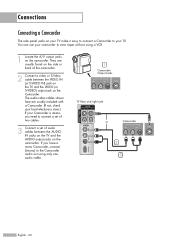
... VCR. 1 Locate the A/V output jacks on the camcorder. If you need to view tapes without using only one audio cable. 1 Camcorder Output Jacks TV Rear and right side or Camcorder 2 3 English - 20 Connections Connecting a Camcorder The side panel jacks on the Camcorder. The audio-video cables shown here ... cables between the VIDEO IN (or S-VIDEO IN) jack on the TV and the VIDEO (or S-VIDEO) output jack on your TV make it easy to connect a Camcorder to your camcorder to connect a set of two cables. 3 Connect a set of the camcorder. 2 Connect a video or S-Video cable between the...
... VCR. 1 Locate the A/V output jacks on the camcorder. If you need to view tapes without using only one audio cable. 1 Camcorder Output Jacks TV Rear and right side or Camcorder 2 3 English - 20 Connections Connecting a Camcorder The side panel jacks on the Camcorder. The audio-video cables shown here ... cables between the VIDEO IN (or S-VIDEO IN) jack on the TV and the VIDEO (or S-VIDEO) output jack on your TV make it easy to connect a Camcorder to your camcorder to connect a set of two cables. 3 Connect a set of the camcorder. 2 Connect a video or S-Video cable between the...
User Manual (ENGLISH)
Page 21
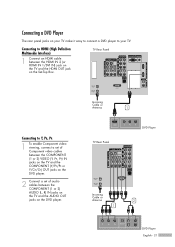
TV Rear Panel Connecting to Y, PB, PR 1 To enable Component video viewing, connect a set of Component video cables between the COMPONENT (1 or 2) VIDEO (Y, PB, PR) IN jacks on the TV and the COMPONENT (Y/PB/PR or Y/CB/CR) OUT jacks on the DVD player. 2 Connect a set of audio cables between the ... Set-Top Box. Connecting to your TV make it easy to connect a DVD player to HDMI (High Definition Multimedia Interface) 1 Connect an HDMI cable between the COMPONENT (1 or 2) AUDIO (L, R) IN jacks on the TV and the AUDIO OUT jacks on the DVD player. Incoming Cable or Antenna 1 TV Rear ...
TV Rear Panel Connecting to Y, PB, PR 1 To enable Component video viewing, connect a set of Component video cables between the COMPONENT (1 or 2) VIDEO (Y, PB, PR) IN jacks on the TV and the COMPONENT (Y/PB/PR or Y/CB/CR) OUT jacks on the DVD player. 2 Connect a set of audio cables between the ... Set-Top Box. Connecting to your TV make it easy to connect a DVD player to HDMI (High Definition Multimedia Interface) 1 Connect an HDMI cable between the COMPONENT (1 or 2) AUDIO (L, R) IN jacks on the TV and the AUDIO OUT jacks on the DVD player. Incoming Cable or Antenna 1 TV Rear ...
User Manual (ENGLISH)
Page 22
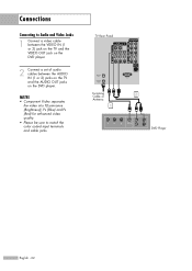
TV Rear Panel Incoming Cable or Antenna 1 2 DVD Player English - 22 NOTES • Component Video separates the video into Y(Luminance (Brightness)), PB (Blue) and PR (Red) for enhanced video quality. • Please be sure to Audio and Video Jacks 1 Connect a video cable between the VIDEO IN (1 or 2) jack on the TV and the VIDEO OUT jack on the DVD player. 2 Connect a set of audio cables between the AUDIO IN (1 or 2) jacks on the TV and the AUDIO OUT jacks on the DVD player. Connections Connecting to match the color coded input terminals and cable jacks.
TV Rear Panel Incoming Cable or Antenna 1 2 DVD Player English - 22 NOTES • Component Video separates the video into Y(Luminance (Brightness)), PB (Blue) and PR (Red) for enhanced video quality. • Please be sure to Audio and Video Jacks 1 Connect a video cable between the VIDEO IN (1 or 2) jack on the TV and the VIDEO OUT jack on the DVD player. 2 Connect a set of audio cables between the AUDIO IN (1 or 2) jacks on the TV and the AUDIO OUT jacks on the DVD player. Connections Connecting to match the color coded input terminals and cable jacks.
User Manual (ENGLISH)
Page 23
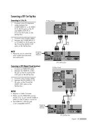
... HDMI IN 1/DVI IN jack on the TV and the DVI OUT jack on the Set-Top Box. 2 Connect a set of audio cables between the COMPONENT (1 or 2) AUDIO (L, R) IN jacks on the TV and the AUDIO OUT jacks on the Set-Top Box. DTV Set-Top Box TV Rear Panel NOTES • Requires a Cable Converter.... • Make sure the HDMI/DVI source's power is not compatible with PC. Connecting a DTV Set-Top Box Connecting to Y, PB, PR 1 Connect...
... HDMI IN 1/DVI IN jack on the TV and the DVI OUT jack on the Set-Top Box. 2 Connect a set of audio cables between the COMPONENT (1 or 2) AUDIO (L, R) IN jacks on the TV and the AUDIO OUT jacks on the Set-Top Box. DTV Set-Top Box TV Rear Panel NOTES • Requires a Cable Converter.... • Make sure the HDMI/DVI source's power is not compatible with PC. Connecting a DTV Set-Top Box Connecting to Y, PB, PR 1 Connect...
User Manual (ENGLISH)
Page 24
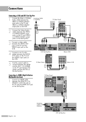
... splitter and the ANT 1 IN (CABLE) on the TV and between the splitter and the ANT IN on the Set-Top Box. TV Rear Panel or 1 Stereo VCR Stereo VCR 4 English - 24 Incoming Cable or Antenna 1 DTV Set-Top Box Connections Connecting a VCR and DTV Set-Top Box 1 Connect the Video or S-Video/ Audio... the VIDEO or S-VIDEO/AUDIO input jacks on the TV and VIDEO or S-VIDEO/AUDIO output jacks on the Set-Top Box. Incoming Cable or Antenna TV Rear Panel 2 Connect the Video/Audio cables between the VIDEO 5 or S-VIDEO/AUDIO input jacks on the TV and VIDEO or S-VIDEO/AUDIO output 2 jacks on...
... splitter and the ANT 1 IN (CABLE) on the TV and between the splitter and the ANT IN on the Set-Top Box. TV Rear Panel or 1 Stereo VCR Stereo VCR 4 English - 24 Incoming Cable or Antenna 1 DTV Set-Top Box Connections Connecting a VCR and DTV Set-Top Box 1 Connect the Video or S-Video/ Audio... the VIDEO or S-VIDEO/AUDIO input jacks on the TV and VIDEO or S-VIDEO/AUDIO output jacks on the Set-Top Box. Incoming Cable or Antenna TV Rear Panel 2 Connect the Video/Audio cables between the VIDEO 5 or S-VIDEO/AUDIO input jacks on the TV and VIDEO or S-VIDEO/AUDIO output 2 jacks on...
User Manual (ENGLISH)
Page 25
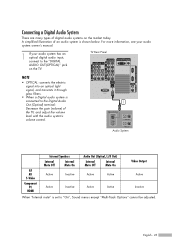
...connected to "On", Sound menus except "Multi-Track Options" cannot be adjusted. A simplified illustration of digital audio systems on the TV. English - 25 TV Rear Panel NOTE • OPTICAL: converts the electric signal into an optical light signal, and transmits it through glass fibers. •...; When a Digital audio system is set to the Digital Audio 1 Out (Optical) terminal: Decrease the gain (volume) of the TV, and ...
...connected to "On", Sound menus except "Multi-Track Options" cannot be adjusted. A simplified illustration of digital audio systems on the TV. English - 25 TV Rear Panel NOTE • OPTICAL: converts the electric signal into an optical light signal, and transmits it through glass fibers. •...; When a Digital audio system is set to the Digital Audio 1 Out (Optical) terminal: Decrease the gain (volume) of the TV, and ...
User Manual (ENGLISH)
Page 26
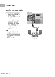
You must hook them up to an Analog Amplifier 1 The "AV OUT (AUDIO L/R)" terminals cannot be used for external speakers. NOTE • If using the HDMI/DVI, PC, or Component input on the TV, the audio output signal is available only when the TV's Internal Mute is connected to the "AV OUT (AUDIO L/R)" terminals: Decrease the gain (volume) of the TV, and adjust the volume level with the volume control on . (Refer to on your audio amplifier. Connections Connecting to an amplifier. When an audio amplifier is set to page 76) TV Rear Panel 1 Amplifier English - 26
You must hook them up to an Analog Amplifier 1 The "AV OUT (AUDIO L/R)" terminals cannot be used for external speakers. NOTE • If using the HDMI/DVI, PC, or Component input on the TV, the audio output signal is available only when the TV's Internal Mute is connected to the "AV OUT (AUDIO L/R)" terminals: Decrease the gain (volume) of the TV, and adjust the volume level with the volume control on . (Refer to on your audio amplifier. Connections Connecting to an amplifier. When an audio amplifier is set to page 76) TV Rear Panel 1 Amplifier English - 26
User Manual (ENGLISH)
Page 28
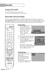
Viewing the Menus 1 Press the MENU button. The main menu will appear at the bottom of certain picture, sound settings and the current time. There are seven menu groups: "Input", "Picture", "Sound", "Channel", "Setup", "Application", and "Menu Map". The information displayed varies according to exit...or † button, then press the ENTER button to return to select an item you to control the settings of your remote control to display, change, or use the POWER button on your TV. You can also view the on the remote control. Press the ENTER button to select menu items and...
Viewing the Menus 1 Press the MENU button. The main menu will appear at the bottom of certain picture, sound settings and the current time. There are seven menu groups: "Input", "Picture", "Sound", "Channel", "Setup", "Application", and "Menu Map". The information displayed varies according to exit...or † button, then press the ENTER button to return to select an item you to control the settings of your remote control to display, change, or use the POWER button on your TV. You can also view the on the remote control. Press the ENTER button to select menu items and...

User Manual (ENGLISH)
Page 32
The TV begins memorizing all available stations. Select "Return" by using the number buttons on the STB. Even if a particular channel is deleted from the memory, you want to select another type of cable system, press the œ or √ button to a Set-Top Box, Channel Memorization is set to... Move Enter Return • STD, HRC and IRC identify various types of cable system that channel directly by pressing the ... By default, the cable TV system is done on the remote control. • When connecting Digital Cable to select "STD", "HRC" or "IRC". or † button, ...
The TV begins memorizing all available stations. Select "Return" by using the number buttons on the STB. Even if a particular channel is deleted from the memory, you want to select another type of cable system, press the œ or √ button to a Set-Top Box, Channel Memorization is set to... Move Enter Return • STD, HRC and IRC identify various types of cable system that channel directly by pressing the ... By default, the cable TV system is done on the remote control. • When connecting Digital Cable to select "STD", "HRC" or "IRC". or † button, ...


