User Manual (ENGLISH)
Page 11
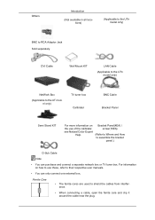
... separately DVI Cable Wall Mount KIT LAN Cable (Applicable to the UTn model only) NetWork Box (Applicable to their respective user manuals. • You can purchase and connect a separate network box or TV tuner box. For information on how to use these, refer to the UT model only) TV tuner box Calibrater BNC Cable Bracket Panel Semi Stand KIT For more information on the use of the calibrater, see Natural Color Expert Help. Ferrite Core...
... separately DVI Cable Wall Mount KIT LAN Cable (Applicable to the UTn model only) NetWork Box (Applicable to their respective user manuals. • You can purchase and connect a separate network box or TV tuner box. For information on how to use these, refer to the UT model only) TV tuner box Calibrater BNC Cable Bracket Panel Semi Stand KIT For more information on the use of the calibrater, see Natural Color Expert Help. Ferrite Core...
User Manual (ENGLISH)
Page 13
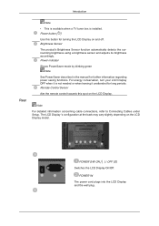
... concerning cable connections, refer to Connecting Cables under Setup. POWER S/W ON [ │ ] / OFF [O] Switches the LCD Display On/Off. Remote Control Sensor Aim the remote control towards this button for turning the LCD Display on the LCD Display. POWER IN The power cord plugs into the LCD Display and the wall plug. Power button [ ] Use this spot on and off. For energy conservation, turn your LCD Display OFF when it is installed. The LCD Display 's configuration at the back may vary slightly depending on the LCD Display model. Introduction Rear Note...
... concerning cable connections, refer to Connecting Cables under Setup. POWER S/W ON [ │ ] / OFF [O] Switches the LCD Display On/Off. Remote Control Sensor Aim the remote control towards this button for turning the LCD Display on the LCD Display. POWER IN The power cord plugs into the LCD Display and the wall plug. Power button [ ] Use this spot on and off. For energy conservation, turn your LCD Display OFF when it is installed. The LCD Display 's configuration at the back may vary slightly depending on the LCD Display model. Introduction Rear Note...
User Manual (ENGLISH)
Page 20
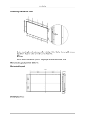
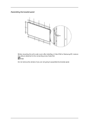
Mechanical Layout (460UT, 460UTn) Mechanical Layout LCD Display Head Assembling the bracket panel Introduction Before mounting the set's outer cover after installing a Video Wall or Samsung UD, remove the stickers attached to assemble the bracket panel. Note Do not remove the stickers if you are not going to the connecting screw holes first.
Mechanical Layout (460UT, 460UTn) Mechanical Layout LCD Display Head Assembling the bracket panel Introduction Before mounting the set's outer cover after installing a Video Wall or Samsung UD, remove the stickers attached to assemble the bracket panel. Note Do not remove the stickers if you are not going to the connecting screw holes first.
User Manual (ENGLISH)
Page 27
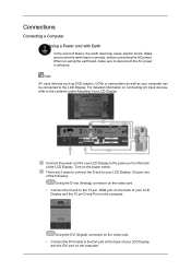
...: Using the D-sub (Analog) connector on the video card. • Connect the D-sub to the power port on the computer. Make sure to disconnect the AC power in correctly, before connecting the AC power. Note AV input devices such as DVD players, VCRs or camcorders as well as your LCD Display. Turn on the computer. Using the DVI (Digital) connector on the video card. • Connect the DVI Cable to...
...: Using the D-sub (Analog) connector on the video card. • Connect the D-sub to the power port on the computer. Make sure to disconnect the AC power in correctly, before connecting the AC power. Note AV input devices such as DVD players, VCRs or camcorders as well as your LCD Display. Turn on the computer. Using the DVI (Digital) connector on the video card. • Connect the DVI Cable to...
User Manual (ENGLISH)
Page 30
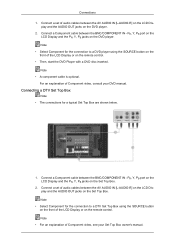
... Component video, consult your Set Top Box owner's manual. Connections 1. Connect a Component cable between the AV AUDIO IN [L-AUDIO-R] on the LCD Display and the AUDIO OUT jacks on the Set Top Box. Connect a Component cable between the AV AUDIO IN [L-AUDIO-R] on the remote control. PR, Y, PB port on the LCD Display and the PR, Y, PB jacks on the remote control. • Then, start the DVD Player with a DVD disc inserted. Connecting a DTV Set Top Box Note • The connections for the connection to a DTV Set Top Box using...
... Component video, consult your Set Top Box owner's manual. Connections 1. Connect a Component cable between the AV AUDIO IN [L-AUDIO-R] on the LCD Display and the AUDIO OUT jacks on the Set Top Box. Connect a Component cable between the AV AUDIO IN [L-AUDIO-R] on the remote control. PR, Y, PB port on the LCD Display and the PR, Y, PB jacks on the remote control. • Then, start the DVD Player with a DVD disc inserted. Connecting a DTV Set Top Box Note • The connections for the connection to a DTV Set Top Box using...
User Manual (ENGLISH)
Page 34
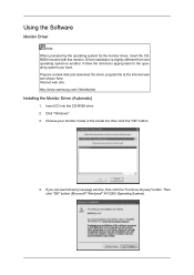
Prepare a blank disk and download the driver program file at the Internet web site shown here. Click "Windows". 3. Follow the directions appropriate for the monitor driver, insert the CDROM included with this monitor. Internet web site : http://www.samsung.com/ (Worldwide) Installing the Monitor Driver (Automatic) 1. If you have. Then click "OK" button (Microsoft® Windows® XP/2000 Operating System). Using the Software Monitor Driver Note When prompted...
Prepare a blank disk and download the driver program file at the Internet web site shown here. Click "Windows". 3. Follow the directions appropriate for the monitor driver, insert the CDROM included with this monitor. Internet web site : http://www.samsung.com/ (Worldwide) Installing the Monitor Driver (Automatic) 1. If you have. Then click "OK" button (Microsoft® Windows® XP/2000 Operating System). Using the Software Monitor Driver Note When prompted...
User Manual (ENGLISH)
Page 35
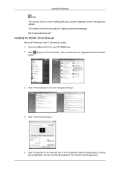
... (Start) and "Control Panel". Click "Properties" in the "Monitor" tab. Using the Software Note This monitor driver is under certifying MS logo, and this installation doesn't damage your CD-ROM drive. 2. Then, double-click on Samsung Monitor homepage. ization". 3. Click "Advanced Settings...". 5. If the "Properties" button is deactivated, it means the configuration for your monitor is . The certified driver will be used as is completed...
... (Start) and "Control Panel". Click "Properties" in the "Monitor" tab. Using the Software Note This monitor driver is under certifying MS logo, and this installation doesn't damage your CD-ROM drive. 2. Then, double-click on Samsung Monitor homepage. ization". 3. Click "Advanced Settings...". 5. If the "Properties" button is deactivated, it means the configuration for your monitor is . The certified driver will be used as is completed...
User Manual (ENGLISH)
Page 40
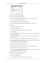
... "Close" button. Click "Start", "Setting", "Control Panel". 2. Microsoft® Windows® Millennium Operating System 1. Double click the "Display" icon. 3. Choose your monitor, follow next steps continually. 5. Using the Software 10. Monitor driver installation is completed. Microsoft® Windows® 2000 Operating System When you can choose a specific driver" then click "Next" and then click "Have disk". 7. Choose "OK" button on the "Next" button. 6. Click the "Browse" button on "Update Driver..." Double...
... "Close" button. Click "Start", "Setting", "Control Panel". 2. Microsoft® Windows® Millennium Operating System 1. Double click the "Display" icon. 3. Choose your monitor, follow next steps continually. 5. Using the Software 10. Monitor driver installation is completed. Microsoft® Windows® 2000 Operating System When you can choose a specific driver" then click "Next" and then click "Have disk". 7. Choose "OK" button on the "Next" button. 6. Click the "Browse" button on "Update Driver..." Double...
User Manual (ENGLISH)
Page 41
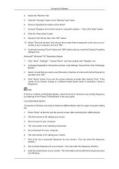
Choose "Specify the location of X-Window. Select "Show all devices" and choose the monitor that you wish to use (Resolution, Number of system setting file. 1. nected to make the X86Config file, which is not normal, change to the Preset Timing Modes in the user guide. If the screen is a type of colors and Vertical frequency) and then click "OK". 4. The next screen is for your monitor. 7. Set a Keyboard...
Choose "Specify the location of X-Window. Select "Show all devices" and choose the monitor that you wish to use (Resolution, Number of system setting file. 1. nected to make the X86Config file, which is not normal, change to the Preset Timing Modes in the user guide. If the screen is a type of colors and Vertical frequency) and then click "OK". 4. The next screen is for your monitor. 7. Set a Keyboard...

User Manual (ENGLISH)
Page 43
... start the program. Installation Problems The installation of computer system or monitor. Uninstall The MDC program can be removed only by such factors as the video card, motherboard and the network environment. When the Installation Shield Wizard window appears, click "Next". 4. If that happens, press F5 Key. The "Installation Status" window appears. 7. Using the Software MDC For detailed instructions, install the Eye-One Display and run...
... start the program. Installation Problems The installation of computer system or monitor. Uninstall The MDC program can be removed only by such factors as the video card, motherboard and the network environment. When the Installation Shield Wizard window appears, click "Next". 4. If that happens, press F5 Key. The "Installation Status" window appears. 7. Using the Software MDC For detailed instructions, install the Eye-One Display and run...

User Manual (ENGLISH)
Page 56
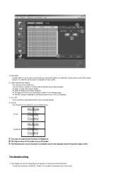
... display. 3) Brightness - Adjusts Tint of MagicInfo works only on MagicInfo model. Adjusts the Color Temp for TV, AV, S-Video, Component, HDMI, DTV. 2) Contrast - The Input source of the selected display. - When each function fetches the value for the displays whose power status is ON and if no selection is made, the factory default is displayed in this screen will automatically change the mode to Settings Control. Available only for the selected display. 9) Brightness Sensor - Adjusts...
... display. 3) Brightness - Adjusts Tint of MagicInfo works only on MagicInfo model. Adjusts the Color Temp for TV, AV, S-Video, Component, HDMI, DTV. 2) Contrast - The Input source of the selected display. - When each function fetches the value for the displays whose power status is ON and if no selection is made, the factory default is displayed in this screen will automatically change the mode to Settings Control. Available only for the selected display. 9) Brightness Sensor - Adjusts...
User Manual (ENGLISH)
Page 62
... format can select a number of the selected display. 4) Format - z Select a mode from Display Selection. The Maintenance Control function is available only for the displays where the power status is repeated on the Power Control Info Grid - Troubleshooting 1. 1) Video Wall - Check the connection of the whole picture or so that the same picture is ON. Turns on TV model. The screen can be set of video screens that are connected together, so that each screen shows a part...
... format can select a number of the selected display. 4) Format - z Select a mode from Display Selection. The Maintenance Control function is available only for the displays where the power status is repeated on the Power Control Info Grid - Troubleshooting 1. 1) Video Wall - Check the connection of the whole picture or so that the same picture is ON. Turns on TV model. The screen can be set of video screens that are connected together, so that each screen shows a part...
User Manual (ENGLISH)
Page 65
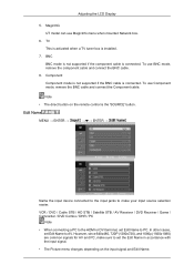
... connected. To use MagicInfo menu when mounted Network box. 6. Component Component mode is not supported if the BNC cable is installed. 7. VCR / DVD / Cable STB / HD STB / Satellite STB / AV Receiver / DVD Receiver / Game / Camcorder / DVD Combo / DHR / PC Note • When connecting a PC to the HDMI or DVI terminal, set Edit Name to set the Edit Name in accordance with the input signal. • The Picture menu changes depending on the remote control is connected. To use Component mode, remove the BNC cable and connect the Component cable...
... connected. To use MagicInfo menu when mounted Network box. 6. Component Component mode is not supported if the BNC cable is installed. 7. VCR / DVD / Cable STB / HD STB / Satellite STB / AV Receiver / DVD Receiver / Game / Camcorder / DVD Combo / DHR / PC Note • When connecting a PC to the HDMI or DVI terminal, set Edit Name to set the Edit Name in accordance with the input signal. • The Picture menu changes depending on the remote control is connected. To use Component mode, remove the BNC cable and connect the Component cable...

User Manual (ENGLISH)
Page 97
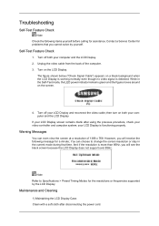
... view the screen at a resolution of the computer. 3. Contact a Service Center for the resolutions or frequencies supported by yourself. Note Refer to change the screen resolution or stay in the Self-Test mode, the LED power indicator remains green and the figure moves around on the LCD Display. Unplug the video cable from the back of 1366 x 768. Warning Messages You can choose to Specifications > Preset Timing Modes for problems that time...
... view the screen at a resolution of the computer. 3. Contact a Service Center for the resolutions or frequencies supported by yourself. Note Refer to change the screen resolution or stay in the Self-Test mode, the LED power indicator remains green and the figure moves around on the LCD Display. Unplug the video cable from the back of 1366 x 768. Warning Messages You can choose to Specifications > Preset Timing Modes for problems that time...

User Manual (ENGLISH)
Page 98
... Safe Mode, remove the Display Adaptor in the "Control Panel −> System −> Device Administrator" and then reboot the computer to between 50 Hz ~ 85 Hz. (Do not exceed 60Hz when using the maximum resolution.) 5. Check if the power cord and the video cables are listed. Check List Note • The following table lists possible problems and their solutions are properly connected to the screen. 2) Maintaining the Flat Panel Display Screen. Q: The LCD Display screen...
... Safe Mode, remove the Display Adaptor in the "Control Panel −> System −> Device Administrator" and then reboot the computer to between 50 Hz ~ 85 Hz. (Do not exceed 60Hz when using the maximum resolution.) 5. Check if the power cord and the video cables are listed. Check List Note • The following table lists possible problems and their solutions are properly connected to the screen. 2) Maintaining the Flat Panel Display Screen. Q: The LCD Display screen...
User Manual (ENGLISH)
Page 103
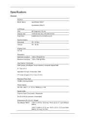
Specifications General General Model Name SyncMaster 460UT SyncMaster 460UTn LCD Panel Size Display area Pixel Pitch 46" Diagonal (116 cm) 1018.353 mm (H) x 572.544 mm (V) 0.2485 mm (H) x 0.7455 mm (V) Synchronization Horizontal Vertical 30 ~ 81 kHz 56 ~ 85 Hz Display Color 16.7 M Resolution Optimum resolution 1366 x 768 @ 60 Hz Maximum resolution 1920 x 1080 @ 60Hz Input Signal, Terminated RGB Analog, DVI(Digital Visual Interface) Compliant Digital RGB 0.7 Vp-p ±5 % Separate...
Specifications General General Model Name SyncMaster 460UT SyncMaster 460UTn LCD Panel Size Display area Pixel Pitch 46" Diagonal (116 cm) 1018.353 mm (H) x 572.544 mm (V) 0.2485 mm (H) x 0.7455 mm (V) Synchronization Horizontal Vertical 30 ~ 81 kHz 56 ~ 85 Hz Display Color 16.7 M Resolution Optimum resolution 1366 x 768 @ 60 Hz Maximum resolution 1920 x 1080 @ 60Hz Input Signal, Terminated RGB Analog, DVI(Digital Visual Interface) Compliant Digital RGB 0.7 Vp-p ±5 % Separate...
User Manual (ENGLISH)
Page 104
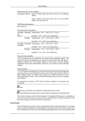
... normal operation when The LCD Display automatically returns to change without any Plug & Play compatible system. The interaction of the LCD Display and the computer systems will proceed automatically, unless the user wishes to be bright sometimes or some black pixels may be used for a certain amount of RED, GREEN, BLUE and WHITE color appear to select alternate settings. Specifications Dimensions (W x H x D) / Weight SyncMaster 460UTn 1025.7 x 579.8 x 130.0 mm / 40.4 x 22.8 x 5.1 inch (Without Stand...
... normal operation when The LCD Display automatically returns to change without any Plug & Play compatible system. The interaction of the LCD Display and the computer systems will proceed automatically, unless the user wishes to be bright sometimes or some black pixels may be used for a certain amount of RED, GREEN, BLUE and WHITE color appear to select alternate settings. Specifications Dimensions (W x H x D) / Weight SyncMaster 460UTn 1025.7 x 579.8 x 130.0 mm / 40.4 x 22.8 x 5.1 inch (Without Stand...
Quick Guide (ENGLISH)
Page 12
Note Do not remove the stickers if you are not going to the connecting screw holes first. Assembling the bracket panel Before mounting the set's outer cover after installing a Video Wall or Samsung UD, remove the stickers attached to assemble the bracket panel.
Note Do not remove the stickers if you are not going to the connecting screw holes first. Assembling the bracket panel Before mounting the set's outer cover after installing a Video Wall or Samsung UD, remove the stickers attached to assemble the bracket panel.

Quick Guide (ENGLISH)
Page 13
... power in correctly, before connecting the AC power. Turn on connecting AV input devices, refer to the DVI port on the back of your LCD Display to wire the earth lead in advance. Using the DVI (Digital) connector on the video card. • Connect the DVI Cable to the contents under Adjusting Your LCD Display. Choose one of the following: Using the D-sub (Analog) connector on the video card. • Connect...
... power in correctly, before connecting the AC power. Turn on connecting AV input devices, refer to the DVI port on the back of your LCD Display to wire the earth lead in advance. Using the DVI (Digital) connector on the video card. • Connect the DVI Cable to the contents under Adjusting Your LCD Display. Choose one of the following: Using the D-sub (Analog) connector on the video card. • Connect...
Quick Guide (ENGLISH)
Page 19
...-Test mode, the LED power indicator remains green and the figure moves around on both your video controller and computer system; Self-Test Feature Check 1. Warning Messages You can choose to Specifications > Preset Timing Modes for problems that time. You can even view the screen at a resolution of the computer. 3. Contact a Service Center for the resolutions or frequencies supported by yourself. Turn on a black background when the LCD Display is working normally...
...-Test mode, the LED power indicator remains green and the figure moves around on both your video controller and computer system; Self-Test Feature Check 1. Warning Messages You can choose to Specifications > Preset Timing Modes for problems that time. You can even view the screen at a resolution of the computer. 3. Contact a Service Center for the resolutions or frequencies supported by yourself. Turn on a black background when the LCD Display is working normally...


