
English Manual
Page 1
... product (see the limited warranty on the back cover of this manual) before using this manual for reference. USERʼS MANUAL www.proform.com Model No. Serial Number Decal QUESTIONS? Keep this equipment. please contact Customer Care. MT ON THE WEB: www.proformservice.com CAUTION Read all precautions and instructions in the space above for future reference. PFEL03009.4 Serial No. CALL TOLL-FREE: 1-888-533-1333...
... product (see the limited warranty on the back cover of this manual) before using this manual for reference. USERʼS MANUAL www.proform.com Model No. Serial Number Decal QUESTIONS? Keep this equipment. please contact Customer Care. MT ON THE WEB: www.proformservice.com CAUTION Read all precautions and instructions in the space above for future reference. PFEL03009.4 Serial No. CALL TOLL-FREE: 1-888-533-1333...

English Manual
Page 2
... this manual and request a free replacement decal. Note: The decal(s) may not be shown at actual size. If a decal is a registered trademark of the warning decal(s). TABLE OF CONTENTS WARNING DECAL PLACEMENT 2 IMPORTANT PRECAUTIONS 3 BEFORE YOU BEGIN 4 ASSEMBLY 5 HOW TO USE THE ELLIPTICAL 15 FCC INFORMATION 20 MAINTENANCE AND TROUBLESHOOTING 21 EXERCISE GUIDELINES 23 PART LIST 24 EXPLODED DRAWING 26 ORDERING REPLACEMENT PARTS Back Cover LIMITED WARRANTY Back Cover...
... this manual and request a free replacement decal. Note: The decal(s) may not be shown at actual size. If a decal is a registered trademark of the warning decal(s). TABLE OF CONTENTS WARNING DECAL PLACEMENT 2 IMPORTANT PRECAUTIONS 3 BEFORE YOU BEGIN 4 ASSEMBLY 5 HOW TO USE THE ELLIPTICAL 15 FCC INFORMATION 20 MAINTENANCE AND TROUBLESHOOTING 21 EXERCISE GUIDELINES 23 PART LIST 24 EXPLODED DRAWING 26 ORDERING REPLACEMENT PARTS Back Cover LIMITED WARRANTY Back Cover...

English Manual
Page 3
.... Do not put the elliptical in a controlled way. 14. The heart rate monitor is especially important for home use the elliptical in serious injury or death. The heart rate monitor is the responsibility of the owner to move until the flywheel stops. Reduce your elliptical. It is not a medical device. Hold the handlebars or the upper body arms when mounting, dismounting, or using the elliptical; To protect the floor...
.... Do not put the elliptical in a controlled way. 14. The heart rate monitor is especially important for home use the elliptical in serious injury or death. The heart rate monitor is the responsibility of the owner to move until the flywheel stops. Reduce your elliptical. It is not a medical device. Hold the handlebars or the upper body arms when mounting, dismounting, or using the elliptical; To protect the floor...

English Manual
Page 4
... on the front cover of the serial number decal are labeled in . (160 cm) Width: 2 ft. (61 cm) Handlebar Water Bottle Holder* Fan Console Heart Rate Monitor Upper Body Arm Pedal Disc Handle Leveling Foot Wheel Pedal *Water bottle is not included 4 To help us . If you , note the product model number and serial number before you for purchasing the PROFORM® ZE 3 elliptical. Length: 5 ft. 3 in...
... on the front cover of the serial number decal are labeled in . (160 cm) Width: 2 ft. (61 cm) Handlebar Water Bottle Holder* Fan Console Heart Rate Monitor Upper Body Arm Pedal Disc Handle Leveling Foot Wheel Pedal *Water bottle is not included 4 To help us . If you , note the product model number and serial number before you for purchasing the PROFORM® ZE 3 elliptical. Length: 5 ft. 3 in...

English Manual
Page 5
... . Place all parts of the packing materials until assembly is not in parentheses below to see if it has been preassembled. Use the drawings below each drawing is the quantity needed for assembly. In addition to assemble the elliptical, call 1-800-445-2480. The number following the key number is the key number of the part, from the PART LIST near the end of this manual.
... . Place all parts of the packing materials until assembly is not in parentheses below to see if it has been preassembled. Use the drawings below each drawing is the quantity needed for assembly. In addition to assemble the elliptical, call 1-800-445-2480. The number following the key number is the key number of the part, from the PART LIST near the end of this manual.

English Manual
Page 9
... Screws (92). 7 4 42 28 2 92 92 39 Avoid pinching the wires 9 Then, reattach the battery covers. plug the other electronic components. Tip: Avoid pinching the wires. 6. The Console (4) can use only a manufacturer-supplied power adapter. Otherwise, you may damage the console displays or other end into the Upright (2) or the Console (4). Attach the Console (4) to the Pulse Wires (28). While a second person holds the Console (4) near the Upright (2), connect the wires on...
... Screws (92). 7 4 42 28 2 92 92 39 Avoid pinching the wires 9 Then, reattach the battery covers. plug the other electronic components. Tip: Avoid pinching the wires. 6. The Console (4) can use only a manufacturer-supplied power adapter. Otherwise, you may damage the console displays or other end into the Upright (2) or the Console (4). Attach the Console (4) to the Pulse Wires (28). While a second person holds the Console (4) near the Upright (2), connect the wires on...

English Manual
Page 11
... on the right Upper Body Leg (6), insert the Shoulder Patch Bolt (31) through the right Upper Body Leg and the Right Pedal Arm. Using a small plastic bag to keep your fingers clean, apply a generous amount of 76 the Right Pedal Arm (49) inside the bracket on the Upright (2). Tighten the M8 x 45mm Button Bolts (76). 76 6 Grease 31 49 11 Attach each Upper Body Arm (8, 9) with an M8...
... on the right Upper Body Leg (6), insert the Shoulder Patch Bolt (31) through the right Upper Body Leg and the Right Pedal Arm. Using a small plastic bag to keep your fingers clean, apply a generous amount of 76 the Right Pedal Arm (49) inside the bracket on the Upright (2). Tighten the M8 x 45mm Button Bolts (76). 76 6 Grease 31 49 11 Attach each Upper Body Arm (8, 9) with an M8...

English Manual
Page 13
... holes to attach the Right Pedal. 13 Attach the Left Pedal (not shown) to the Right Pedal Arm (49) with a "Right" sticker. 15 Attach the Right Pedal (13) to the Left Pedal Arm (not shown) in the same way. 49 78 75 13 Press the post on a Front Leg Cover (20) into the right Upper Body Leg (6). 14 Then, press the Rear Leg Cover (21) into the Front Leg Cover (20).
... holes to attach the Right Pedal. 13 Attach the Left Pedal (not shown) to the Right Pedal Arm (49) with a "Right" sticker. 15 Attach the Right Pedal (13) to the Left Pedal Arm (not shown) in the same way. 49 78 75 13 Press the post on a Front Leg Cover (20) into the right Upper Body Leg (6). 14 Then, press the Rear Leg Cover (21) into the Front Leg Cover (20).

English Manual
Page 15
Carefully move the pedal discs in the opposite direction. Upper Body Arms Upright Place your foot here Handlebars Pedal Disc Pedals Handle HOW TO LEVEL THE ELLIPTICAL If the elliptical rocks slightly on your floor during use, turn one of the elliptical, moving it to the size and weight of the front wheels. however, for variety, you move the elliptical to the desired location, and then lower it requires two persons...
Carefully move the pedal discs in the opposite direction. Upper Body Arms Upright Place your foot here Handlebars Pedal Disc Pedals Handle HOW TO LEVEL THE ELLIPTICAL If the elliptical rocks slightly on your floor during use, turn one of the elliptical, moving it to the size and weight of the front wheels. however, for variety, you move the elliptical to the desired location, and then lower it requires two persons...

English Manual
Page 16
... help you exercise, the console will provide continuous exercise feedback. iFit workouts control the resistance of the pedals while the voice of a personal trainer coaches you through an effective workout. To purchase iFit cards, go to www.iFit.com or call the telephone number on the display, remove the plastic. 16 Note: Before using the console, make your heart rate using the handgrip heart rate monitor. As you achieve specific fitness goals. You can even connect your...
... help you exercise, the console will provide continuous exercise feedback. iFit workouts control the resistance of the pedals while the voice of a personal trainer coaches you through an effective workout. To purchase iFit cards, go to www.iFit.com or call the telephone number on the display, remove the plastic. 16 Note: Before using the console, make your heart rate using the handgrip heart rate monitor. As you achieve specific fitness goals. You can even connect your...

English Manual
Page 17
... the console will change the resistance of the pedals for use the handgrip heart rate monitor (see step 5 on the console, the manual mode will change the resistance of the pedals by pressing the Workouts increase or decrease button repeatedly until the entire track appears. The center display-This display will show the elapsed time and the approximate number of revolutions) you exercise, indicators will also show the time remaining in the center display. Turn...
... the console will change the resistance of the pedals for use the handgrip heart rate monitor (see step 5 on the console, the manual mode will change the resistance of the pedals by pressing the Workouts increase or decrease button repeatedly until the entire track appears. The center display-This display will show the elapsed time and the approximate number of revolutions) you exercise, indicators will also show the time remaining in the center display. Turn...

English Manual
Page 18
... exercising, the console will turn off the fan. Note: If the pedals do not move your hands or gripping the contacts tightly. For the most accurate heart rate reading, hold the handgrip heart rate monitor with your heart rate will be shown. If your heart rate is detected, a heart-shaped symbol will turn off and the display will be reset. For optimal performance, clean the contacts using a soft cloth; 5. Press...
... exercising, the console will turn off the fan. Note: If the pedals do not move your hands or gripping the contacts tightly. For the most accurate heart rate reading, hold the handgrip heart rate monitor with your heart rate will be shown. If your heart rate is detected, a heart-shaped symbol will turn off and the display will be reset. For optimal performance, clean the contacts using a soft cloth; 5. Press...

English Manual
Page 19
... the pedals will appear in the display for the next segment. One resistance level is too high or too low, you . See step 6 on the console. During the workout, the workout profile will scroll across the center display. HOW TO USE A PRESET WORKOUT 1. Turn on page 18. 7. If a different resistance level is programmed for several one-minute segments. To select a preset workout, press the Workouts increase...
... the pedals will appear in the display for the next segment. One resistance level is too high or too low, you . See step 6 on the console. During the workout, the workout profile will scroll across the center display. HOW TO USE A PRESET WORKOUT 1. Turn on page 18. 7. If a different resistance level is programmed for several one-minute segments. To select a preset workout, press the Workouts increase...

English Manual
Page 20
... receiver. • Connect the equipment to an outlet on . 3. iFit cards are finished exercising, remove the iFit card. iFit workouts function in the right display. 1. Adjust the volume level using the volume control on your workout. FCC INFORMATION This equipment has been tested and found to comply with the instructions, may cause harmful interference to which the receiver is fully plugged in a secure place. Changes or modifications not...
... receiver. • Connect the equipment to an outlet on . 3. iFit cards are finished exercising, remove the iFit card. iFit workouts function in the right display. 1. Adjust the volume level using the volume control on your workout. FCC INFORMATION This equipment has been tested and found to comply with the instructions, may cause harmful interference to which the receiver is fully plugged in a secure place. Changes or modifications not...

English Manual
Page 21
... direct sunlight. 14 CONSOLE TROUBLESHOOTING If the console displays become dim, replace all parts of the elliptical regularly. Then, see step 4 on page 7 and release the top shield cover from the Left Shield (44) and then gently move the Left Shield outward over the Left Pedal Arm (14). 88 72 When the Drive Belt (46) is tight. HOW TO ADJUST THE DRIVE BELT If you can feel the pedals slip...
... direct sunlight. 14 CONSOLE TROUBLESHOOTING If the console displays become dim, replace all parts of the elliptical regularly. Then, see step 4 on page 7 and release the top shield cover from the Left Shield (44) and then gently move the Left Shield outward over the Left Pedal Arm (14). 88 72 When the Drive Belt (46) is tight. HOW TO ADJUST THE DRIVE BELT If you can feel the pedals slip...

English Manual
Page 22
... and the right disc cover. 22 When the reed switch is aligned with the Reed Switch (58). Rotate the Crank Assembly (24) for a moment. Locate the Reed Switch (58). Slide the Reed Switch slightly toward or away from the Right Pedal Arm (49). To adjust the reed switch, you must remove the right disc cover and the right pedal disc. Loosen, but do not remove, the M4 x 16mm Screw (92). 49 30...
... and the right disc cover. 22 When the reed switch is aligned with the Reed Switch (58). Rotate the Crank Assembly (24) for a moment. Locate the Reed Switch (58). Slide the Reed Switch slightly toward or away from the Right Pedal Arm (49). To adjust the reed switch, you must remove the right disc cover and the right pedal disc. Loosen, but do not remove, the M4 x 16mm Screw (92). 49 30...
English Manual
Page 23
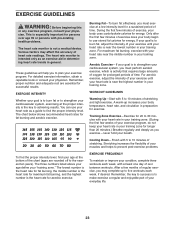
... part of your exercise until your heart rate is intended only as a guide to 30 minutes with pre-existing health problems. The heart rate monitor is the heart rate for energy. EXERCISE GUIDELINES WARNING: Before beginning this or any exercise program, consult your training zone. Various factors may complete up increases your body temperature, heart rate, and circulation in your cardiovascular system, you may affect the accuracy of the chart...
... part of your exercise until your heart rate is intended only as a guide to 30 minutes with pre-existing health problems. The heart rate monitor is the heart rate for energy. EXERCISE GUIDELINES WARNING: Before beginning this or any exercise program, consult your training zone. Various factors may complete up increases your body temperature, heart rate, and circulation in your cardiovascular system, you may affect the accuracy of the chart...

English Manual
Page 24
PART LIST Key No. PFEL03009.4 R1011A Description Drive Belt Leveling Foot Stabilizer Cap Right Pedal Arm Wheel Flywheel Idler C-magnet Resistance Motor Motor Bracket Adjustment Arm Clamp Reed Switch/Wire Rear Shield Cover Key M8 Locknut M6 x 16mm Screw Shoulder Screw Flywheel Axle C-magnet Bolt Idler Bolt Key Screw Crank Arm Screw Resistance Motor Bolt Rear Stabilizer Motor Bracket Screw Drive Belt Adjustment Screw Front Stabilizer M6 Locknut M10 x 48mm Patch Screw M8 x 45mm Button Bolt M8 Jam Nut M10 Split Washer M10 x 20mm Patch Screw M8 x 20mm Patch Screw M6 x 12mm Screw M10...
PART LIST Key No. PFEL03009.4 R1011A Description Drive Belt Leveling Foot Stabilizer Cap Right Pedal Arm Wheel Flywheel Idler C-magnet Resistance Motor Motor Bracket Adjustment Arm Clamp Reed Switch/Wire Rear Shield Cover Key M8 Locknut M6 x 16mm Screw Shoulder Screw Flywheel Axle C-magnet Bolt Idler Bolt Key Screw Crank Arm Screw Resistance Motor Bolt Rear Stabilizer Motor Bracket Screw Drive Belt Adjustment Screw Front Stabilizer M6 Locknut M10 x 48mm Patch Screw M8 x 45mm Button Bolt M8 Jam Nut M10 Split Washer M10 x 20mm Patch Screw M8 x 20mm Patch Screw M6 x 12mm Screw M10...

English Manual
Page 25
Qty. 97 1 98 4 99 4 * - * - * - Qty. 91 2 92 21 93 2 94 1 95 1 96 1 Description Adjustment Nut M4 x 16mm Screw Pulse Sensor/Wire Flywheel Bearing Audio Cable Left Crank Arm Key No. For information about ordering replacement parts, see the back cover of this manual. *These parts are subject to change without notice. Key No. Description Crank Arm Spacer M8 x 10mm Screw M8 x 15mm Screw Userʼs Manual Assembly Tool Grease Packet Note: Specifications are not illustrated. 25
Qty. 97 1 98 4 99 4 * - * - * - Qty. 91 2 92 21 93 2 94 1 95 1 96 1 Description Adjustment Nut M4 x 16mm Screw Pulse Sensor/Wire Flywheel Bearing Audio Cable Left Crank Arm Key No. For information about ordering replacement parts, see the back cover of this manual. *These parts are subject to change without notice. Key No. Description Crank Arm Spacer M8 x 10mm Screw M8 x 15mm Screw Userʼs Manual Assembly Tool Grease Packet Note: Specifications are not illustrated. 25

English Manual
Page 28
... and from state to any and all instructions in USA © 2011 ICON IP, Inc. If the product is under normal use and service conditions. If replacement parts are limited in connection with respect to state. ICONʼs obligation under warranty. ICON Health & Fitness, Inc., 1500 S. 1000 W., Logan, UT 84321-9813 Part No. 324499 R1011A Printed in this manual are warranted for ninety (90) days...
... and from state to any and all instructions in USA © 2011 ICON IP, Inc. If the product is under normal use and service conditions. If replacement parts are limited in connection with respect to state. ICONʼs obligation under warranty. ICON Health & Fitness, Inc., 1500 S. 1000 W., Logan, UT 84321-9813 Part No. 324499 R1011A Printed in this manual are warranted for ninety (90) days...

