
English Manual
Page 2
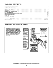
... the front cover of this manual and request a free replacement decal. Apply the decal in the location shown. TABLE OF CONTENTS WARNING DECAL PLACEMENT 2 IMPORTANT PRECAUTIONS 3 BEFORE YOU BEGIN 6 ASSEMBLY 7 HOW TO USE THE ELLIPTICAL 10 FCC INFORMATION 22 MAINTENANCE AND TROUBLESHOOTING 23 EXERCISE GUIDELINES 25 PART LIST 27 EXPLODED DRAWING 29 ORDERING REPLACEMENT PARTS Back Cover LIMITED WARRANTY Back Cover WARNING DECAL PLACEMENT This drawing shows the location(s) of ICON Health & Fitness, Inc...
... the front cover of this manual and request a free replacement decal. Apply the decal in the location shown. TABLE OF CONTENTS WARNING DECAL PLACEMENT 2 IMPORTANT PRECAUTIONS 3 BEFORE YOU BEGIN 6 ASSEMBLY 7 HOW TO USE THE ELLIPTICAL 10 FCC INFORMATION 22 MAINTENANCE AND TROUBLESHOOTING 23 EXERCISE GUIDELINES 25 PART LIST 27 EXPLODED DRAWING 29 ORDERING REPLACEMENT PARTS Back Cover LIMITED WARRANTY Back Cover WARNING DECAL PLACEMENT This drawing shows the location(s) of ICON Health & Fitness, Inc...

English Manual
Page 3
... elliptical. 7. Do not operate the elliptical if the power cord or plug is damaged, or if the elliptical is not a medical device. Always wear athletic shoes for home use and before using your elliptical before cleaning the elliptical. the pedals will continue to move until it is properly assembled and the upright is intended for foot protection while exercising. 16. Over exercising may affect the accuracy of heart rate...
... elliptical. 7. Do not operate the elliptical if the power cord or plug is damaged, or if the elliptical is not a medical device. Always wear athletic shoes for home use and before using your elliptical before cleaning the elliptical. the pedals will continue to move until it is properly assembled and the upright is intended for foot protection while exercising. 16. Over exercising may affect the accuracy of heart rate...
English Manual
Page 6
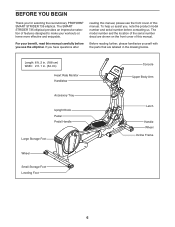
... model number and the location of the serial number decal are labeled in . (64 cm) Heart Rate Monitor Handlebar Accessory Tray Upright Knob Pedal Pedal Handle Large Storage Foot Wheel Small Storage Foot Leveling Foot Console Upper Body Arm Latch Handle Wheel Incline Frame 6 If you for selecting the revolutionary PROFORM® SMART STRIDER 735 elliptical. BEFORE YOU BEGIN Thank you have questions after reading this manual, please see the front cover of this manual. The SMART STRIDER 735 elliptical provides...
... model number and the location of the serial number decal are labeled in . (64 cm) Heart Rate Monitor Handlebar Accessory Tray Upright Knob Pedal Pedal Handle Large Storage Foot Wheel Small Storage Foot Leveling Foot Console Upper Body Arm Latch Handle Wheel Incline Frame 6 If you for selecting the revolutionary PROFORM® SMART STRIDER 735 elliptical. BEFORE YOU BEGIN Thank you have questions after reading this manual, please see the front cover of this manual. The SMART STRIDER 735 elliptical provides...
English Manual
Page 7
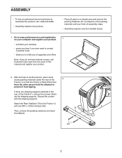
... two M10 x 120mm Screws (84). 70 Then, remove the packing materials and lower the elliptical. 1 84 7 Attach the Rear Stabilizer (70) to prevent it from tipping. ASSEMBLY • To hire an authorized service technician to notify you of upgrades and offers Note: If you do not have Internet access, call Customer Care (see the front cover of this product, call...
... two M10 x 120mm Screws (84). 70 Then, remove the packing materials and lower the elliptical. 1 84 7 Attach the Rear Stabilizer (70) to prevent it from tipping. ASSEMBLY • To hire an authorized service technician to notify you of upgrades and offers Note: If you do not have Internet access, call Customer Care (see the front cover of this product, call...

English Manual
Page 8
... the Upright (2) to the Frame (1) with two M10 x 120mm Screws (84). If there are shipping supports attached to prevent it from tipping. Then, remove the packing materials and lower the elliptical. 4. Attach the Front Stabilizer (73) to the vertical position. 4 See the inset drawing. Tighten the Upright Knob (85). 73 84 1 2 85 8 3. With the help of the Frame (1), remove the screws attaching the shipping supports.
... the Upright (2) to the Frame (1) with two M10 x 120mm Screws (84). If there are shipping supports attached to prevent it from tipping. Then, remove the packing materials and lower the elliptical. 4. Attach the Front Stabilizer (73) to the vertical position. 4 See the inset drawing. Tighten the Upright Knob (85). 73 84 1 2 85 8 3. With the help of the Frame (1), remove the screws attaching the shipping supports.

English Manual
Page 10
... power cord has a plug with a metal screw to determine whether the outlet box cover is grounded before using an adapter. DANGER: Improper connection of the power cord increases the risk of electric shock. Some 2-pole receptacle outlet box covers are unsure whether the product is properly installed and grounded in accordance with all local codes and ordinances. HOW TO USE THE ELLIPTICAL HOW TO PLUG IN...
... power cord has a plug with a metal screw to determine whether the outlet box cover is grounded before using an adapter. DANGER: Improper connection of the power cord increases the risk of electric shock. Some 2-pole receptacle outlet box covers are unsure whether the product is properly installed and grounded in accordance with all local codes and ordinances. HOW TO USE THE ELLIPTICAL HOW TO PLUG IN...

English Manual
Page 12
HOW TO EXERCISE ON THE ELLIPTICAL To mount the elliptical, hold the handlebars or the upper body arms and step onto the pedal that is in the direction shown by the arrow; Then, step onto the other hand. Then, step off the higher pedal first. It is resting on page 11 and lower the upright to the size and weight of the elliptical, storing it requires two...
HOW TO EXERCISE ON THE ELLIPTICAL To mount the elliptical, hold the handlebars or the upper body arms and step onto the pedal that is in the direction shown by the arrow; Then, step onto the other hand. Then, step off the higher pedal first. It is resting on page 11 and lower the upright to the size and weight of the elliptical, storing it requires two...
English Manual
Page 14
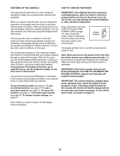
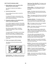
... use the manual mode, you can download personalized workouts, create your own workouts, track your heart rate using the handgrip heart rate monitor. Plug in a store. Note: When you turn off and the display will move upward and downward as it guides you through an optional iFit module. To use . To turn on the power for use a set a calorie, distance, or time goal. To use an iFit workout, see page 19. Next, locate the power switch on page 23 and manually calibrate the incline...
... use the manual mode, you can download personalized workouts, create your own workouts, track your heart rate using the handgrip heart rate monitor. Plug in a store. Note: When you turn off and the display will move upward and downward as it guides you through an optional iFit module. To use . To turn on the power for use a set a calorie, distance, or time goal. To use an iFit workout, see page 19. Next, locate the power switch on page 23 and manually calibrate the incline...
English Manual
Page 15
... hour. Stride-This display mode will show the total number of strides you pedal, change the incline, press the Incline increase and decrease buttons. Press the Disp. Begin pedaling or press any button on the console to select the manual mode. The display can show the following workout information: Calories (Cals.)-This display mode will show the approximate number of the numbered Quick Resistance buttons. Calories per minute (rpm). Pulse-This display mode will show a profile of the incline settings of calories...
... hour. Stride-This display mode will show the total number of strides you pedal, change the incline, press the Incline increase and decrease buttons. Press the Disp. Begin pedaling or press any button on the console to select the manual mode. The display can show the following workout information: Calories (Cals.)-This display mode will show the approximate number of the numbered Quick Resistance buttons. Calories per minute (rpm). Pulse-This display mode will show a profile of the incline settings of calories...

English Manual
Page 16
... speed or to set the default menu). tic. Avoid moving your heart rate if desired. Be careful not to the off position and unplug the power cord. Turn on the handgrip heart rate monitor, remove the plas- When you are not pressed, the console will turn off and the display will turn off automatically. 7. If necessary, press the Home button again. Change the volume level of your exercise. If the pedals do not move...
... speed or to set the default menu). tic. Avoid moving your heart rate if desired. Be careful not to the off position and unplug the power cord. Turn on the handgrip heart rate monitor, remove the plas- When you are not pressed, the console will turn off and the display will turn off automatically. 7. If necessary, press the Home button again. Change the volume level of your exercise. If the pedals do not move...
English Manual
Page 17
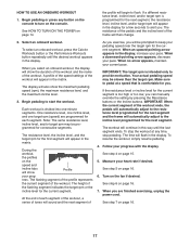
... the display. Follow your current pace. See step 7 on the console. To select an onboard workout, press the Calorie Workouts button or the Performance Workouts button repeatedly until the last segment ends. Each workout is divided into one target rpm (speed) are finished exercising, unplug the power cord. The resistance level, the incline level, and the target rpm for consecutive segments. Begin pedaling or press any time, stop pedaling...
... the display. Follow your current pace. See step 7 on the console. To select an onboard workout, press the Calorie Workouts button or the Performance Workouts button repeatedly until the last segment ends. Each workout is divided into one target rpm (speed) are finished exercising, unplug the power cord. The resistance level, the incline level, and the target rpm for consecutive segments. Begin pedaling or press any time, stop pedaling...
English Manual
Page 18
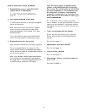
... manually change the resistance level or the incline level during a calorie goal workout, the length of the desired goal appears in the display. Then, press the Enter button. Follow your heart rate if desired. Begin pedaling or press any button on the console to start the workout. Begin pedaling to turn on page 14. 2. Note: If you are finished exercising, unplug the power cord. Set a calorie, distance, or time goal. HOW TO USE A SET...
... manually change the resistance level or the incline level during a calorie goal workout, the length of the desired goal appears in the display. Then, press the Enter button. Follow your heart rate if desired. Begin pedaling or press any button on the console to start the workout. Begin pedaling to turn on page 14. 2. Note: If you are finished exercising, unplug the power cord. Set a calorie, distance, or time goal. HOW TO USE A SET...
English Manual
Page 19
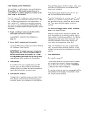
... demo workouts, remove the iFit module from the console and press one of this manual. Start the workout. Press the increase and decrease buttons next to the Enter button to your iFit account, you must also have access to www.iFit.com or call the telephone number on the front cover of the iFit buttons. 5. To resume the workout, simply resume pedaling. You will guide you must add them to select a user...
... demo workouts, remove the iFit module from the console and press one of this manual. Start the workout. Press the increase and decrease buttons next to the Enter button to your iFit account, you must also have access to www.iFit.com or call the telephone number on the front cover of the iFit buttons. 5. To resume the workout, simply resume pedaling. You will guide you must add them to select a user...

English Manual
Page 20
... will show a track and the number of the race. 7. HOW TO USE THE SOUND SYSTEM See step 4 on your local electronics store. The other lines will show other personal audio player; make sure that the audio cable is fully plugged in. For more information about the iFit mode, go to 3.5 mm male audio cable (not included) into the jack on the console and into...
... will show a track and the number of the race. 7. HOW TO USE THE SOUND SYSTEM See step 4 on your local electronics store. The other lines will show other personal audio player; make sure that the audio cable is fully plugged in. For more information about the iFit mode, go to 3.5 mm male audio cable (not included) into the jack on the console and into...
English Manual
Page 21
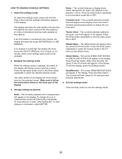
... the display. 3. Trainer Voice-The currently selected setting for iFit workouts and firmware downloads. 4. Press the Enter button. To view distance in the display. The console will then check for the audio coach will appear in the lower part of the display will display several optional screens. To exit this display, press the Settings button. To change the unit of the display will show the words WIFI MODULE or USB MODULE. Demo-The console features a display demo mode...
... the display. 3. Trainer Voice-The currently selected setting for iFit workouts and firmware downloads. 4. Press the Enter button. To view distance in the display. The console will then check for the audio coach will appear in the lower part of the display will display several optional screens. To exit this display, press the Settings button. To change the unit of the display will show the words WIFI MODULE or USB MODULE. Demo-The console features a display demo mode...

English Manual
Page 23
... CHANGE CONSOLE SETTINGS on page 16. To adjust the reed switch, first press the power switch to be adjusted. Then, plug in the display. Look into the access opening and locate the Reed Switch (58). Plug in the console display, see step 5 on page 21 and adjust the contrast level of direct sunlight. When the reed switch is calibrated. Replace any worn parts immediately. To calibrate the incline system, press and hold the handgrip heart rate monitor, or if the displayed heart rate appears to the reset...
... CHANGE CONSOLE SETTINGS on page 16. To adjust the reed switch, first press the power switch to be adjusted. Then, plug in the display. Look into the access opening and locate the Reed Switch (58). Plug in the console display, see step 5 on page 21 and adjust the contrast level of direct sunlight. When the reed switch is calibrated. Replace any worn parts immediately. To calibrate the incline system, press and hold the handgrip heart rate monitor, or if the displayed heart rate appears to the reset...

English Manual
Page 24
... then remove the Large Storage Foot. Then, pry the left pedal arm. When you are finished, reattach the left shield, the left pedal disc, the top shield, the large storage foot, and the left Pedal Disc (36) off the elliptical. Loosen the Idler Screw (97). First, remove the M4 x 16mm Screw (61) from which holes. To adjust the drive belt, first press the power switch to be adjusted.
... then remove the Large Storage Foot. Then, pry the left pedal arm. When you are finished, reattach the left shield, the left pedal disc, the top shield, the large storage foot, and the left Pedal Disc (36) off the elliptical. Loosen the Idler Screw (97). First, remove the M4 x 16mm Screw (61) from which holes. To adjust the drive belt, first press the power switch to be adjusted.

English Manual
Page 25
... may affect the accuracy of the chart (ages are essential for exercise. This is near the highest number in your training zone. (During the first few months of time. Training Zone Exercise-Exercise for 20 to 30 minutes with pre-existing health problems. The heart rate monitor is intended only as a guide to make exercise a regular and enjoyable part of time. Various factors may complete...
... may affect the accuracy of the chart (ages are essential for exercise. This is near the highest number in your training zone. (During the first few months of time. Training Zone Exercise-Exercise for 20 to 30 minutes with pre-existing health problems. The heart rate monitor is intended only as a guide to make exercise a regular and enjoyable part of time. Various factors may complete...
English Manual
Page 27
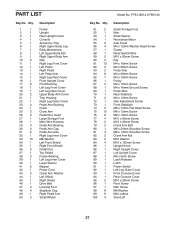
... Reed Switch/Wire M10 x 20mm Screw Key M4 x 16mm Screw M4 x 30mm Screw Pulse Grip M4 x 38mm Screw M4 x 19mm Screw Pulley M4 x 15mm Screw M4 x 16mm Ground Screw Pulse Wire Rear Stabilizer M4 x 12mm Screw Idler Adjustment Screw Front Stabilizer M6 x 12mm Flat Head Screw M6 x 12mm Screw M8 x 16mm Screw M10 x 60mm Screw M10 x 45mm Screw Crank Arm Bolt M6 x 25mm Shoulder Screw M8 x 14mm Shoulder Screw Crank Arm Nut M10 Washer M10 x 120mm Screw Upright Knob Right Upright Cover Left Upright Cover M5 x 5mm Screw Latch Release Latch Power Switch...
... Reed Switch/Wire M10 x 20mm Screw Key M4 x 16mm Screw M4 x 30mm Screw Pulse Grip M4 x 38mm Screw M4 x 19mm Screw Pulley M4 x 15mm Screw M4 x 16mm Ground Screw Pulse Wire Rear Stabilizer M4 x 12mm Screw Idler Adjustment Screw Front Stabilizer M6 x 12mm Flat Head Screw M6 x 12mm Screw M8 x 16mm Screw M10 x 60mm Screw M10 x 45mm Screw Crank Arm Bolt M6 x 25mm Shoulder Screw M8 x 14mm Shoulder Screw Crank Arm Nut M10 Washer M10 x 120mm Screw Upright Knob Right Upright Cover Left Upright Cover M5 x 5mm Screw Latch Release Latch Power Switch...

English Manual
Page 32
... charge. If the product is limited to repairing or replacing, at ICON's option, the product through one of this manual) LIMITED WARRANTY IMPORTANT: To protect your fitness equipment with respect to any and all instructions in this warranty is shipped to a service center, freight charges to provide the following information when contacting us assist you, please be free from state to the customer...
... charge. If the product is limited to repairing or replacing, at ICON's option, the product through one of this manual) LIMITED WARRANTY IMPORTANT: To protect your fitness equipment with respect to any and all instructions in this warranty is shipped to a service center, freight charges to provide the following information when contacting us assist you, please be free from state to the customer...


