
English Manual
Page 1
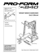
Patent Pending Sears, Roebuck and Co., Hoffman Estates, IL 60179 WEIGHT BENCH EXERCISER User's Manual Serial Number Decal (under seat) • Assembly • Adjustments • Part List and Drawing CAUTION Read all precautions and instructions in the space above for future reference. Write the serial number in this manual before using this manual for reference. Save this equipment. Model No. 831.153321 Serial No.
Patent Pending Sears, Roebuck and Co., Hoffman Estates, IL 60179 WEIGHT BENCH EXERCISER User's Manual Serial Number Decal (under seat) • Assembly • Adjustments • Part List and Drawing CAUTION Read all precautions and instructions in the space above for future reference. Write the serial number in this manual before using this manual for reference. Save this equipment. Model No. 831.153321 Serial No.
English Manual
Page 2
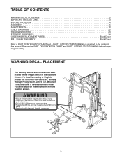
... BEGIN 4 ASSEMBLY 5 ADJUSTMENTS 19 CABLE DIAGRAMS 22 TROUBLESHOOTING 23 EXERCISE GUIDELINES 24 ORDERING REPLACEMENT PARTS Back Cover FULL 90-DAY WARRANTY Back Cover Note: A PART IDENTIFICATION CHART and a PART LIST/EXPLODED DRAWING is missing or illegible, please call toll-free 1-800-999-3756, Monday through Friday, 6 a.m. If a decal is attached in the locations shown. Place the decal on the weight bench in the center of this manual. Remove the PART IDENTIFICATION CHART and PART LIST/EXPLODED...
... BEGIN 4 ASSEMBLY 5 ADJUSTMENTS 19 CABLE DIAGRAMS 22 TROUBLESHOOTING 23 EXERCISE GUIDELINES 24 ORDERING REPLACEMENT PARTS Back Cover FULL 90-DAY WARRANTY Back Cover Note: A PART IDENTIFICATION CHART and a PART LIST/EXPLODED DRAWING is missing or illegible, please call toll-free 1-800-999-3756, Monday through Friday, 6 a.m. If a decal is attached in the locations shown. Place the decal on the weight bench in the center of this manual. Remove the PART IDENTIFICATION CHART and PART LIST/EXPLODED...
English Manual
Page 3
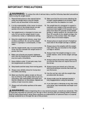
... that the set both safety spotters at least every two years. 11. Sears assumes no responsibility for home use only. Make sure that the cables are adequately informed of all instructions in any exercise program, consult your bench out of the way when performing an exercise that does not require the use the bench. 19. Cover the floor beneath the weight bench to support a maximum user weight of 300...
... that the set both safety spotters at least every two years. 11. Sears assumes no responsibility for home use only. Make sure that the cables are adequately informed of all instructions in any exercise program, consult your bench out of the way when performing an exercise that does not require the use the bench. 19. Cover the floor beneath the weight bench to support a maximum user weight of 300...
English Manual
Page 4
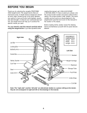
... Lat Bar Locking Bar Butterfly Arm Guide Bar ASSEMBLED DIMENSIONS: Height: 84 in . For your cardiovascular system, the weight bench will help us assist you, please note the product model number and serial number before using the weight bench. Before reading further, please review the drawing below and familiarize yourself with the parts that are determined relative to develop every major muscle group of the body. Width: 84 in the manual...
... Lat Bar Locking Bar Butterfly Arm Guide Bar ASSEMBLED DIMENSIONS: Height: 84 in . For your cardiovascular system, the weight bench will help us assist you, please note the product model number and serial number before using the weight bench. Before reading further, please review the drawing below and familiarize yourself with the parts that are determined relative to develop every major muscle group of the body. Width: 84 in the manual...
English Manual
Page 5
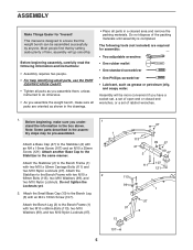
... Bench Leg (3) with two M10 x 92mm Carriage Bolts (111) and two M10 Nylon Locknuts (97). Attach the Bench Leg (3) to ensure that by anyone. The following information and instructions: • Assembly requires two people. • For help identifying small parts, use the PART IDENTIFICATION CHART. • Tighten all parts as you assemble them, unless instructed to do otherwise. • As you assemble the weight bench, make sure you have a socket set, a set...
... Bench Leg (3) with two M10 x 92mm Carriage Bolts (111) and two M10 Nylon Locknuts (97). Attach the Bench Leg (3) to ensure that by anyone. The following information and instructions: • Assembly requires two people. • For help identifying small parts, use the PART IDENTIFICATION CHART. • Tighten all parts as you assemble them, unless instructed to do otherwise. • As you assemble the weight bench, make sure you have a socket set, a set...
English Manual
Page 6
... Bench 3 Frame (1) with an M8 x 58mm Bolt (106), two M8 Washers (100), a 10mm Spacer (30), and an M8 Nylon Locknut (96). Press a 25mm Round Outer Cap (94) onto the Weight Tube (25). Do not overtighten the Screw. 1 97 11 27 Lubricate 110 5. Do not tighten the Locknuts yet. 112 99 99 112 97 97 7 6 Lubricate an M10 x 68mm Bolt...
... Bench 3 Frame (1) with an M8 x 58mm Bolt (106), two M8 Washers (100), a 10mm Spacer (30), and an M8 Nylon Locknut (96). Press a 25mm Round Outer Cap (94) onto the Weight Tube (25). Do not overtighten the Screw. 1 97 11 27 Lubricate 110 5. Do not tighten the Locknuts yet. 112 99 99 112 97 97 7 6 Lubricate an M10 x 68mm Bolt...
English Manual
Page 7
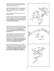
...; Attach the Seat (15) to pivot easily. 7. Make sure that the M10 x 62mm Flat Head Screw (27) is under the Adjustment Lever (11). Insert the Backrest Bracket (7) through the slot in steps 1 and 5. 6 97 99 8 27 1 7 11 7 99 109 Lubricate 14 8 8. Tighten the four M10 Nylon Locknuts (97) used in the Bench Frame (1) and under the Backrest Bracket arm. Lubricate an...
...; Attach the Seat (15) to pivot easily. 7. Make sure that the M10 x 62mm Flat Head Screw (27) is under the Adjustment Lever (11). Insert the Backrest Bracket (7) through the slot in steps 1 and 5. 6 97 99 8 27 1 7 11 7 99 109 Lubricate 14 8 8. Tighten the four M10 Nylon Locknuts (97) used in the Bench Frame (1) and under the Backrest Bracket arm. Lubricate an...
English Manual
Page 10
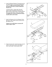
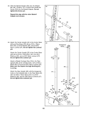
Using a rubber mallet, tap the left Rack Foot (46) into an adjustment hole near the bottom of the screw holes. Assemble the Left Spotter Hook (54) and a Safety Spotter (52) in the same manner. 17. Always set both Safety Spotters (52) at the same height. 18. Do not tighten the Locknuts ... with an M4 x 16mm Screw (107) and an M10 x 19mm Screw (118). Do not tighten the Locknuts yet. Attach a Base Cap (47) to the indicated Upright (36, 69). Slide each Barbell Glider (51, 123) onto the Guide Bar (41) next to the Right Base (34) with three M10 x 68mm Bolts (113), three M10 Washers ...
Using a rubber mallet, tap the left Rack Foot (46) into an adjustment hole near the bottom of the screw holes. Assemble the Left Spotter Hook (54) and a Safety Spotter (52) in the same manner. 17. Always set both Safety Spotters (52) at the same height. 18. Do not tighten the Locknuts ... with an M4 x 16mm Screw (107) and an M10 x 19mm Screw (118). Do not tighten the Locknuts yet. Attach a Base Cap (47) to the indicated Upright (36, 69). Slide each Barbell Glider (51, 123) onto the Guide Bar (41) next to the Right Base (34) with three M10 x 68mm Bolts (113), three M10 Washers ...
English Manual
Page 11
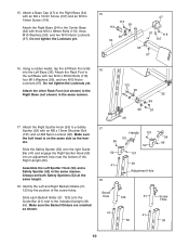
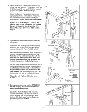
...) to the Left Upright (36) with two M10 x 91mm Bolts (116), four M10 Washers (99), and two M10 Nylon Locknuts (97). Make sure the Locking Bar 69 is oriented as shown. Thread a 1/4" x 14mm Screw (119) into a 123 56 set of holes in the same manner. 20. Press a Round Joint Bushing (74) into the Weight Stop and the hole...
...) to the Left Upright (36) with two M10 x 91mm Bolts (116), four M10 Washers (99), and two M10 Nylon Locknuts (97). Make sure the Locking Bar 69 is oriented as shown. Thread a 1/4" x 14mm Screw (119) into a 123 56 set of holes in the same manner. 20. Press a Round Joint Bushing (74) into the Weight Stop and the hole...
English Manual
Page 12
...Barbell Adapter (59) onto the Weight 23 Bar (55). Attach the Center Upright (37) to the Center Base (32) and Rear Base (33) with the other Barbell Adapter (not shown). 55 59 120 24. Attach a Weight Carriage Stop (70) to the Rear Base (33) with two M10 x 75mm Bolts ...(127), four M10 Washers (99), and two M10 Nylon Locknuts (97). Attach the Rear Upright (38), with the hexagonal holes on top. Thread a 1/4" x 9.5mm Allen Head Set Screw (120) into the Barbell Adapter...
...Barbell Adapter (59) onto the Weight 23 Bar (55). Attach the Center Upright (37) to the Center Base (32) and Rear Base (33) with the other Barbell Adapter (not shown). 55 59 120 24. Attach a Weight Carriage Stop (70) to the Rear Base (33) with two M10 x 75mm Bolts ...(127), four M10 Washers (99), and two M10 Nylon Locknuts (97). Attach the Rear Upright (38), with the hexagonal holes on top. Thread a 1/4" x 9.5mm Allen Head Set Screw (120) into the Barbell Adapter...
English Manual
Page 14
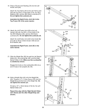
... (42) to the Rear Top 28 Frame (39) with grease. Tighten the 1/4" x 14mm Screws (119) used in step 22 and the 1/4" x 9.5mm Allen Head Set Screws (120) used in the inset drawing. Locate the Butterfly Cable (83). Do not tighten the Locknuts yet. Tighten all of the Arm is behind the indicated bracket on the Butterfly Frame (42) with two M10 x 78mm Bolts (110), two...
... (42) to the Rear Top 28 Frame (39) with grease. Tighten the 1/4" x 14mm Screws (119) used in step 22 and the 1/4" x 9.5mm Allen Head Set Screws (120) used in the inset drawing. Locate the Butterfly Cable (83). Do not tighten the Locknuts yet. Tighten all of the Arm is behind the indicated bracket on the Butterfly Frame (42) with two M10 x 78mm Bolts (110), two...
English Manual
Page 18
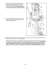
... Locknut; Make sure that the cables move smoothly, find and correct the problem. If there is used. Attach the Butterfly Backrest (80) to remove it by tightening the cables. If one of this manual for proper cable routing. 44. See TROUBLESHOOTING on page 23. 18 Attach the Low Cable (82) inside the Rear Base 44 (33) with two M6 x 72mm Screws (105) and two M6 Washers...
... Locknut; Make sure that the cables move smoothly, find and correct the problem. If there is used. Attach the Butterfly Backrest (80) to remove it by tightening the cables. If one of this manual for proper cable routing. 44. See TROUBLESHOOTING on page 23. 18 Attach the Low Cable (82) inside the Rear Base 44 (33) with two M6 x 72mm Screws (105) and two M6 Washers...
English Manual
Page 19
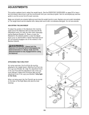
... be attached to the weight bench. Tighten the Curl Knob (29) into the Leg Lever Bracket (5). Make sure all parts are properly tightened each exercise. Do not use solvents. ment Lever so that the M10 x 62mm Flat Head Screw (27 [not shown]) engages one hand and lift the Adjustment Lever (11) with the adjustment hole in the Leg Lever Bracket. Fully tighten the Knob. The weight bench can...
... be attached to the weight bench. Tighten the Curl Knob (29) into the Leg Lever Bracket (5). Make sure all parts are properly tightened each exercise. Do not use solvents. ment Lever so that the M10 x 62mm Flat Head Screw (27 [not shown]) engages one hand and lift the Adjustment Lever (11) with the adjustment hole in the Leg Lever Bracket. Fully tighten the Knob. The weight bench can...
English Manual
Page 20
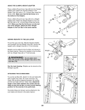
... Chain between the Lat Bar and the Lat Cable with a 1/4" x 9.5mm Allen Head Set Screw (120). Make sure that the Set Screw is in the correct starting position for the exercise to the Curl Bar (not shown) in the same manner. Weights can be performed. USING THE OLYMPIC WEIGHT ADAPTER Press a 48mm Round Inner Cap (23) into a Weight Adapter (60). Secure the weights with a Cable Clip (122). Adjust the length of...
... Chain between the Lat Bar and the Lat Cable with a 1/4" x 9.5mm Allen Head Set Screw (120). Make sure that the Set Screw is in the correct starting position for the exercise to the Curl Bar (not shown) in the same manner. Weights can be performed. USING THE OLYMPIC WEIGHT ADAPTER Press a 48mm Round Inner Cap (23) into a Weight Adapter (60). Secure the weights with a Cable Clip (122). Adjust the length of...
English Manual
Page 21
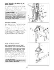
...Uprights. (Always start an exercise with the Large Weight Clips (77). USING THE LOCKING BAR Before starting an exercise, position the Safety Spotters (52) in the correct position for the exercise. Weight 59 77 Weight 77 71 69 123 56 MOVING THE SAFETY SPOTTERS Before starting an exercise, position the Locking Bar... grip the Locking Bar (56) with the Large Weight Clips (77). To move the Safety Spotters (52) to move during the exercise.) WARNING: Always set both hands. Turn the Locking Bar until the hooks engage the slots in the Uprights. Secure the weights with both Safety...
...Uprights. (Always start an exercise with the Large Weight Clips (77). USING THE LOCKING BAR Before starting an exercise, position the Safety Spotters (52) in the correct position for the exercise. Weight 59 77 Weight 77 71 69 123 56 MOVING THE SAFETY SPOTTERS Before starting an exercise, position the Locking Bar... grip the Locking Bar (56) with the Large Weight Clips (77). To move the Safety Spotters (52) to move during the exercise.) WARNING: Always set both hands. Turn the Locking Bar until the hooks engage the slots in the Uprights. Secure the weights with both Safety...
English Manual
Page 23
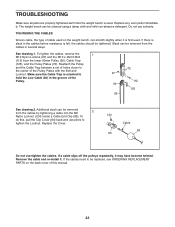
... re-install it may have become twisted. If a cable slips off the pulleys repeatedly, it . If the cables need to tighten the Locknut. Do not use pliers to be replaced, see ORDERING REPLACEMENT PARTS on the weight bench, can be tightened. If there is slack in the cables before resistance is used . To do this manual. 23 To tighten the cables, remove the 1 M10 Nylon Locknut (97) and the M10 x 45mm Bolt...
... re-install it may have become twisted. If a cable slips off the pulleys repeatedly, it . If the cables need to tighten the Locknut. Do not use pliers to be replaced, see ORDERING REPLACEMENT PARTS on the weight bench, can be tightened. If there is slack in the cables before resistance is used . To do this manual. 23 To tighten the cables, remove the 1 M10 Nylon Locknut (97) and the M10 x 45mm Bolt...
English Manual
Page 24
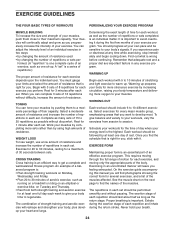
... appropriate parts of the body. On the exercise guide accompanying this manual you will continually adapt and grow as running on a treadmill or riding on an elliptical or exercise bike, on the next page to warm up. Select a moderate amount of resistance and increase the number of repetitions in two ways: • by changing the amount of resistance used • by changing the number of repetitions or sets...
... appropriate parts of the body. On the exercise guide accompanying this manual you will continually adapt and grow as running on a treadmill or riding on an elliptical or exercise bike, on the next page to warm up. Select a moderate amount of resistance and increase the number of repetitions in two ways: • by changing the amount of resistance used • by changing the number of repetitions or sets...
English Manual
Page 25
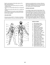
... work- Remember, the key to achieving the greatest results is an effective way to schedule and record your arms and legs. Abductor (outer thigh) H. Spinae Erectors (lower back) U. List the date, the exercises performed, the resistance used to increase flexibility. Pectoralis Major (chest) C. Gluteus Maximus (buttocks) W. Biceps (front of sets and repetitions completed. The chart on pages 26 and 27 of this manual...
... work- Remember, the key to achieving the greatest results is an effective way to schedule and record your arms and legs. Abductor (outer thigh) H. Spinae Erectors (lower back) U. List the date, the exercises performed, the resistance used to increase flexibility. Pectoralis Major (chest) C. Gluteus Maximus (buttocks) W. Biceps (front of sets and repetitions completed. The chart on pages 26 and 27 of this manual...
English Manual
Page 28
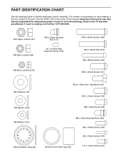
...part is the key number of this manual. If a part is not in the parts bag, check to identify small parts used in the center of the part, from the PART LIST in assembly. The number in parentheses by each drawing is missing, call toll-free 1-877-992-5999. Important: Some parts may have been pre-assembled...Shoulder Bolt (131) 1/4" x 9.5mm Allen Head Set Screw (120) M6 Nylon Locknut (124) M10 x 50mm Screw (108) M10 x 45mm Bolt (112) M6 x 38mm Screw (102) M10 x 25mm Screw (121) M10 Washer (99) M10 x 19mm Hex Head Bolt (132) M10 x 19mm Screw (118) M8 Washer (100) M8 x 16mm Screw (98...
...part is the key number of this manual. If a part is not in the parts bag, check to identify small parts used in the center of the part, from the PART LIST in assembly. The number in parentheses by each drawing is missing, call toll-free 1-877-992-5999. Important: Some parts may have been pre-assembled...Shoulder Bolt (131) 1/4" x 9.5mm Allen Head Set Screw (120) M6 Nylon Locknut (124) M10 x 50mm Screw (108) M10 x 45mm Bolt (112) M6 x 38mm Screw (102) M10 x 25mm Screw (121) M10 Washer (99) M10 x 19mm Hex Head Bolt (132) M10 x 19mm Screw (118) M8 Washer (100) M8 x 16mm Screw (98...
English Manual
Page 30
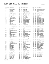
... Head Set Screw M10 x 25mm Screw Cable Clip Right Barbell Glider M6 Nylon Locknut Small Cable Trap M10 x 127mm Bolt M10 x 75mm Bolt M10 x 60mm Bolt M8 x 16mm Shoulder Bolt M10 x 72mm Hex Head Bolt M8 x 12mm Shoulder Bolt M10 x 19mm Hex Head Bolt User's Manual Exercise Guide Grease Pack Allen Wrench Note: "#" indicates a non-illustrated part. Description No. See the back cover of the user's manual for information about ordering replacement parts. PART LIST-Model No...
... Head Set Screw M10 x 25mm Screw Cable Clip Right Barbell Glider M6 Nylon Locknut Small Cable Trap M10 x 127mm Bolt M10 x 75mm Bolt M10 x 60mm Bolt M8 x 16mm Shoulder Bolt M10 x 72mm Hex Head Bolt M8 x 12mm Shoulder Bolt M10 x 19mm Hex Head Bolt User's Manual Exercise Guide Grease Pack Allen Wrench Note: "#" indicates a non-illustrated part. Description No. See the back cover of the user's manual for information about ordering replacement parts. PART LIST-Model No...


