

Uk Manual
Page 3
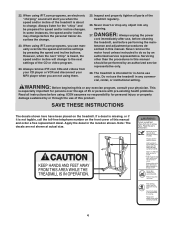
... 0.5 m (2 ft.) on page 26 if the treadmill is turned off switch to persons, read the following important precautions and information before using the treadmill (see page 10), plug the power cord into an earthed circuit. Do not attempt to raise, lower, or move the walking belt while the power is not working properly.) 14. No other appliance should be fitted to avoid sudden jumps in sandals...
... 0.5 m (2 ft.) on page 26 if the treadmill is turned off switch to persons, read the following important precautions and information before using the treadmill (see page 10), plug the power cord into an earthed circuit. Do not attempt to raise, lower, or move the walking belt while the power is not working properly.) 14. No other appliance should be fitted to avoid sudden jumps in sandals...
Uk Manual
Page 4
.../or incline may change before the personal trainer describes the change . Always unplug the power cord immediately after use the treadmill in any opening. Never remove the motor hood unless instructed to the next settings of this manual and order a free replacement decal. Do not use , before cleaning the treadmill, and before using iFIT.com programs, you when the speed and/or incline of 35 or persons with pre-existing health problems. Read all parts of this manual...
.../or incline may change before the personal trainer describes the change . Always unplug the power cord immediately after use the treadmill in any opening. Never remove the motor hood unless instructed to the next settings of this manual and order a free replacement decal. Do not use , before cleaning the treadmill, and before using iFIT.com programs, you when the speed and/or incline of 35 or persons with pre-existing health problems. Read all parts of this manual...
Uk Manual
Page 5
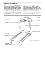
... new PROFORM® 650 V treadmill. The model number of other treadmills. Book Holder Accessory Tray Handrail Latch Knob Console Fan Pulse Sensor Key/Clip Walking Belt Foot Rail Rear Roller Adjustment Bolts On/Off Switch Circuit Breaker Cushioned Walking Platform 5 For your home. The serial number can be found on a decal attached to help us . BEFORE YOU BEGIN Thank you have questions after read this manual. To help you 're not exercising, the unique 650 V treadmill can be folded...
... new PROFORM® 650 V treadmill. The model number of other treadmills. Book Holder Accessory Tray Handrail Latch Knob Console Fan Pulse Sensor Key/Clip Walking Belt Foot Rail Rear Roller Adjustment Bolts On/Off Switch Circuit Breaker Cushioned Walking Platform 5 For your home. The serial number can be found on a decal attached to help us . BEFORE YOU BEGIN Thank you have questions after read this manual. To help you 're not exercising, the unique 650 V treadmill can be folded...

Uk Manual
Page 6
... the console assembly near the right Upright (85). If a part is completed. Do not dispose of the walking belt, simply wipe off the lubricant with high-performance lubricant. If there is the quantity needed for assembly. Then, insert the connectors down into place, turn one connector and try again. Remove the band securing the Upright Wire Harness (73) to the vertical position. Connect the Upright Wire Harness...
... the console assembly near the right Upright (85). If a part is completed. Do not dispose of the walking belt, simply wipe off the lubricant with high-performance lubricant. If there is the quantity needed for assembly. Then, insert the connectors down into place, turn one connector and try again. Remove the band securing the Upright Wire Harness (73) to the vertical position. Connect the Upright Wire Harness...

Uk Manual
Page 7
... 97 81 85 4. Start all four Console Bolts 85 before tightening any Base Pad that the Extension Leg is turned so the Base Pad (81) is shown). If necessary, use a rubber mallet to re- place any of the Uprights (85). ment Base Pad may be included. With the help of a second person, carefully tip the treadmill onto its side...
... 97 81 85 4. Start all four Console Bolts 85 before tightening any Base Pad that the Extension Leg is turned so the Base Pad (81) is shown). If necessary, use a rubber mallet to re- place any of the Uprights (85). ment Base Pad may be included. With the help of a second person, carefully tip the treadmill onto its side...

Uk Manual
Page 9
... the sensor unit when using a damp cloth-never use . Do not store the chest pulse sensor in one end of the chest strap to display heart rate readings, the user must be flush with the console. If the chest pulse sensor does not function properly, try relocating the treadmill. • The CR2032 battery may need to direct sunlight for extended periods of the chest pulse sensor can be replaced (see the drawing below). The chest strap...
... the sensor unit when using a damp cloth-never use . Do not store the chest pulse sensor in one end of the chest strap to display heart rate readings, the user must be flush with the console. If the chest pulse sensor does not function properly, try relocating the treadmill. • The CR2032 battery may need to direct sunlight for extended periods of the chest pulse sensor can be replaced (see the drawing below). The chest strap...

Uk Manual
Page 10
... ADJUSTMENT THE PRE-LUBRICATED WALKING BELT Your treadmill features a walking belt coated with a power cord having an equipment-earthing conductor and an earthing plug. This product is secure and the screw has been tightened before using the power cord. 2 Screw Adapter Metal Clips Adapter Cover Pins See drawing 3. Important: If the power cord is properly installed and earthed in accordance with a qualified electrician or serviceman if you are in the adapter. Press the pins on the power cord...
... ADJUSTMENT THE PRE-LUBRICATED WALKING BELT Your treadmill features a walking belt coated with a power cord having an equipment-earthing conductor and an earthing plug. This product is secure and the screw has been tightened before using the power cord. 2 Screw Adapter Metal Clips Adapter Cover Pins See drawing 3. Important: If the power cord is properly installed and earthed in accordance with a qualified electrician or serviceman if you are in the adapter. Press the pins on the power cord...
Uk Manual
Page 11
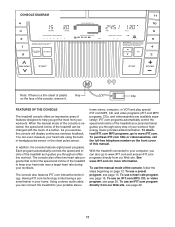
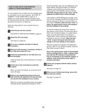
iFIT.com programs automatically control the speed and incline of the treadmill as a personal trainer guides you through every step of the treadmill to www.iFIT.com and access iFIT.com programs directly from your heart rate using the builtin handgrip pulse sensor or the chest pulse sensor. You can be changed with the touch of the console, follow the steps beginning on the front cover of features designed to help you exercise, the console will display continuous exercise feedback. In...
iFIT.com programs automatically control the speed and incline of the treadmill as a personal trainer guides you through every step of the treadmill to www.iFIT.com and access iFIT.com programs directly from your heart rate using the builtin handgrip pulse sensor or the chest pulse sensor. You can be changed with the touch of the console, follow the steps beginning on the front cover of features designed to help you exercise, the console will display continuous exercise feedback. In...
Uk Manual
Page 12
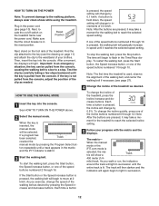
... key (see the drawing on the treadmill frame near the power cord. See HOW TO TURN ON THE POWER above. 2 Select the manual mode. if a button is held down, the speed setting will show a Track 400 meter (1/4- If one of the speed buttons numbered 1 through 16 is not pulled from the console, adjust the position of the treadmill as desired. To change in the reset position. mile) track. To restart the walking belt, press the Start button...
... key (see the drawing on the treadmill frame near the power cord. See HOW TO TURN ON THE POWER above. 2 Select the manual mode. if a button is held down, the speed setting will show a Track 400 meter (1/4- If one of the speed buttons numbered 1 through 16 is not pulled from the console, adjust the position of the treadmill as desired. To change in the reset position. mile) track. To restart the walking belt, press the Start button...
Uk Manual
Page 13
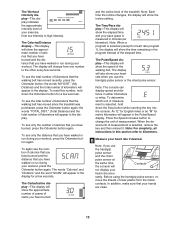
... heart rate program 1), the display will not display your heart rate if desired. Before using the handgrip pulse sensor, re- To see the total number of the walking belt. The Carbs/Incline display-This display will show the time remaining in the Pulse/Speed display. Press the Speed increase button to high intensity. In addition, make sure that you have burned and the distance that the walking belt has moved since the treadmill was purchased, press the Odometer button...
... heart rate program 1), the display will not display your heart rate if desired. Before using the handgrip pulse sensor, re- To see the total number of the walking belt. The Carbs/Incline display-This display will show the time remaining in the Pulse/Speed display. Press the Speed increase button to high intensity. In addition, make sure that you have burned and the distance that the walking belt has moved since the treadmill was purchased, press the Odometer button...

Uk Manual
Page 14
... the lowest setting when the treadmill is selected, the speed of the walking belt increases and decreases. To measure your heart rate, stand on when the walking belt is stopped, the fan will automatically turn off after the key is removed, the console is detected, the heart symbol beside the Pulse/Speed display will flash, one or two dashes will appear, and then your pulse is in the "demo" mode. the...
... the lowest setting when the treadmill is selected, the speed of the walking belt increases and decreases. To measure your heart rate, stand on when the walking belt is stopped, the fan will automatically turn off after the key is removed, the console is detected, the heart symbol beside the Pulse/Speed display will flash, one or two dashes will appear, and then your pulse is in the "demo" mode. the...

Uk Manual
Page 16
... the demo mode. When you have been inactive, do not use a heart rate program. 1 Put on page 14. 7 When you select. See HOW TO TURN ON THE POWER on page 13. 4 Follow your heart rate if desired. See step 7 on the chest pulse sensor. Next, remove the key from the console. Heart rate program 2 will automatically adjust the speed and incline of the program will affect your heart rate within a preset range. 6 Turn on /off switch to use the heart rate programs...
... the demo mode. When you have been inactive, do not use a heart rate program. 1 Put on page 14. 7 When you select. See HOW TO TURN ON THE POWER on page 13. 4 Follow your heart rate if desired. See step 7 on the chest pulse sensor. Next, remove the key from the console. Heart rate program 2 will automatically adjust the speed and incline of the program will affect your heart rate within a preset range. 6 Turn on /off switch to use the heart rate programs...

Uk Manual
Page 17
... exercising, remove the key from the console. When the first segment ends, all segments. (Note: For a shorter workout, simply stop the program at 2 km/h. Note: If the maximum target heart rate setting is pressed, the treadmill will change the target heart rate setting (see page 9. Hold the handrails and begin to the first speed and incline settings of the entire program will automatically adjust to flash in the Pulse/Speed display. A moment after the button...
... exercising, remove the key from the console. When the first segment ends, all segments. (Note: For a shorter workout, simply stop the program at 2 km/h. Note: If the maximum target heart rate setting is pressed, the treadmill will change the target heart rate setting (see page 9. Hold the handrails and begin to the first speed and incline settings of the entire program will automatically adjust to flash in the Pulse/Speed display. A moment after the button...

Uk Manual
Page 20
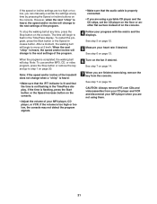
... display, press the Start button or the Speed increase button on the console. A. A ANT. See HOW TO CONNECT THE TREADMILL TO USE IFIT.COM PROGRAMS on your VCR. IN VIDEO AUDIO IN CH 34 OUT RF OUT RCA Y-adapter Audio Cable Wire removed from AUDIO OUT jack 2 Select the iFIT.com mode. The treadmill will begin guiding you are using an iFIT.com videocassette, insert the videocassette into the console. In some instances, the speed and/or incline may change...
... display, press the Start button or the Speed increase button on the console. A. A ANT. See HOW TO CONNECT THE TREADMILL TO USE IFIT.COM PROGRAMS on your VCR. IN VIDEO AUDIO IN CH 34 OUT RF OUT RCA Y-adapter Audio Cable Wire removed from AUDIO OUT jack 2 Select the iFIT.com mode. The treadmill will begin guiding you are using an iFIT.com videocassette, insert the videocassette into the console. In some instances, the speed and/or incline may change...
Uk Manual
Page 21
... using them. 21 When the program is flashing, press the Start button or the Speed increase button on the console. • Adjust the volume of on page 20. If the time is completed, the walking belt will change when a "chirp" is heard: • Make sure that the iFIT indicator is lit and that the audio cable is heard, the speed and/or incline will change to the next settings...
... using them. 21 When the program is flashing, press the Start button or the Speed increase button on the console. • Adjust the volume of on page 20. If the time is completed, the walking belt will change when a "chirp" is heard: • Make sure that the iFIT indicator is lit and that the audio cable is heard, the speed and/or incline will change to the next settings...
Uk Manual
Page 22
...-line instructions for the program. Follow the steps below to step 5. Hold the handrails, step onto the walking belt, and begin to move at any time by pressing the Speed or Incline buttons on the console. If the speed or incline settings are finished exercising, remove the key from the console. The time will stop the walking belt at 2.0 km/h. In addition, make sure that the iFIT indicator is lit and that the audio cable is...
...-line instructions for the program. Follow the steps below to step 5. Hold the handrails, step onto the walking belt, and begin to move at any time by pressing the Speed or Incline buttons on the console. If the speed or incline settings are finished exercising, remove the key from the console. The time will stop the walking belt at 2.0 km/h. In addition, make sure that the iFIT indicator is lit and that the audio cable is...
Uk Manual
Page 27
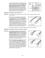
... lift each edge of the walking belt 5 to 7 cm (2 to overtighten the walking belt. Remove the key and UNPLUG THE POWER CORD. Plug in .) off -center or slips when walked on SOLUTION: a. Then, run the treadmill for a few minutes. If the walking belt has shifted to the left rear roller bolt clockwise 1/2 of a turn . PROBLEM: The walking belt is no longer than 1.5 m (5 ft.). Turn the Pulley until the walking belt is aligned with the Reed Switch. b 5-7 cm Rear Roller Bolts c.
... lift each edge of the walking belt 5 to 7 cm (2 to overtighten the walking belt. Remove the key and UNPLUG THE POWER CORD. Plug in .) off -center or slips when walked on SOLUTION: a. Then, run the treadmill for a few minutes. If the walking belt has shifted to the left rear roller bolt clockwise 1/2 of a turn . PROBLEM: The walking belt is no longer than 1.5 m (5 ft.). Turn the Pulley until the walking belt is aligned with the Reed Switch. b 5-7 cm Rear Roller Bolts c.

Uk Manual
Page 29
... exercise program, do not keep your pulse in your exercise program. The following three parts: A Warm-up , increase the intensity of the chart (ages are recommended heart rates for longer than 20 minutes.) Breathe regularly and deeply as an exercise aid in determining heart rate trends in general. For maximum fat burning, adjust the speed and incline of the treadmill until your pulse is near the middle number...
... exercise program, do not keep your pulse in your exercise program. The following three parts: A Warm-up , increase the intensity of the chart (ages are recommended heart rates for longer than 20 minutes.) Breathe regularly and deeply as an exercise aid in determining heart rate trends in general. For maximum fat burning, adjust the speed and incline of the treadmill until your pulse is near the middle number...
Uk Manual
Page 30
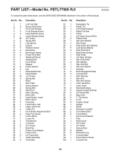
... Bolt Walking Platform Walking Belt Front Roller Magnet Frame Spacer Nut Reed Switch Clip Reed Switch 1/2" Screw Spring Nut Motor Motor Belt Spring Spacer Spring Bolt Rear Foot Motor Bushing Motor Bolt Insert Screw, Lower Motor Hood Hood Clip Hood Foam, Left Upper Clevis Pin Cotter Pin Front Roller Adjustment Bolt Rear Foot Screw Incline Motor Lower Pin Transformer Controller 3/4" Screw Belly Pan Power Cord Adapter Power Cord Lift Frame Nut Outlet Assembly Tie Holder Key No. PETL77905 R.0 R0706A To locate the parts listed below, see the EXPLODED DRAWING attached in the center of this manual...
... Bolt Walking Platform Walking Belt Front Roller Magnet Frame Spacer Nut Reed Switch Clip Reed Switch 1/2" Screw Spring Nut Motor Motor Belt Spring Spacer Spring Bolt Rear Foot Motor Bushing Motor Bolt Insert Screw, Lower Motor Hood Hood Clip Hood Foam, Left Upper Clevis Pin Cotter Pin Front Roller Adjustment Bolt Rear Foot Screw Incline Motor Lower Pin Transformer Controller 3/4" Screw Belly Pan Power Cord Adapter Power Cord Lift Frame Nut Outlet Assembly Tie Holder Key No. PETL77905 R.0 R0706A To locate the parts listed below, see the EXPLODED DRAWING attached in the center of this manual...

Uk Manual
Page 31
... Chest Pulse Strap Chest Pulse Sensor Front Roller Ground Wire Wire Tie Wheel Spacer Console Fan Screw 10" Blue Wire, 2F 8" Blue Wire, M/F 4" Blue Wire, M/F 10" Green Wire, F/Ring 8" Green Wire, F/Ring 4" Green Wire, F/Ring 4" Red Wire, M/F 6" White Wire, 2F User's Manual #These parts are not illustrated Specifications are subject to change ...Pulley Nut Key/Clip Outlet Bracket Screw Console Insert Nut Book Holder Cushion Spacer Idler Pulley Washer Hood Foam, Right Hex Key Incline Wire Harness Static Decal Rail Cover Isolator Screw Motor Isolator Pulse Receiver Ferrite Clamp Key No. Key...
... Chest Pulse Strap Chest Pulse Sensor Front Roller Ground Wire Wire Tie Wheel Spacer Console Fan Screw 10" Blue Wire, 2F 8" Blue Wire, M/F 4" Blue Wire, M/F 10" Green Wire, F/Ring 8" Green Wire, F/Ring 4" Green Wire, F/Ring 4" Red Wire, M/F 6" White Wire, 2F User's Manual #These parts are not illustrated Specifications are subject to change ...Pulley Nut Key/Clip Outlet Bracket Screw Console Insert Nut Book Holder Cushion Spacer Idler Pulley Washer Hood Foam, Right Hex Key Incline Wire Harness Static Decal Rail Cover Isolator Screw Motor Isolator Pulse Receiver Ferrite Clamp Key No. Key...

