Owner's Manual
Page 3
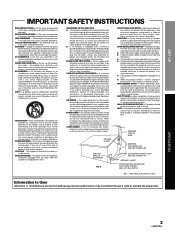
... corrode the cabinet. When installing an outside antenna or cable system is connected to replace your obsolete outlet. NATIONAL ELECTRICAL CODE Information to lightning and power-line surges. SET UP IMPOR TANT SAFETY INSTRUCTIONS READ INSTRUCTIONS - All the safety and operating instructions should not be blocked by the manufacturer, or sold with them , paying particular attention to cords at plugs, convenience receptacles, and the...
... corrode the cabinet. When installing an outside antenna or cable system is connected to replace your obsolete outlet. NATIONAL ELECTRICAL CODE Information to lightning and power-line surges. SET UP IMPOR TANT SAFETY INSTRUCTIONS READ INSTRUCTIONS - All the safety and operating instructions should not be blocked by the manufacturer, or sold with them , paying particular attention to cords at plugs, convenience receptacles, and the...
Owner's Manual
Page 4
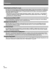
... require that the volume be made to a DVD player, Multi channel decoder equipped with 5.1 channel output to the DVD 5.1 channel input on this unit, you can enjoy the effects of quality surround sound even at low volumes. 5.1 Channel Input By connecting components equipped with 5.1 channel analog output jacks. 5 Channels of Independent Amplification This receiver incorporates 5 independent 80 watt power amplifiers which enable high quality playback of the power consumption in the (Dolby) Surround mode, decoding switches automatically according to music or watching movies...
... require that the volume be made to a DVD player, Multi channel decoder equipped with 5.1 channel output to the DVD 5.1 channel input on this unit, you can enjoy the effects of quality surround sound even at low volumes. 5.1 Channel Input By connecting components equipped with 5.1 channel analog output jacks. 5 Channels of Independent Amplification This receiver incorporates 5 independent 80 watt power amplifiers which enable high quality playback of the power consumption in the (Dolby) Surround mode, decoding switches automatically according to music or watching movies...
Owner's Manual
Page 5
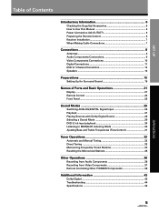
... Cable Connections 7 Connections 8 Antennas ...8 Audio Components Connections 9 Video Components Connections 10 Digital Connections 11 DVD 5.1 Channel Connection 12 Speakers 13 Preparations 15 Setting Up for Surround Sound 15 Names of Parts and Basic Operations 21 Display ...21 Remote Control 22 Front Panel 23 Sound Modes 25 Switching ANALOG/DIGITAL Signal Input 26 Playback ...27 Playing Sources with Dolby Digital Sound 28 Selecting a Sound Mode 29 DVD 5.1ch input playback 30 Listening in MIDNIGHT Listening Mode 30 Ajusting Bass and Treble Frequencies (Tone Control 31 Tuner...
... Cable Connections 7 Connections 8 Antennas ...8 Audio Components Connections 9 Video Components Connections 10 Digital Connections 11 DVD 5.1 Channel Connection 12 Speakers 13 Preparations 15 Setting Up for Surround Sound 15 Names of Parts and Basic Operations 21 Display ...21 Remote Control 22 Front Panel 23 Sound Modes 25 Switching ANALOG/DIGITAL Signal Input 26 Playback ...27 Playing Sources with Dolby Digital Sound 28 Selecting a Sound Mode 29 DVD 5.1ch input playback 30 Listening in MIDNIGHT Listening Mode 30 Ajusting Bass and Treble Frequencies (Tone Control 31 Tuner...
Owner's Manual
Page 9
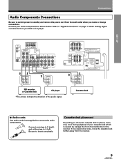
... or change connections. OPERA TION 9 SET UP Connections Audio Components Connections Be sure to switch power to connect the audio components. Refer to "Digital Connections" on where the cassette deck is placed, noise may occur during playback of the audio signal. L Connect red plugs to R (right) and white plugs to insert completely. R Be sure to L (left). ANTENNA DIGITAL IN PCM/ OPT 1 OPT 2 FM UNBAL 75Ω DVD 5.1 CH INPUT SURROUND L SUBWOOFER AM LOOP ANTENNA TO MONITOR TV CONTROL OUT IN VIDEO OUT...
... or change connections. OPERA TION 9 SET UP Connections Audio Components Connections Be sure to switch power to connect the audio components. Refer to "Digital Connections" on where the cassette deck is placed, noise may occur during playback of the audio signal. L Connect red plugs to R (right) and white plugs to insert completely. R Be sure to L (left). ANTENNA DIGITAL IN PCM/ OPT 1 OPT 2 FM UNBAL 75Ω DVD 5.1 CH INPUT SURROUND L SUBWOOFER AM LOOP ANTENNA TO MONITOR TV CONTROL OUT IN VIDEO OUT...

Owner's Manual
Page 10
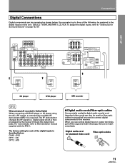
...DVD player (or LD player) 7 Audio/Video cords Use audio/video cords (not supplied) to connect the video components and a video cord to "Digital Connections" on page 11 when making digital connections from your video components as shown below. VIDEO Connect red plugs to R (right), L white plugs to L (left), and the yellow plugs to insert completely. Be sure to VIDEO. TV monitor INPUT VIDEO » Video deck « OUTPUT INPUT V V L L R R » ANTENNA DIGITAL IN PCM/ OPT 1 OPT 2 FM UNBAL 75Ω DVD 5.1 CH INPUT SURROUND L SUBWOOFER AM LOOP ANTENNA TO MONITOR TV CONTROL...
...DVD player (or LD player) 7 Audio/Video cords Use audio/video cords (not supplied) to connect the video components and a video cord to "Digital Connections" on page 11 when making digital connections from your video components as shown below. VIDEO Connect red plugs to R (right), L white plugs to L (left), and the yellow plugs to insert completely. Be sure to VIDEO. TV monitor INPUT VIDEO » Video deck « OUTPUT INPUT V V L L R R » ANTENNA DIGITAL IN PCM/ OPT 1 OPT 2 FM UNBAL 75Ω DVD 5.1 CH INPUT SURROUND L SUBWOOFER AM LOOP ANTENNA TO MONITOR TV CONTROL...
Owner's Manual
Page 11
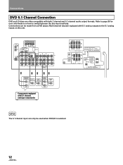
...Ω / SPEAKER ATTENTION: IMPEDANCE DE HAUT-PARLEURS 6Ω OU 8Ω ~ 16Ω / HAUT-PARLEUR CENTER PREOUT SUB WOOFER PREOUT CENTER SPEAKER RL SURROUND SPEAKERS CAUTION: ATTENTION: SEE INSTRUCTION SE REPOTER AU MANUAL MODE D'EMPLON 8~16Ω / SPEAKER 8~16Ω / HAUT- The factory setting for Surround Sound" on this receiver. When you use optical digital input or output terminals, pull off the caps and insert the plugs. The RF demodulator changes the RF signal to a digital signal which is...
...Ω / SPEAKER ATTENTION: IMPEDANCE DE HAUT-PARLEURS 6Ω OU 8Ω ~ 16Ω / HAUT-PARLEUR CENTER PREOUT SUB WOOFER PREOUT CENTER SPEAKER RL SURROUND SPEAKERS CAUTION: ATTENTION: SEE INSTRUCTION SE REPOTER AU MANUAL MODE D'EMPLON 8~16Ω / SPEAKER 8~16Ω / HAUT- The factory setting for Surround Sound" on this receiver. When you use optical digital input or output terminals, pull off the caps and insert the plugs. The RF demodulator changes the RF signal to a digital signal which is...
Owner's Manual
Page 12
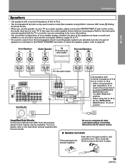
... INPUT SURROUND L SUBWOOFER AM LOOP ANTENNA TO MONITOR TV CONTROL OUT IN VIDEO OUT IN IN PCM/ COAX R CENTER IN OUT IN IN OUT IN IN L IN OUT VIDEO IN OUT L R R PLAY REC MD/TAPE 1 PLAY REC TV/ DVD/ CD TAPE 2 MONITOR SAT LD DVD 5.1 CH FRONT VCR » » » »» SURROUND OUTPUT L CENTER SUB WOOFER FRONT OUTPUT L VIDEO OUT R R Components equipped with both 2 channel and 5.1 channel audio output formats. Connections DVD 5.1 Channel Connection DVD and LD discs are often compatible with 5.1 channel analogue output jacks...
... INPUT SURROUND L SUBWOOFER AM LOOP ANTENNA TO MONITOR TV CONTROL OUT IN VIDEO OUT IN IN PCM/ COAX R CENTER IN OUT IN IN OUT IN IN L IN OUT VIDEO IN OUT L R R PLAY REC MD/TAPE 1 PLAY REC TV/ DVD/ CD TAPE 2 MONITOR SAT LD DVD 5.1 CH FRONT VCR » » » »» SURROUND OUTPUT L CENTER SUB WOOFER FRONT OUTPUT L VIDEO OUT R R Components equipped with both 2 channel and 5.1 channel audio output formats. Connections DVD 5.1 Channel Connection DVD and LD discs are often compatible with 5.1 channel analogue output jacks...
Owner's Manual
Page 13
... are selected, but less than 8 Ω, set the IMPEDANCE SELECTOR to secure the wire in place. 3/8 in this manual may be used in stereo mode (Not available during DVD 5.1 channel, DSP mode, (Dolby) Surround mode). • When you use the speaker on your TV as the center speaker) Surround Speakers SL SR SET UP OPERA TION (To the audio input) ANTENNA DIGITAL IN PCM/ OPT 1 OPT 2 FM UNBAL 75Ω DVD 5.1 CH INPUT SURROUND L SUBWOOFER AM LOOP ANTENNA TO MONITOR TV CONTROL OUT IN VIDEO...
... are selected, but less than 8 Ω, set the IMPEDANCE SELECTOR to secure the wire in place. 3/8 in this manual may be used in stereo mode (Not available during DVD 5.1 channel, DSP mode, (Dolby) Surround mode). • When you use the speaker on your TV as the center speaker) Surround Speakers SL SR SET UP OPERA TION (To the audio input) ANTENNA DIGITAL IN PCM/ OPT 1 OPT 2 FM UNBAL 75Ω DVD 5.1 CH INPUT SURROUND L SUBWOOFER AM LOOP ANTENNA TO MONITOR TV CONTROL OUT IN VIDEO...
Owner's Manual
Page 15
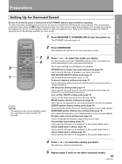
...which frequencies will be assigned to the optical digital input 2. 4 Press % or fi to the sub woofer or "Large" speakers. Optical digital input 2 setting (page 19) Use to specify the input to be sent to select the setting you change the placement of this unit on (The STANDBY indicator goes out) before operating. TUNER MPX DIRECT CLASS .ACCESS DVD 1 2 3 LD 4 5 6 TV CONTROL TEST TONE 7 8 9 SURROUND ATT. 0 CD DISC FUNCTION DSP MODE MUTING CHANNEL SELECT LEVEL RECEIVER STANDBY/ON EFFECT MASTER VOLUME Î AV MULTI-CHANNEL RECEIVER REMOTE CONTROL UNIT...
...which frequencies will be assigned to the optical digital input 2. 4 Press % or fi to the sub woofer or "Large" speakers. Optical digital input 2 setting (page 19) Use to specify the input to be sent to select the setting you change the placement of this unit on (The STANDBY indicator goes out) before operating. TUNER MPX DIRECT CLASS .ACCESS DVD 1 2 3 LD 4 5 6 TV CONTROL TEST TONE 7 8 9 SURROUND ATT. 0 CD DISC FUNCTION DSP MODE MUTING CHANNEL SELECT LEVEL RECEIVER STANDBY/ON EFFECT MASTER VOLUME Î AV MULTI-CHANNEL RECEIVER REMOTE CONTROL UNIT...
Owner's Manual
Page 16
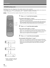
...the surround speaker. SIGNAL SELECT ANALOG SP A ∗ • Select "S " if you did not connect surround speakers. FREQ. memo If the cone size of your speaker is "L (Large)") • Select "SL" if your speakers will reproduce bass frequencies effectively. • Select "SS" to send bass frequencies to previous setting. 16 TUNER MPX DIRECT CLASS .ACCESS DVD 1 2 3 LD 4 5 6 TV CONTROL TEST TONE 7 8 9 SURROUND ATT. 0 CD DISC FUNCTION DSP MODE MUTING CHANNEL SELECT LEVEL RECEIVER STANDBY/ON EFFECT MASTER VOLUME AV MULTI-CHANNEL RECEIVER REMOTE CONTROL...
...the surround speaker. SIGNAL SELECT ANALOG SP A ∗ • Select "S " if you did not connect surround speakers. FREQ. memo If the cone size of your speaker is "L (Large)") • Select "SL" if your speakers will reproduce bass frequencies effectively. • Select "SS" to send bass frequencies to previous setting. 16 TUNER MPX DIRECT CLASS .ACCESS DVD 1 2 3 LD 4 5 6 TV CONTROL TEST TONE 7 8 9 SURROUND ATT. 0 CD DISC FUNCTION DSP MODE MUTING CHANNEL SELECT LEVEL RECEIVER STANDBY/ON EFFECT MASTER VOLUME AV MULTI-CHANNEL RECEIVER REMOTE CONTROL...
Owner's Manual
Page 18
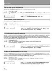
... (up to 30 steps). CENTER speaker distance setting mode Normally as the Center speaker is placed directly in front in the listening room, it is output through the sub woofer. Like the CENTER speaker position, the SURROUND speakers may be heard before the Front speakers. SIGNAL SP A SELECT ANALOG Press % or fi to select low cut filter cannot be set. • One step equals about 1 foot (30 cm). SIGNAL SP A SELECT ANALOG Press % or fi...
... (up to 30 steps). CENTER speaker distance setting mode Normally as the Center speaker is placed directly in front in the listening room, it is output through the sub woofer. Like the CENTER speaker position, the SURROUND speakers may be heard before the Front speakers. SIGNAL SP A SELECT ANALOG Press % or fi to select low cut filter cannot be set. • One step equals about 1 foot (30 cm). SIGNAL SP A SELECT ANALOG Press % or fi...
Owner's Manual
Page 21
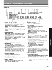
... ~! 1 SIGNAL SELECT indicators Light to indicate the type of a Dolby Digital signal. TUNED : Lights when a broadcast is on. 0 H.P indicator Lights when headphones are not present in all parts of the input signal. (available in ANALOG mode only) 5 Overload indicator When "ANALOG" is selected in . - LFE indicator LFE (Low Frequency Effects) indicator lights to show the channels being processed . OPERATION 21 DIGITAL : When the Dolby mode on the reciever is on (refer to "Remote Control", 9, Number buttons page 22) is being played back...
... ~! 1 SIGNAL SELECT indicators Light to indicate the type of a Dolby Digital signal. TUNED : Lights when a broadcast is on. 0 H.P indicator Lights when headphones are not present in all parts of the input signal. (available in ANALOG mode only) 5 Overload indicator When "ANALOG" is selected in . - LFE indicator LFE (Low Frequency Effects) indicator lights to show the channels being processed . OPERATION 21 DIGITAL : When the Dolby mode on the reciever is on (refer to "Remote Control", 9, Number buttons page 22) is being played back...
Owner's Manual
Page 22
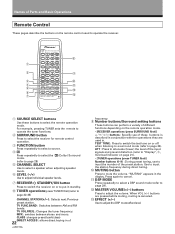
... to adjust the volume. TAPE BAND TV VOL. DSP MODE Press repeatedly to select a DSP sound mode (refer to page 29). = MASTER VOLUME(+/-) buttons Press to cancel. - Use to input the station frequency during direct tuning. 0 MUTING button Press to page 20). TV FUNC.BAND : Switches between stereo and mono. "MUTING" appears in standby. 8 TUNER operations(press TUNER first)(refer to operate the receiver. 1 2 3 4 5 6 7 SOURCE SELECT CD STANDBY/ON CHANNEL STATION TV FUNC. TV VOL.FREQ. :Changes the tuner frequency. FREQ. TEST TONE : Press to switch the test tone on...
... to adjust the volume. TAPE BAND TV VOL. DSP MODE Press repeatedly to select a DSP sound mode (refer to page 29). = MASTER VOLUME(+/-) buttons Press to cancel. - Use to input the station frequency during direct tuning. 0 MUTING button Press to page 20). TV FUNC.BAND : Switches between stereo and mono. "MUTING" appears in standby. 8 TUNER operations(press TUNER first)(refer to operate the receiver. 1 2 3 4 5 6 7 SOURCE SELECT CD STANDBY/ON CHANNEL STATION TV FUNC. TV VOL.FREQ. :Changes the tuner frequency. FREQ. TEST TONE : Press to switch the test tone on...
Owner's Manual
Page 23
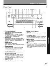
...Panel 1 2 3 4 56 7 8 9 0 - =~ !@# $ STANDBY STANDBY/ON VSX-D498 AUDIO/VIDEO MULTI-CHANNEL RECEIVER MPX CLASS MEMORY MODE - + STATION TUNING SELECT - + FREQUENCY DSP MODE SIGNAL SELECT MIDNIGHT PHONES SPEAKERS A B BASS TREBLE - + - + LOUDNESS DIRECT VCR DVD/LD DVD 5.1CH TV/SAT VIDEO CD FM/AM MD/TAPE 1 TAPE 2 MONITOR MASTER VOLUME DOWN UP VIDEO INPUT VIDEO L AUDIO R OPERATION % ^ & *( ) 1 STANDBY/ON button Press to switch the receiver on or put in standby. 2 STANDBY indicator Lights when the receiver is weak, selecting "MONO" will improve the sound...
...Panel 1 2 3 4 56 7 8 9 0 - =~ !@# $ STANDBY STANDBY/ON VSX-D498 AUDIO/VIDEO MULTI-CHANNEL RECEIVER MPX CLASS MEMORY MODE - + STATION TUNING SELECT - + FREQUENCY DSP MODE SIGNAL SELECT MIDNIGHT PHONES SPEAKERS A B BASS TREBLE - + - + LOUDNESS DIRECT VCR DVD/LD DVD 5.1CH TV/SAT VIDEO CD FM/AM MD/TAPE 1 TAPE 2 MONITOR MASTER VOLUME DOWN UP VIDEO INPUT VIDEO L AUDIO R OPERATION % ^ & *( ) 1 STANDBY/ON button Press to switch the receiver on or put in standby. 2 STANDBY indicator Lights when the receiver is weak, selecting "MONO" will improve the sound...
Owner's Manual
Page 24
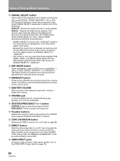
...modes to produce surround sound from the digital output, set SIGNAL SELECT to "ANALOG". @ DSP MODE button Press repeatedly to hear effective surround sound at low volume levels. When DIRECT is ON, Dolby, DSP, LOUDNESS and MIDNIGHT mode are input. (Dolby Digital decoding is switched automatically.) • SIGNAL SELECT is automatically adjusted according to the volume level. $ MASTER VOLUME After turning on the desired component, rotate to adjust the volume. % PHONES jack Connect headphones for higher fidelity to select the preset channel. Names of the signal being input. FREQUENCY...
...modes to produce surround sound from the digital output, set SIGNAL SELECT to "ANALOG". @ DSP MODE button Press repeatedly to hear effective surround sound at low volume levels. When DIRECT is ON, Dolby, DSP, LOUDNESS and MIDNIGHT mode are input. (Dolby Digital decoding is switched automatically.) • SIGNAL SELECT is automatically adjusted according to the volume level. $ MASTER VOLUME After turning on the desired component, rotate to adjust the volume. % PHONES jack Connect headphones for higher fidelity to select the preset channel. Names of the signal being input. FREQUENCY...
Owner's Manual
Page 28
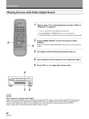
... receiver at the digital input jacks. TAPE BAND TV VOL. For more details, refer to a digital signal which is required. Sound Modes Playing Sources with the RFD-1. The RF demodulator changes the RF signal to the instruction manual supplied with Dolby Digital Sound 3 SOURCE SELECT CD STANDBY/ON CHANNEL STATION TV FUNC. TUNER MPX DIRECT CLASS .ACCESS DVD 1 2 3 LD 4 5 6 TV CONTROL TEST TONE 7 8 9 SURROUND ATT. 0 CD DISC FUNCTION DSP MODE MUTING CHANNEL SELECT LEVEL RECEIVER STANDBY/ON EFFECT MASTER VOLUME Î AV MULTI-CHANNEL RECEIVER REMOTE CONTROL...
... receiver at the digital input jacks. TAPE BAND TV VOL. For more details, refer to a digital signal which is required. Sound Modes Playing Sources with the RFD-1. The RF demodulator changes the RF signal to the instruction manual supplied with Dolby Digital Sound 3 SOURCE SELECT CD STANDBY/ON CHANNEL STATION TV FUNC. TUNER MPX DIRECT CLASS .ACCESS DVD 1 2 3 LD 4 5 6 TV CONTROL TEST TONE 7 8 9 SURROUND ATT. 0 CD DISC FUNCTION DSP MODE MUTING CHANNEL SELECT LEVEL RECEIVER STANDBY/ON EFFECT MASTER VOLUME Î AV MULTI-CHANNEL RECEIVER REMOTE CONTROL...
Owner's Manual
Page 29
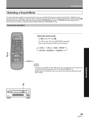
...TUNER MPX DIRECT CLASS .ACCESS DVD 1 2 3 LD 4 5 6 TV CONTROL TEST TONE 7 8 9 SURROUND ATT. 0 CD DISC FUNCTION DSP MODE MUTING CHANNEL SELECT LEVEL RECEIVER STANDBY/ON EFFECT MASTER VOLUME Î AV MULTI-CHANNEL RECEIVER REMOTE CONTROL UNIT Select the sound mode. • For (Dolby) \ Press • For DSP modes \ Press DSP MODE repeatedly Each press changes the DSP mode as follows: =HALL 1 = HALL 2 = JAZZ = DANCE SFC OFF+ THEATER 2 + THEATER 1 + EFFECT +/- If SPEAKERS B are used simultaneously with DSP modes. 2 OPERATION 29 Surrround operation 1 2 SOURCE SELECT...
...TUNER MPX DIRECT CLASS .ACCESS DVD 1 2 3 LD 4 5 6 TV CONTROL TEST TONE 7 8 9 SURROUND ATT. 0 CD DISC FUNCTION DSP MODE MUTING CHANNEL SELECT LEVEL RECEIVER STANDBY/ON EFFECT MASTER VOLUME Î AV MULTI-CHANNEL RECEIVER REMOTE CONTROL UNIT Select the sound mode. • For (Dolby) \ Press • For DSP modes \ Press DSP MODE repeatedly Each press changes the DSP mode as follows: =HALL 1 = HALL 2 = JAZZ = DANCE SFC OFF+ THEATER 2 + THEATER 1 + EFFECT +/- If SPEAKERS B are used simultaneously with DSP modes. 2 OPERATION 29 Surrround operation 1 2 SOURCE SELECT...
Owner's Manual
Page 32
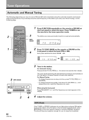
... select the tuner. DIRECT 3 The station you were previously tuned to is weak, press MPX MODE on the front panel to the tuner operation mode. 2 TV FUNC. TUNER MPX CLASS .ACCESS DVD 1 2 3 LD 4 5 6 TV CONTROL TEST TONE 7 8 9 MPX MODE SIGNAL SELECT ANALOG SP A dB SURROUND ATT. MPX Mode If the TUNED or STEREO indicators do not light when tuning an FM station, because the station is too far away or the broadcast signal is received automatically. SOURCE SELECT CD STANDBY/ON CHANNEL STATION 1 Press FUNCTION...
... select the tuner. DIRECT 3 The station you were previously tuned to is weak, press MPX MODE on the front panel to the tuner operation mode. 2 TV FUNC. TUNER MPX CLASS .ACCESS DVD 1 2 3 LD 4 5 6 TV CONTROL TEST TONE 7 8 9 MPX MODE SIGNAL SELECT ANALOG SP A dB SURROUND ATT. MPX Mode If the TUNED or STEREO indicators do not light when tuning an FM station, because the station is too far away or the broadcast signal is received automatically. SOURCE SELECT CD STANDBY/ON CHANNEL STATION 1 Press FUNCTION...
Owner's Manual
Page 36
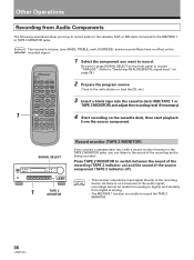
... signal. 1 SOURCE SELECT CD STANDBY/ON CHANNEL STATION TV FUNC. TAPE BAND TV VOL. Press TAPE 2 MONITOR to switch between the sound of the source component (TAPE 2 indicator off). Other Operations Recording from Audio Components The following operations show you want to record. TUNER MPX DIRECT CLASS .ACCESS DVD 1 2 3 LD 4 5 6 TV CONTROL TEST TONE 7 8 9 SURROUND ATT. 0 CD DISC FUNCTION DSP MODE MUTING CHANNEL SELECT LEVEL RECEIVER STANDBY/ON EFFECT MASTER VOLUME 1 Select the component you how to record audio to the cassette, DAT, or MD deck connected...
... signal. 1 SOURCE SELECT CD STANDBY/ON CHANNEL STATION TV FUNC. TAPE BAND TV VOL. Press TAPE 2 MONITOR to switch between the sound of the source component (TAPE 2 indicator off). Other Operations Recording from Audio Components The following operations show you want to record. TUNER MPX DIRECT CLASS .ACCESS DVD 1 2 3 LD 4 5 6 TV CONTROL TEST TONE 7 8 9 SURROUND ATT. 0 CD DISC FUNCTION DSP MODE MUTING CHANNEL SELECT LEVEL RECEIVER STANDBY/ON EFFECT MASTER VOLUME 1 Select the component you how to record audio to the cassette, DAT, or MD deck connected...

Owner's Manual
Page 43
... frequency range from 20 Hz to increase. For compact disc players and laser disc digital sounds, 16 bits are now available on Laser Discs record signals using Dolby Digital since 1992 has exceeded 300 and continues to 20 kHz and an independent Low Frequency Effect (LEF) channel. Additional Information Dolby Digital Dolby Digital is equipped with existing discs and players. of playback channels Playback channel structure 5.1 channels (Max.) 5.1 channels (Max.) Front Left, Front Right, Center, Surround Left, Surround Right, Sub Woofer Dolby Pro...
... frequency range from 20 Hz to increase. For compact disc players and laser disc digital sounds, 16 bits are now available on Laser Discs record signals using Dolby Digital since 1992 has exceeded 300 and continues to 20 kHz and an independent Low Frequency Effect (LEF) channel. Additional Information Dolby Digital Dolby Digital is equipped with existing discs and players. of playback channels Playback channel structure 5.1 channels (Max.) 5.1 channels (Max.) Front Left, Front Right, Center, Surround Left, Surround Right, Sub Woofer Dolby Pro...


