Owner's Manual
Page 1
AUDIO/VIDEO MULTI-CHANNEL RECEIVER VSX-D411 VSX-D511 Operating Instructions
AUDIO/VIDEO MULTI-CHANNEL RECEIVER VSX-D411 VSX-D511 Operating Instructions
Owner's Manual
Page 4
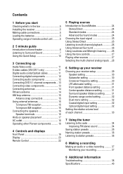
... 5 Installing the receiver 5 Making cable connections 5 Loading the batteries 5 Operating range of remote control unit 5 2 5 minute guide Introduction to home theater 6 Listening to Surround Sound 7 Using the Quick Setup 10 3 Connecting up Audio/Video cords 11 S-video cables (VSX-D511 only 11 Digital...To improve AM reception 15 Connecting the speakers 16 Speaker terminals 16 Hints on speaker placement 17 AC outlet 18 Operating other Pioneer components .......... 18 4 Controls and displays Front Panel 19 Display 20 Remote Control 22 5 Playing sources Introduction to Sound Modes...
... 5 Installing the receiver 5 Making cable connections 5 Loading the batteries 5 Operating range of remote control unit 5 2 5 minute guide Introduction to home theater 6 Listening to Surround Sound 7 Using the Quick Setup 10 3 Connecting up Audio/Video cords 11 S-video cables (VSX-D511 only 11 Digital...To improve AM reception 15 Connecting the speakers 16 Speaker terminals 16 Hints on speaker placement 17 AC outlet 18 Operating other Pioneer components .......... 18 4 Controls and displays Front Panel 19 Display 20 Remote Control 22 5 Playing sources Introduction to Sound Modes...
Owner's Manual
Page 5
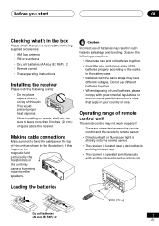
... SDTIERREECOT/ INPUT ATTLISFTELNDINIMGMMEORDE SSEIGLNEACLT MONITOR MIDNIGHT LOUDNESS TONE QUICK SETUP MULTI JOG AUDIO/VIDEO MULTI-CHANNEL MULTI JOG RECEIVER N∫m-Û.,, ENTER SINEPLUETCTOR DOWN MASTER VOLUME UP R • When installing on top of this unit...STANDARD SAUDRVARONCUNEDD SDTIERREECOT/ INPUT ATTLISFTELNDINIMGMMEORDE SSEIGLNEACLT MONITOR MIDNIGHT LOUDNESS TONE QUICK SETUP MULTI JOG AUDIO/VIDEO MULTI-CHANNEL MULTI JOG RECEIVER N∫m-Û.,, ENTER SINEPLUETCTOR DOWN MASTER VOLUME 30 UP R 23ft (7m) Dry cell batteries (AA size IEC ...
... SDTIERREECOT/ INPUT ATTLISFTELNDINIMGMMEORDE SSEIGLNEACLT MONITOR MIDNIGHT LOUDNESS TONE QUICK SETUP MULTI JOG AUDIO/VIDEO MULTI-CHANNEL MULTI JOG RECEIVER N∫m-Û.,, ENTER SINEPLUETCTOR DOWN MASTER VOLUME UP R • When installing on top of this unit...STANDARD SAUDRVARONCUNEDD SDTIERREECOT/ INPUT ATTLISFTELNDINIMGMMEORDE SSEIGLNEACLT MONITOR MIDNIGHT LOUDNESS TONE QUICK SETUP MULTI JOG AUDIO/VIDEO MULTI-CHANNEL MULTI JOG RECEIVER N∫m-Û.,, ENTER SINEPLUETCTOR DOWN MASTER VOLUME 30 UP R 23ft (7m) Dry cell batteries (AA size IEC ...
Owner's Manual
Page 6
This receiver will automatically decode Dolby Digital, DTS, or Dolby Surround DVD-Video discs, according to soundtracks. In most cases, you won't have to make changes for ... sound) when listening to your room, but may not be used to home theater systems that give you get from one disc, all of the receiver. DVD-Video has become the basic source material for realistic surround sound, but other possibilities (like you're in your speaker setup. Depending on page...
This receiver will automatically decode Dolby Digital, DTS, or Dolby Surround DVD-Video discs, according to soundtracks. In most cases, you won't have to make changes for ... sound) when listening to your room, but may not be used to home theater systems that give you get from one disc, all of the receiver. DVD-Video has become the basic source material for realistic surround sound, but other possibilities (like you're in your speaker setup. Depending on page...
Owner's Manual
Page 7
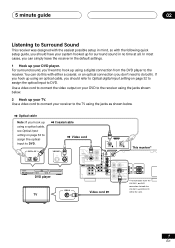
Use a video cord to connect your DVD player. In most cases, you can do both the VSX-D411 and VSX-D411S will be the same. 7 En Use a video cord to connect the video output on page 32 to assign the optical input to DVD. DIGITAL OUT ... VIDEO OUT S DVD IN / LD FRONT D V D 5.1CH REC INPUT CD-R IN / TAPE / MD ASSIGNABLE DIGITAL IN COAX OPT (DVD/LD) ¥ (TV/SAT) ¥ This receiver* VIDEO OUT STANDBY/ON 41 ¡¢ 0 7 8 Î 3 DVD PLAYER DVD player VIDEO IN TV IN Video cord MONITOR OUT SUB WOOFER PREOUT *The illustration...
Use a video cord to connect your DVD player. In most cases, you can do both the VSX-D411 and VSX-D411S will be the same. 7 En Use a video cord to connect the video output on page 32 to assign the optical input to DVD. DIGITAL OUT ... VIDEO OUT S DVD IN / LD FRONT D V D 5.1CH REC INPUT CD-R IN / TAPE / MD ASSIGNABLE DIGITAL IN COAX OPT (DVD/LD) ¥ (TV/SAT) ¥ This receiver* VIDEO OUT STANDBY/ON 41 ¡¢ 0 7 8 Î 3 DVD PLAYER DVD player VIDEO IN TV IN Video cord MONITOR OUT SUB WOOFER PREOUT *The illustration...
Owner's Manual
Page 8
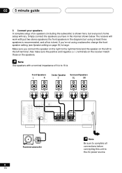
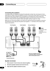
... with just two stereo speakers (the front speakers in the manner shown below. Make sure you connect the speaker on the right to large. The receiver will work with a nominal impedance of six speakers (including the subwoofer) is best. Front Speakers L R Center Speaker C Surround Speakers SL SR...Speaker setting on page 30) to the right terminal and the speaker on the speakers. Also make sure the positive and negative (+/-) terminals on the receiver match those on the left to 16 Ω. If you have in the diagram) but everyone's home setup will vary. A complete setup of...
... with just two stereo speakers (the front speakers in the manner shown below. Make sure you connect the speaker on the right to large. The receiver will work with a nominal impedance of six speakers (including the subwoofer) is best. Front Speakers L R Center Speaker C Surround Speakers SL SR...Speaker setting on page 30) to the right terminal and the speaker on the speakers. Also make sure the positive and negative (+/-) terminals on the receiver match those on the left to 16 Ω. If you have in the diagram) but everyone's home setup will vary. A complete setup of...
Owner's Manual
Page 9
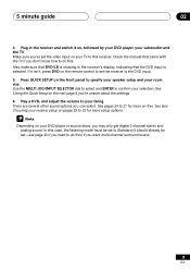
... switch it on this. If it isn't, press DVD on the remote control to set the receiver to the DVD input. 5 Press QUICK SETUP on the next page if you may only get digital ... and analog sound. See Using the Quick Setup on the front panel to your subwoofer and the TV. See also Choosing your receiver setup on your DVD player or source discs, you 're unsure about the settings. 6 Play a DVD, and adjust the ...mode must be set to do this) if you can select. 5 minute guide 02 4 Plug in the receiver's display, indicating that came with the TV if you 've set -see page 26 if you need to this...
... switch it on this. If it isn't, press DVD on the remote control to set the receiver to the DVD input. 5 Press QUICK SETUP on the next page if you may only get digital ... and analog sound. See Using the Quick Setup on the front panel to your subwoofer and the TV. See also Choosing your receiver setup on your DVD player or source discs, you 're unsure about the settings. 6 Play a DVD, and adjust the ...mode must be set to do this) if you can select. 5 minute guide 02 4 Plug in the receiver's display, indicating that came with the TV if you 've set -see page 26 if you need to this...
Owner's Manual
Page 10
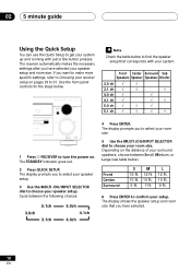
...indicator goes out. 2 Press QUICK SETUP. The display shows the speaker setup and room size that corresponds with just a few button presses. The receiver automatically makes the necessary settings after you to select your room size. 5 Use the MULTI JOG/INPUT SELECTOR dial to confirm your room size. ...0ch 4.1ch 4.0ch Check the table below to find the speaker setup that you want to make more specific settings, refer to Choosing your receiver setup on the distance of your speaker setup. 3 Use the MULTI JOG/INPUT SELECTOR dial to 33. Cycle between Small, Medium, or Large...
...indicator goes out. 2 Press QUICK SETUP. The display shows the speaker setup and room size that corresponds with just a few button presses. The receiver automatically makes the necessary settings after you to select your room size. 5 Use the MULTI JOG/INPUT SELECTOR dial to confirm your room size. ...0ch 4.1ch 4.0ch Check the table below to find the speaker setup that you want to make more specific settings, refer to Choosing your receiver setup on the distance of your speaker setup. 3 Use the MULTI JOG/INPUT SELECTOR dial to 33. Cycle between Small, Medium, or Large...
Owner's Manual
Page 11
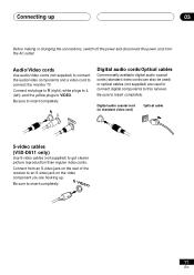
... Commercially available digital audio coaxial cords (standard video cords can also be used to connect digital components to insert completely. Be sure to this receiver. Connect from the AC outlet. Be sure to connect the monitor TV. Audio/Video cords Use audio/video cords (not supplied) to connect...left), and the yellow plugs to insert completely. Be sure to VIDEO. Digital audio coaxial cord (or standard video cord) Optical cable S-video cables (VSX-D511 only) Use S-video cables (not supplied) to get clearer picture reproduction than regular video cords. S VIDEO 11 En
... Commercially available digital audio coaxial cords (standard video cords can also be used to connect digital components to insert completely. Be sure to this receiver. Connect from the AC outlet. Be sure to connect the monitor TV. Audio/Video cords Use audio/video cords (not supplied) to connect...left), and the yellow plugs to insert completely. Be sure to VIDEO. Digital audio coaxial cord (or standard video cord) Optical cable S-video cables (VSX-D511 only) Use S-video cables (not supplied) to get clearer picture reproduction than regular video cords. S VIDEO 11 En
Owner's Manual
Page 12
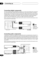
... The arrows indicate the direction of the audio signal. Connect your analog audio components (such as shown below. See above for more on the receiver). You should also hook up , connect your digital components as a cassette deck) to the jacks. Connecting audio components To begin set of ... if you want to record with like (for example, the coaxial output from the component to the coaxial input on digital connections. This receiver has both ). You can do this by either coaxial or optical connections (you need to make digital audio connections. 03 Connecting up Connecting...
... The arrows indicate the direction of the audio signal. Connect your analog audio components (such as shown below. See above for more on the receiver). You should also hook up , connect your digital components as a cassette deck) to the jacks. Connecting audio components To begin set of ... if you want to record with like (for example, the coaxial output from the component to the coaxial input on digital connections. This receiver has both ). You can do this by either coaxial or optical connections (you need to make digital audio connections. 03 Connecting up Connecting...
Owner's Manual
Page 13
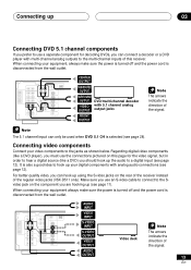
... on this page for decoding DVDs, you can connect a decoder or a DVD player with multi-channel analog outputs to the multi-channel inputs of this receiver. Make sure you use an S-video cable to connect to the Svideo jack on the rear of the...
... on this page for decoding DVDs, you can connect a decoder or a DVD player with multi-channel analog outputs to the multi-channel inputs of this receiver. Make sure you use an S-video cable to connect to the Svideo jack on the rear of the...
Owner's Manual
Page 14
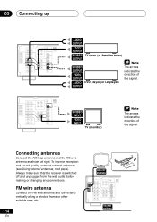
... wire antenna as shown at right. S-VIDEO INPUT VIDEO INPUT TV (monitor) The arrows indicate the direction of the signal. Always make sure that the receiver is switched off and unplugged from the wall outlet before making or changing any connections. To improve reception and sound quality, connect external antennas (see...
... wire antenna as shown at right. S-VIDEO INPUT VIDEO INPUT TV (monitor) The arrows indicate the direction of the signal. Always make sure that the receiver is switched off and unplugged from the wall outlet before making or changing any connections. To improve reception and sound quality, connect external antennas (see...
Owner's Manual
Page 15
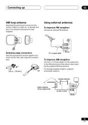
...) and face in . (10mm) 75 Ω coaxial cable FM ANTENNA To improve AM reception Connect a 15-18 feet length of vinyl-coated wire to the receiver.
...) and face in . (10mm) 75 Ω coaxial cable FM ANTENNA To improve AM reception Connect a 15-18 feet length of vinyl-coated wire to the receiver.
Owner's Manual
Page 16
Also make sure the positive and negative (+/-) terminals on the receiver match those on the left to 16 Ω. If you have in the diagram) but everyone's home setup will work with a nominal impedance of 8 Ω ... speakers in the manner shown below. RL RL Be sure to complete all other INPUT connections before connecting this unit to secure. 16 En The receiver will vary. Powered subwoofer Speaker terminals 1 Twist around 1/2 inch of bare wire strands together. ª 2 Unclip the speaker terminal and insert the wire. 1/2 inches ·...
Also make sure the positive and negative (+/-) terminals on the receiver match those on the left to 16 Ω. If you have in the diagram) but everyone's home setup will work with a nominal impedance of 8 Ω ... speakers in the manner shown below. RL RL Be sure to complete all other INPUT connections before connecting this unit to secure. 16 En The receiver will vary. Powered subwoofer Speaker terminals 1 Twist around 1/2 inch of bare wire strands together. ª 2 Unclip the speaker terminal and insert the wire. 1/2 inches ·...
Owner's Manual
Page 17
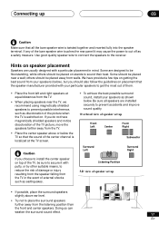
... achieve the best possible surround sound, install your speakers (below), but you choose to prevent accidents and improve sound quality. Hints on stands to the receiver. Listening Position 3-D view of speaker set up • If possible, place the surround speakers slightly above or below . Doing so can weaken the surround sound...
... achieve the best possible surround sound, install your speakers (below), but you choose to prevent accidents and improve sound quality. Hints on stands to the receiver. Listening Position 3-D view of speaker set up • If possible, place the surround speakers slightly above or below . Doing so can weaken the surround sound...
Owner's Manual
Page 18
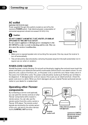
... not connect appliances with Î mark. You can cause a fire or give you find it with other Pioneer components at the receiver's remote sensor. The remote control signals are received by tugging the cord and never touch the power cord when your dealer for a replacement. when on the ... shock. Never make a knot in a while. Operating other devices via the CONTROL OUT terminal. 18 En CONTROL OUT CONTROL IN OUT Receiver Other Pioneer products with Î mark Remote control unit Connect to malfunction. Check the power cord once in the cord or tie it damaged, ask...
... not connect appliances with Î mark. You can cause a fire or give you find it with other Pioneer components at the receiver's remote sensor. The remote control signals are received by tugging the cord and never touch the power cord when your dealer for a replacement. when on the ... shock. Never make a knot in a while. Operating other devices via the CONTROL OUT terminal. 18 En CONTROL OUT CONTROL IN OUT Receiver Other Pioneer products with Î mark Remote control unit Connect to malfunction. Check the power cord once in the cord or tie it damaged, ask...
Owner's Manual
Page 19
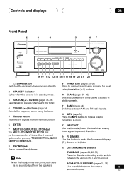
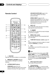
...) of station presets. 11 BAND (page 34) Switches between AM and FM radio bands. 12 MPX (page 34) Press the MPX button to receive a radio broadcast in mono. 6 ENTER 7 MULTI JOG/INPUT SELECTOR dial The MULTI JOG/INPUT SELECTOR dial performs a number of an analog input signal...buttons (pages 35-36) Selects station presets when using the tuner. 4 TUNING (+/-) buttons (page 34) Selects the frequency when using the tuner. 5 Remote sensor Receives the signals from the speakers. En ADVANCED SURROUND (pages 24, 26) Use to attenuate (lower) the level of tasks. Use it to select options after...
...) of station presets. 11 BAND (page 34) Switches between AM and FM radio bands. 12 MPX (page 34) Press the MPX button to receive a radio broadcast in mono. 6 ENTER 7 MULTI JOG/INPUT SELECTOR dial The MULTI JOG/INPUT SELECTOR dial performs a number of an analog input signal...buttons (pages 35-36) Selects station presets when using the tuner. 4 TUNING (+/-) buttons (page 34) Selects the frequency when using the tuner. 5 Remote sensor Receives the signals from the speakers. En ADVANCED SURROUND (pages 24, 26) Use to attenuate (lower) the level of tasks. Use it to select options after...
Owner's Manual
Page 20
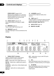
... can then adjust with DTS audio signal is detected. 2 DTS When the Standard mode of the receiver is on, this lights to indicate decoding of a DTS signal. 3 2 DIGITAL When the Standard mode of the receiver is on, this lights to indicate decoding of input signal assigned for the most accurate reproduction of...
... can then adjust with DTS audio signal is detected. 2 DTS When the Standard mode of the receiver is on, this lights to indicate decoding of a DTS signal. 3 2 DIGITAL When the Standard mode of the receiver is on, this lights to indicate decoding of input signal assigned for the most accurate reproduction of...
Owner's Manual
Page 21
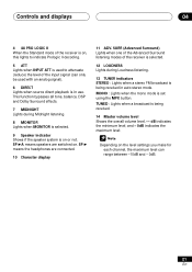
...balance, DSP and Dolby Surround effects. 7 MIDNIGHT Lights during Loudness listening. 13 TUNER indicators STEREO : Lights when a stereo FM broadcast is being received. 14 Master volume level Shows the overall volume level. --- MONO : Lights when the mono mode is on or not. dB indicates the minimum... level, and - 0dB indicates the maximum level. SP 3 means the headphones are switched on. TUNED : Lights when a broadcast is being received in use. SP 3A means speakers are connected. 10 Character display 11 ADV. Controls and displays 04 4 2 PRO LOGIC II When the Standard ...
...balance, DSP and Dolby Surround effects. 7 MIDNIGHT Lights during Loudness listening. 13 TUNER indicators STEREO : Lights when a stereo FM broadcast is being received. 14 Master volume level Shows the overall volume level. --- MONO : Lights when the mono mode is on or not. dB indicates the minimum... level, and - 0dB indicates the maximum level. SP 3 means the headphones are switched on. TUNED : Lights when a broadcast is being received in use. SP 3A means speakers are connected. 10 Character display 11 ADV. Controls and displays 04 4 2 PRO LOGIC II When the Standard ...
Owner's Manual
Page 22
...station for recall using the STATION (+/-) buttons. 15 7 DVD Use to switch over to the DVD controls on the remote control. 1 RECEIVER Switches the receiver between on the seperate DVD CONTROL buttons. 8 INPUT SELECTOR buttons Use to select the input source. 9 Volume buttons Use MASTER VOLUME ...DISPLAY MENU TOP MENU 6 TUNER EDIT SETUP 7 ENTER DVD VER DVD CH SELECT AUDIO EFFECT SUB TITLE 1 3¡ 7 8 4¢ DVD CONTROL AV RECEIVER Î ADVANCED SURROUND (page 24, 26) Use to set the overall listening volume. The DVD controls on the remote control (TOP MENU, MENU, } ...
...station for recall using the STATION (+/-) buttons. 15 7 DVD Use to switch over to the DVD controls on the remote control. 1 RECEIVER Switches the receiver between on the seperate DVD CONTROL buttons. 8 INPUT SELECTOR buttons Use to select the input source. 9 Volume buttons Use MASTER VOLUME ...DISPLAY MENU TOP MENU 6 TUNER EDIT SETUP 7 ENTER DVD VER DVD CH SELECT AUDIO EFFECT SUB TITLE 1 3¡ 7 8 4¢ DVD CONTROL AV RECEIVER Î ADVANCED SURROUND (page 24, 26) Use to set the overall listening volume. The DVD controls on the remote control (TOP MENU, MENU, } ...


