
Service Manual
Page 1
... 1, 9120 Melsele, Belgium PIONEER ELECTRONICS ASIACENTRE PTE. AUDIO/VIDEO MULTI-CHANNEL RECEIVER MULTI JOG ENTER ADVANCED ST/DIRECT SIGNAL STANDARD SURR /AUTO SURR SELECT LISTENING MODE STANDBY/ON PHONES DVD/LD TV/SAT DVR/VCR INPUT FL DIMMER ATT EXTENDED ACOUSTIC SPEAKERS MODE EQ VIDEO BAND TUNING /STATION TUNER EDIT TONE QUICK SETUP SYSTEM SETUP RETURN MULTI JOG CD CD-R/TAPE/MD TUNER AUX S-VIDEO VIDEO VIDEO INPUT L AUDIO R MCACC DIGITAL IN SETUP MIC DOWN MASTER VOLUME UP VSX-815-K AUDIO/VIDEO MULTI-CHANNEL RECEIVER VSX-815-K VSX-815-S VSX-915-K ORDER NO.
... 1, 9120 Melsele, Belgium PIONEER ELECTRONICS ASIACENTRE PTE. AUDIO/VIDEO MULTI-CHANNEL RECEIVER MULTI JOG ENTER ADVANCED ST/DIRECT SIGNAL STANDARD SURR /AUTO SURR SELECT LISTENING MODE STANDBY/ON PHONES DVD/LD TV/SAT DVR/VCR INPUT FL DIMMER ATT EXTENDED ACOUSTIC SPEAKERS MODE EQ VIDEO BAND TUNING /STATION TUNER EDIT TONE QUICK SETUP SYSTEM SETUP RETURN MULTI JOG CD CD-R/TAPE/MD TUNER AUX S-VIDEO VIDEO VIDEO INPUT L AUDIO R MCACC DIGITAL IN SETUP MIC DOWN MASTER VOLUME UP VSX-815-K AUDIO/VIDEO MULTI-CHANNEL RECEIVER VSX-815-K VSX-815-S VSX-915-K ORDER NO.

Service Manual
Page 2
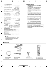
... parts in this Service Manual, may create shock, fire, or other reproductive harm. Product Safety is continuously under test Leakage current tester Reading should be of the appliance (input/output terminals, screwheads, metal overlays, control shaft, etc.). F 2 VSX-815-K 1 2 3 4 Improperly performed repairs can be obtained at a nominal charge from PIONEER. Proposition 65 NOTICE (FOR CANADIAN MODEL ONLY) Fuse symbols (fast operating fuse) and/or parts...
... parts in this Service Manual, may create shock, fire, or other reproductive harm. Product Safety is continuously under test Leakage current tester Reading should be of the appliance (input/output terminals, screwheads, metal overlays, control shaft, etc.). F 2 VSX-815-K 1 2 3 4 Improperly performed repairs can be obtained at a nominal charge from PIONEER. Proposition 65 NOTICE (FOR CANADIAN MODEL ONLY) Fuse symbols (fast operating fuse) and/or parts...

Service Manual
Page 3
... instructions described in this manual. Please replace the wiring and cables to restore their original state. If you find a damaged power cord, please exchange it is required due to your surroundings and repair safely. 2. Lubricants, Glues, and Replacement parts Use grease and adhesives that there are no cold solder and other debris. F VSX-815-K 3 5 6 7 8 Please follow the specified safety methods when modification(addition/change...
... instructions described in this manual. Please replace the wiring and cables to restore their original state. If you find a damaged power cord, please exchange it is required due to your surroundings and repair safely. 2. Lubricants, Glues, and Replacement parts Use grease and adhesives that there are no cold solder and other debris. F VSX-815-K 3 5 6 7 8 Please follow the specified safety methods when modification(addition/change...

Service Manual
Page 4
... 7.3.2 IC DATA TRANSMISSION TIMING CHART 73 7.3.3 DETECTION CIRCUIT ...76 7.3.4 AMPLIFIER SYSTEM PROTECTION OPERATION SPECIFICATION 77 7.3.5 AMPLIFIER FAILURE DIAGNOSIS FLOW CHART 79 7.4 CLEANING...79 8. SW & KEY, H. ENCODER, P. ENCODER, P. SW&FUNC KEY and F. INPUT, COMPONENT and PRE-OUT ASSYS 54 5. IN, COMPONENT and F.OPT & MIC ASSYS 34 3.13 VIDEO CONVERTER ASSY ...36 4. ADJUSTMENT ...62 7. P. ELECTRICAL PARTS LIST ...56 6. SPECIFICATIONS ...5 A 2. BLOCK DIAGRAM AND SCHEMATIC DIAGRAM 12 3.1 BLOCK DIAGRAM ...12 3.2 OVERALL WIRING CONNECTION DIAGRAM 14 3.3 MAIN...
... 7.3.2 IC DATA TRANSMISSION TIMING CHART 73 7.3.3 DETECTION CIRCUIT ...76 7.3.4 AMPLIFIER SYSTEM PROTECTION OPERATION SPECIFICATION 77 7.3.5 AMPLIFIER FAILURE DIAGNOSIS FLOW CHART 79 7.4 CLEANING...79 8. SW & KEY, H. ENCODER, P. ENCODER, P. SW&FUNC KEY and F. INPUT, COMPONENT and PRE-OUT ASSYS 54 5. IN, COMPONENT and F.OPT & MIC ASSYS 34 3.13 VIDEO CONVERTER ASSY ...36 4. ADJUSTMENT ...62 7. P. ELECTRICAL PARTS LIST ...56 6. SPECIFICATIONS ...5 A 2. BLOCK DIAGRAM AND SCHEMATIC DIAGRAM 12 3.1 BLOCK DIAGRAM ...12 3.2 OVERALL WIRING CONNECTION DIAGRAM 14 3.3 MAIN...

Service Manual
Page 5
...;) Surround Back 110 W per channel (1kHz, 1.0%, 8 Ω) Audio section • Input (Sensitivity/Impedance) CD, DVR/VCR, CD-R/TAPE/MD, DVD/LD, TV/SAT 200 mV/47 kΩ • Frequency response CD, DVR/VCR, CD-R/TAPE/MD, DVD/LD, TV/SAT . . . . . . . . . . . . . .5 Hz to 100,000 Hz +0 - 3 dB • Output (Level/Impedance) DVR/VCR REC, CD-R/TAPE/ MD REC 200 mV/2.2 kΩ • Tone control Bass 6 dB (100 Hz) Treble...
...;) Surround Back 110 W per channel (1kHz, 1.0%, 8 Ω) Audio section • Input (Sensitivity/Impedance) CD, DVR/VCR, CD-R/TAPE/MD, DVD/LD, TV/SAT 200 mV/47 kΩ • Frequency response CD, DVR/VCR, CD-R/TAPE/MD, DVD/LD, TV/SAT . . . . . . . . . . . . . .5 Hz to 100,000 Hz +0 - 3 dB • Output (Level/Impedance) DVR/VCR REC, CD-R/TAPE/ MD REC 200 mV/2.2 kΩ • Tone control Bass 6 dB (100 Hz) Treble...
Service Manual
Page 6
...-R/TAPE TUNER RECEIVER FL DIMMER +10 D.ACCESS TOP MENU TUNE SR DISC ENTER CLASS MENU DTV MENU ST T.EDIT ENTER ST BAND SYSTEM TUNE GUIDE SETUP TV CONTROL RETURN TVVOL INPUT SELECT TV CH VOL DTVON/OFF REC DTVINFO MUTE TUNER DISPLAY RECSTOP MPX AUDIO CHRETURN SUBTITLE HDD DVD CH CH RECEIVERCONTROL STANDARD ADV.SURR STEREO SLEEP MIDNIGHT/ ACOUSTIC LOUDNESS DIALOGE EQ INPUTATT SHIFT EFFECT /CH SEL LEVEL RECEIVER Remote control unit (VSX-915 : XXD3083) (VSX...
...-R/TAPE TUNER RECEIVER FL DIMMER +10 D.ACCESS TOP MENU TUNE SR DISC ENTER CLASS MENU DTV MENU ST T.EDIT ENTER ST BAND SYSTEM TUNE GUIDE SETUP TV CONTROL RETURN TVVOL INPUT SELECT TV CH VOL DTVON/OFF REC DTVINFO MUTE TUNER DISPLAY RECSTOP MPX AUDIO CHRETURN SUBTITLE HDD DVD CH CH RECEIVERCONTROL STANDARD ADV.SURR STEREO SLEEP MIDNIGHT/ ACOUSTIC LOUDNESS DIALOGE EQ INPUTATT SHIFT EFFECT /CH SEL LEVEL RECEIVER Remote control unit (VSX-915 : XXD3083) (VSX...
Service Manual
Page 7
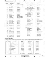
... XHA3149 (2) CONTRAST TABLE VSX-815-K/KUXJ/CA, VSX-815-S/KUXJ/CA and VSX-915-K/KUXJ/CA are used for the following: Mark NO Description VSX-815-K /KUXJ/CA VSX-815-S /KUXJ/CA VSX-915-K /KUXJ/CA 6 Remote Control Unit XXD3086 XXD3086 XXD3083 12 Packing Case XHD3472 XHD3473 XHD3471 F VSX-815-K 7 5 6 7 8 Therefore, when replacing, be sure to mark on some component parts indicates the importance of...
... XHA3149 (2) CONTRAST TABLE VSX-815-K/KUXJ/CA, VSX-815-S/KUXJ/CA and VSX-915-K/KUXJ/CA are used for the following: Mark NO Description VSX-815-K /KUXJ/CA VSX-815-S /KUXJ/CA VSX-915-K /KUXJ/CA 6 Remote Control Unit XXD3086 XXD3086 XXD3083 12 Packing Case XHD3472 XHD3473 XHD3471 F VSX-815-K 7 5 6 7 8 Therefore, when replacing, be sure to mark on some component parts indicates the importance of...
Service Manual
Page 9
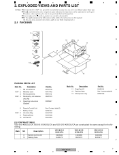
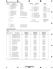
Description 1 MAIN Assy 2 DSP Assy 3 VIDEO CONVERTER Assy 4 AMP & PRIMARY Assy 5 TRANS1 Assy 6 Part No. VIDEO Assy 15 PRE-OUT Assy XWZ3907 XWZ3915 See Contrast table(2) See Contrast table(2) XWZ3938 16 DIGITAL INPUT Assy 17 COMPONENT Assy 18 FM/AM TUNER UNIT > 19 FU1 Fuse (10A) > 20 FU701 Fuse (10A) XWZ3999 XWZ3935 AXX7172 REK1087 REK1087 > 21 Transformer 915KU > 22 AC Power Cord 23 Cord Stopper 24...
Description 1 MAIN Assy 2 DSP Assy 3 VIDEO CONVERTER Assy 4 AMP & PRIMARY Assy 5 TRANS1 Assy 6 Part No. VIDEO Assy 15 PRE-OUT Assy XWZ3907 XWZ3915 See Contrast table(2) See Contrast table(2) XWZ3938 16 DIGITAL INPUT Assy 17 COMPONENT Assy 18 FM/AM TUNER UNIT > 19 FU1 Fuse (10A) > 20 FU701 Fuse (10A) XWZ3999 XWZ3935 AXX7172 REK1087 REK1087 > 21 Transformer 915KU > 22 AC Power Cord 23 Cord Stopper 24...
Service Manual
Page 11
... 16 17 TUNER BTN 18 Sub BTN 19 JOG BUTTON See Contrast table(2) See Contrast table(2) See Contrast table(2) (2) CONTRAST TABLE C VSX-815-K/KUXJ/CA, VSX-815-S/KUXJ/CA and VSX-915-K/KUXJ/CA are constructed the same except for the fol- 5 6 FRONT PANEL SECTION parts List Mark No. Assy Part No. XWZ3911 XWZ3922 XWZ3919 XWZ3965 XWZ3924 6 FRONT INPUT Assy 7 Standby BTN...
... 16 17 TUNER BTN 18 Sub BTN 19 JOG BUTTON See Contrast table(2) See Contrast table(2) See Contrast table(2) (2) CONTRAST TABLE C VSX-815-K/KUXJ/CA, VSX-815-S/KUXJ/CA and VSX-915-K/KUXJ/CA are constructed the same except for the fol- 5 6 FRONT PANEL SECTION parts List Mark No. Assy Part No. XWZ3911 XWZ3922 XWZ3919 XWZ3965 XWZ3924 6 FRONT INPUT Assy 7 Standby BTN...
Service Manual
Page 15
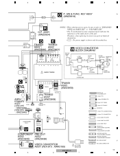
... FU1 CN551 XDD3168 (tape 20mm) J46 8/140 COMPONENT VIDEO U CN1575 PREOUT S CN51 COMPONENT PRE-OUT ASSY ASSY (XWZ3935) (XWZ3938) CN1101 VIDEO CONVERTOR W VIDEO CONVERTOR ASSY (VSX-915 : XWK3185) VSX-815-K 5 6 AC CORD ADG7024 7 D B*B-PH-K-S PH CONNECTOR 1.25mm FFC 1.25mm REVERSE FFC 2.0mm FLAT CABLE 1.5mm FLAT CABLE BOARD IN 1.25mm FFC CONNECTOR(L) 1.25mm FFC CONNECTOR E 2.0mm CABLE HOLDER 1.5mm CABLE HOLDER 2.0mm WIRE TRAP KP200TA**L 2.0mm...
... FU1 CN551 XDD3168 (tape 20mm) J46 8/140 COMPONENT VIDEO U CN1575 PREOUT S CN51 COMPONENT PRE-OUT ASSY ASSY (XWZ3935) (XWZ3938) CN1101 VIDEO CONVERTOR W VIDEO CONVERTOR ASSY (VSX-915 : XWK3185) VSX-815-K 5 6 AC CORD ADG7024 7 D B*B-PH-K-S PH CONNECTOR 1.25mm FFC 1.25mm REVERSE FFC 2.0mm FLAT CABLE 1.5mm FLAT CABLE BOARD IN 1.25mm FFC CONNECTOR(L) 1.25mm FFC CONNECTOR E 2.0mm CABLE HOLDER 1.5mm CABLE HOLDER 2.0mm WIRE TRAP KP200TA**L 2.0mm...
Service Manual
Page 33
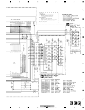
... SETUP S467 1.8 TONE S468 2.4 TUNER EDIT S469 3.0 TUNING/ STATION S470 *1 3.6 4.2 KEY IN VOLTAGE [V] J41 D15A03-110-2651 R504 1.2k S503 1.2 ADVANCED SURROUND S504 1.8 STEREO/ DIRECT S505 2.4 SIGNAL SELECT C R505 1.6k *3 D501 R501 VSX-915, VSX-815 SLR-343BBT (FGHJ) 390 D G11 R550 180 P FRONT KEY ASSY (XWZ3965) C410 0.01 YB C415 1000p YB *1 S451 S452 VSX-915, 815 /KUXJ/CA AUX TUNER FRONT KEY ASSY S451 : AUX S452 : TUNER...
... SETUP S467 1.8 TONE S468 2.4 TUNER EDIT S469 3.0 TUNING/ STATION S470 *1 3.6 4.2 KEY IN VOLTAGE [V] J41 D15A03-110-2651 R504 1.2k S503 1.2 ADVANCED SURROUND S504 1.8 STEREO/ DIRECT S505 2.4 SIGNAL SELECT C R505 1.6k *3 D501 R501 VSX-915, VSX-815 SLR-343BBT (FGHJ) 390 D G11 R550 180 P FRONT KEY ASSY (XWZ3965) C410 0.01 YB C415 1000p YB *1 S451 S452 VSX-915, 815 /KUXJ/CA AUX TUNER FRONT KEY ASSY S451 : AUX S452 : TUNER...

Service Manual
Page 48
... MODE) INPUT ATT (PTY SEARCH) S461 S462 S463 SPEAKER (SPK IMPEDANCE) EXTENDED MODE ACOUSTIC EQ 11 J40 1 W288 14 10 14 550 R HCI40HI S470 BAND (CLASS) S469 TUNING/STATION S468 TUNER EDIT S467 TONE S466 QUICK SETUP S465 SYSTEM SETUP S464 RETURN XWZ3913 XWZ3965 D O POWER SW & KEY ASSY 1 KEY1 2 PWRON LED 3 GNDU PWR & KEY S502 S503 STANDARD ADV.SUR S504 S505 SIGNAL SELECT 11 3 3 STEREO/ DIRECT...
... MODE) INPUT ATT (PTY SEARCH) S461 S462 S463 SPEAKER (SPK IMPEDANCE) EXTENDED MODE ACOUSTIC EQ 11 J40 1 W288 14 10 14 550 R HCI40HI S470 BAND (CLASS) S469 TUNING/STATION S468 TUNER EDIT S467 TONE S466 QUICK SETUP S465 SYSTEM SETUP S464 RETURN XWZ3913 XWZ3965 D O POWER SW & KEY ASSY 1 KEY1 2 PWRON LED 3 GNDU PWR & KEY S502 S503 STANDARD ADV.SUR S504 S505 SIGNAL SELECT 11 3 3 STEREO/ DIRECT...

Service Manual
Page 77
... power-on the display. ↓ The abnormality continues for 3 seconds. ↓ Continues. If the "L" is turned off .) 2. When an overload is detected, A.MUTE* is turned on, speaker relay is detected, the microprocessor will perform as following flow chart. The program restarts. ↓ Power key not effective and POWER LED blinks. B ↓ Recovery The power is input, the DC_DET port becomes "L". 5 6 7 8 7.3.4 AMPLIFIER SYSTEM PROTECTION OPERATION SPECIFICATION...
... power-on the display. ↓ The abnormality continues for 3 seconds. ↓ Continues. If the "L" is turned off .) 2. When an overload is detected, A.MUTE* is turned on, speaker relay is detected, the microprocessor will perform as following flow chart. The program restarts. ↓ Power key not effective and POWER LED blinks. B ↓ Recovery The power is input, the DC_DET port becomes "L". 5 6 7 8 7.3.4 AMPLIFIER SYSTEM PROTECTION OPERATION SPECIFICATION...

Service Manual
Page 80
.../MD TUNER AUX LISTENING MODE B STANDBY/ON INPUT FL DIMMER ATT EXTENDED ACOUSTIC SPEAKERS MODE EQ S-VIDEO VIDEO VIDEO INPUT L AUDIO R MCACC DIGITAL IN SETUP MIC PHONES BAND TUNING /STATION TUNER EDIT TONE QUICK SETUP SYSTEM SETUP RETURN MULTI JOG DOWN MASTER VOLUME UP 6 7 8 9 C ADVANCED ST/DIRECT SIGNAL STANDARD SURR /AUTO SURR SELECT LISTENING MODE D 1 Input select buttons Press to select an input source. 2 Character display See Display. 3 MCACC indicator Lights when Acoustic Calibration EQ is on (Acoustic Calibration EQ is automatically set to ALL CH ADJUST...
.../MD TUNER AUX LISTENING MODE B STANDBY/ON INPUT FL DIMMER ATT EXTENDED ACOUSTIC SPEAKERS MODE EQ S-VIDEO VIDEO VIDEO INPUT L AUDIO R MCACC DIGITAL IN SETUP MIC PHONES BAND TUNING /STATION TUNER EDIT TONE QUICK SETUP SYSTEM SETUP RETURN MULTI JOG DOWN MASTER VOLUME UP 6 7 8 9 C ADVANCED ST/DIRECT SIGNAL STANDARD SURR /AUTO SURR SELECT LISTENING MODE D 1 Input select buttons Press to select an input source. 2 Character display See Display. 3 MCACC indicator Lights when Acoustic Calibration EQ is on (Acoustic Calibration EQ is automatically set to ALL CH ADJUST...

Service Manual
Page 81
.... 22 QUICK SETUP See Using the Quick Setup. 23 System Setup menu controls SYSTEM SETUP C Use with the MULTI JOG dial to confirm and exit the current menu. STEREO/DIRECT (AUTO SURR) Switches between the tuner AM and FM bands. 19 TUNING / STATION buttons Selects the frequency and station presets when using the tuner. D Rear panel VSX-815-K,S only VSX-915-K only CEN- SUB TER WOOFER IN AUX MONITOR OUT FM UNBAL AM COMPONENT VIDEO S-VIDEO IN CD 75 Ω LOOP ANTENNA R (DVR/ VCR) IN π ASSIGNABLE (DVD/ LD...
.... 22 QUICK SETUP See Using the Quick Setup. 23 System Setup menu controls SYSTEM SETUP C Use with the MULTI JOG dial to confirm and exit the current menu. STEREO/DIRECT (AUTO SURR) Switches between the tuner AM and FM bands. 19 TUNING / STATION buttons Selects the frequency and station presets when using the tuner. D Rear panel VSX-815-K,S only VSX-915-K only CEN- SUB TER WOOFER IN AUX MONITOR OUT FM UNBAL AM COMPONENT VIDEO S-VIDEO IN CD 75 Ω LOOP ANTENNA R (DVR/ VCR) IN π ASSIGNABLE (DVD/ LD...

Service Manual
Page 82
... lights to indicate Pro Logic IIx decoding (see Auto playback). Lights when Dialog Enhancement (DIALOG E) is switched on , this . 82 VSX-815-K 1 2 3 4 See Checking your Acoustic Calibration EQ settings. Lights when a broadcast is being received in auto stereo mode. Lights when the Auto Surround feature is in surround sound). 5 VIR.SB Lights during Midnight listening. 17 D.E. Direct playback bypasses the tone controls and channel levels for more on . DIGITAL Lights when a digital audio signal is detected. 2 DIGITAL Lights when a Dolby Digital encoded signal...
... lights to indicate Pro Logic IIx decoding (see Auto playback). Lights when Dialog Enhancement (DIALOG E) is switched on , this . 82 VSX-815-K 1 2 3 4 See Checking your Acoustic Calibration EQ settings. Lights when a broadcast is being received in auto stereo mode. Lights when the Auto Surround feature is in surround sound). 5 VIR.SB Lights during Midnight listening. 17 D.E. Direct playback bypasses the tone controls and channel levels for more on . DIGITAL Lights when a digital audio signal is detected. 2 DIGITAL Lights when a Dolby Digital encoded signal...

Service Manual
Page 83
...; menu of your system). 4 Number buttons and other receiver/ B component controls Use the number buttons to directly select a radio frequency or the tracks on a CD, DVD, etc. GUIDE Displays the guides on a digital TV. T. E F VSX-815-K 83 5 6 7 8 5 6 Remote control RECEIVER INPUT SELECT 1 2 SOURCE 11 12 DVD/LD TV/SAT DVR/VCR TV CONT 3 MULTI CONTROL CD CD-R/TAPE TUNER RECEIVER 13 4 FL DIMMER +10 SR DISC ENTER D.ACCESS TOP MENU 5 TUNE CLASS MENU DTV MENU ST ST 6 T.EDIT ENTER BAND SYSTEM TUNE GUIDE SETUP TV CONTROL RETURN 7 TV VOL INPUT SELECT TV...
...; menu of your system). 4 Number buttons and other receiver/ B component controls Use the number buttons to directly select a radio frequency or the tracks on a CD, DVD, etc. GUIDE Displays the guides on a digital TV. T. E F VSX-815-K 83 5 6 7 8 5 6 Remote control RECEIVER INPUT SELECT 1 2 SOURCE 11 12 DVD/LD TV/SAT DVR/VCR TV CONT 3 MULTI CONTROL CD CD-R/TAPE TUNER RECEIVER 13 4 FL DIMMER +10 SR DISC ENTER D.ACCESS TOP MENU 5 TUNE CLASS MENU DTV MENU ST ST 6 T.EDIT ENTER BAND SYSTEM TUNE GUIDE SETUP TV CONTROL RETURN 7 TV VOL INPUT SELECT TV...

Service Manual
Page 84
... 8 Component control buttons The main buttons ( , , etc.) are dedicated to control the TV assigned to hook up information screens on /off the power of a double cassette deck player. DTV ON/OFF Switches a digital TV on a digital TV. AUDIO Changes the audio language or channel on /off . F 84 VSX-815-K 1 2 3 4 Use C the TUNE +/- buttons to find preset stations. 7 TV CONTROL buttons These buttons are used to turn on DVD discs. INPUT SELECT Use to mono will improve the sound quality. MENU Displays the disc menu of FM broadcasts. TV Use to control DVD...
... 8 Component control buttons The main buttons ( , , etc.) are dedicated to control the TV assigned to hook up information screens on /off the power of a double cassette deck player. DTV ON/OFF Switches a digital TV on a digital TV. AUDIO Changes the audio language or channel on /off . F 84 VSX-815-K 1 2 3 4 Use C the TUNE +/- buttons to find preset stations. 7 TV CONTROL buttons These buttons are used to turn on DVD discs. INPUT SELECT Use to mono will improve the sound quality. MENU Displays the disc menu of FM broadcasts. TV Use to control DVD...

Service Manual
Page 85
...re setting the remote to set up surround sound. 14 VOL +/- ADV. INPUT ATT Attenuates (lowers) the level of an analog input signal to the receiver. 5 6 7 8 12 Character display (LCD) This display shows information when transmitting control signals. RESET See Erasing all of the remote control button settings. Also use the LEVEL +/- 5 6 9 RECEIVER CONTROL buttons STANDARD Press for the most accurate reproduction of a source. Direct playback bypasses the tone controls and any other components connected to prevent distortion. Also selects the Auto Surround mode...
...re setting the remote to set up surround sound. 14 VOL +/- ADV. INPUT ATT Attenuates (lowers) the level of an analog input signal to the receiver. 5 6 7 8 12 Character display (LCD) This display shows information when transmitting control signals. RESET See Erasing all of the remote control button settings. Also use the LEVEL +/- 5 6 9 RECEIVER CONTROL buttons STANDARD Press for the most accurate reproduction of a source. Direct playback bypasses the tone controls and any other components connected to prevent distortion. Also selects the Auto Surround mode...

Service Manual
Page 86
... TUNING /STA TION TUNER EDIT TONE Q UICK SETUP SYSTEM SETUP RETURN MUL TI J O G CD CD-R/TAPE/MD TUNER AUX S-VIDEO VIDEO VIDEO INPUT L AUDIO R MCACC DIGITAL IN SETUP MIC DOWN This receiver MASTER VOL UME UP To make the most of the SR+ features, you should connect your source components (DVD player, etc.) in a slightly different way to that they are switched on setting up the receiver. F 3 4 For each component, connect the video output directly to the plasma display, and just connect the audio (analog...
... TUNING /STA TION TUNER EDIT TONE Q UICK SETUP SYSTEM SETUP RETURN MUL TI J O G CD CD-R/TAPE/MD TUNER AUX S-VIDEO VIDEO VIDEO INPUT L AUDIO R MCACC DIGITAL IN SETUP MIC DOWN This receiver MASTER VOL UME UP To make the most of the SR+ features, you should connect your source components (DVD player, etc.) in a slightly different way to that they are switched on setting up the receiver. F 3 4 For each component, connect the video output directly to the plasma display, and just connect the audio (analog...


