
Owner's Manual
Page 1
...-CHANNEL RECEIVER VSX-1016TXV-K Register your product at www.pioneerelectronics.com (US) www.pioneerelectronics.ca (Canada) • Protect your new investment The details of your purchase will be on file for reference in the event of an insurance claim such as loss or theft. • Receive free ...tips, updates and service bulletins on your new product • Improve product development Your input helps us continue to design products that meet your needs. • Receive a free Pioneer newsletter Registered customers can opt in to...
...-CHANNEL RECEIVER VSX-1016TXV-K Register your product at www.pioneerelectronics.com (US) www.pioneerelectronics.ca (Canada) • Protect your new investment The details of your purchase will be on file for reference in the event of an insurance claim such as loss or theft. • Receive free ...tips, updates and service bulletins on your new product • Improve product development Your input helps us continue to design products that meet your needs. • Receive a free Pioneer newsletter Registered customers can opt in to...
Owner's Manual
Page 2
... Rules. Operation is no guarantee that may not cause harmful interference, and (2) this device must accept any interference received, including interference that interference will expose you to chemicals listed on proposition 65 known to provide reasonable protection against harmful... radio/TV technician for connections. and Australia Model C67-7-3_En Product Name: AUDIO/VIDEO MULTI-CHANNEL RECEIVER Model Number: VSX-1016TXV-K Responsible Party Name: PIONEER ELECTRONICS SERVICE INC. If this product or cords associated with accessories sold with Canadian ICES-003. Wash...
... Rules. Operation is no guarantee that may not cause harmful interference, and (2) this device must accept any interference received, including interference that interference will expose you to chemicals listed on proposition 65 known to provide reasonable protection against harmful... radio/TV technician for connections. and Australia Model C67-7-3_En Product Name: AUDIO/VIDEO MULTI-CHANNEL RECEIVER Model Number: VSX-1016TXV-K Responsible Party Name: PIONEER ELECTRONICS SERVICE INC. If this product or cords associated with accessories sold with Canadian ICES-003. Wash...
Owner's Manual
Page 4
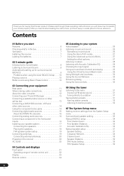
...32 Listening to your model properly. Please read through these operating instructions so you start Features 6 Checking what's in the box 6 Ventilation 7 Installing the receiver 7 Loading the batteries 7 02 5 minute guide Introduction to home theater 8 Listening to Surround Sound 8 Automatically setting up for surround sound (MCACC 8 Problems...38 Channel Level 38 Speaker Distance 39 THX Audio Setting 39 THX Speaker Setup 39 4 En After you for buying this Pioneer product. Thank you have finished reading the instructions, put them away in a safe place for future reference.
...32 Listening to your model properly. Please read through these operating instructions so you start Features 6 Checking what's in the box 6 Ventilation 7 Installing the receiver 7 Loading the batteries 7 02 5 minute guide Introduction to home theater 8 Listening to Surround Sound 8 Automatically setting up for surround sound (MCACC 8 Problems...38 Channel Level 38 Speaker Distance 39 THX Audio Setting 39 THX Speaker Setup 39 4 En After you for buying this Pioneer product. Thank you have finished reading the instructions, put them away in a safe place for future reference.
Owner's Manual
Page 5
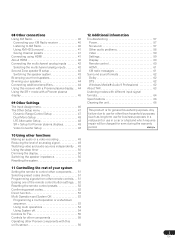
... Bi-amping your front speakers 43 Bi-wiring your speakers 44 Connecting additional amplifiers 44 Using this receiver with a Pioneer plasma display. . . 44 Using the SR+ mode with a Pioneer plasma display 45 09 Other Settings The Input Assign menu 46 The Other Setup menu 47 Dynamic ...preset codes directly 51 Programming signals from other remote controls. . . 51 Erasing one of your system Setting the remote to use for other Pioneer components with this unit's sensor 56 12 Additional information Troubleshooting 57 Power 57 No sound 57 Other audio problems 58 Video 59 Settings 59 ...
... Bi-amping your front speakers 43 Bi-wiring your speakers 44 Connecting additional amplifiers 44 Using this receiver with a Pioneer plasma display. . . 44 Using the SR+ mode with a Pioneer plasma display 45 09 Other Settings The Input Assign menu 46 The Other Setup menu 47 Dynamic ...preset codes directly 51 Programming signals from other remote controls. . . 51 Erasing one of your system Setting the remote to use for other Pioneer components with this unit's sensor 56 12 Additional information Troubleshooting 57 Power 57 No sound 57 Other audio problems 58 Video 59 Settings 59 ...
Owner's Manual
Page 6
... Setting up for home theater sound is compatible with the addition of a surround back speaker, you can program the remote to Pioneer for any stereo source. This includes testing of pre-amplifier and power amplifier performance and operation, and hundreds of other parameters in ...both the digital and analog domain, making your TV. Through symmetrical placement of power amplification units, this receiver, but will also generate convincing surround sound for high-power drivability, low distortion and stable imaging. Using a system of preset codes,...
... Setting up for home theater sound is compatible with the addition of a surround back speaker, you can program the remote to Pioneer for any stereo source. This includes testing of pre-amplifier and power amplifier performance and operation, and hundreds of other parameters in ...both the digital and analog domain, making your TV. Through symmetrical placement of power amplification units, this receiver, but will also generate convincing surround sound for high-power drivability, low distortion and stable imaging. Using a system of preset codes,...

Owner's Manual
Page 7
Observe the following places: - Installing the receiver • When installing this unit, make sure to leave space around the unit for ventilation and to protect the equipment from overheating. in places that ... that have different voltages. It can cause batteries to leak, overheat, explode or catch fire. in the cabinet are very dusty - Loading the batteries 8 inches Receiver (20 cm) Slot and openings in places that gives off a magnetic field). Do not use different batteries together. • When disposing of the batteries properly...
Observe the following places: - Installing the receiver • When installing this unit, make sure to leave space around the unit for ventilation and to protect the equipment from overheating. in places that ... that have different voltages. It can cause batteries to leak, overheat, explode or catch fire. in the cabinet are very dusty - Loading the batteries 8 inches Receiver (20 cm) Slot and openings in places that gives off a magnetic field). Do not use different batteries together. • When disposing of the batteries properly...

Owner's Manual
Page 8
... Back Left (SBL) Caution • The test tones used in the Auto MCACC Setup are several other possibilities (like you're in the receiver and switch it on, followed by your DVD player, your listening area, taking into account ambient noise, speaker size and distance, and tests ... decode multichannel Dolby Digital, DTS, or Dolby Surround sources according to your speaker setup, but other sound options you can simply leave the receiver in Installing your speaker system on page 17. Important • Make sure the microphone and speakers are explained in mind, so with your...
... Back Left (SBL) Caution • The test tones used in the Auto MCACC Setup are several other possibilities (like you're in the receiver and switch it on, followed by your DVD player, your listening area, taking into account ambient noise, speaker size and distance, and tests ... decode multichannel Dolby Digital, DTS, or Dolby Surround sources according to your speaker setup, but other sound options you can simply leave the receiver in Installing your speaker system on page 17. Important • Make sure the microphone and speakers are explained in mind, so with your...
Owner's Manual
Page 9
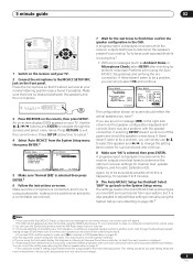
... SYSTEM SETUP RETURN TONE TUNING/ STATION TUNER EDIT SPEAKERS MULTI JOG S -VIDEO VIDEO/GAME INPUT VIDEO L AUDIO R DIGITAL IN MCACC SETUP MIC 3 Press RECEIVER on -screen. Use the / / / buttons and ENTER to navigate through Surround back speaker setting on page 33 and make sure YES is selected in bold...DTVMENU ST SETUP ENTER MENU ST T.EDIT RETURN TUNE GUIDE CATEGORY TV CONTROL BAND TV VOL INPUT SELECT TV CH VOL 1 Switch on the receiver and your room, sometimes identical speakers with cone sizes of your TV. 2 Connect the microphone to the MCACC SETUP MIC jack on the front...
... SYSTEM SETUP RETURN TONE TUNING/ STATION TUNER EDIT SPEAKERS MULTI JOG S -VIDEO VIDEO/GAME INPUT VIDEO L AUDIO R DIGITAL IN MCACC SETUP MIC 3 Press RECEIVER on -screen. Use the / / / buttons and ENTER to navigate through Surround back speaker setting on page 33 and make sure YES is selected in bold...DTVMENU ST SETUP ENTER MENU ST T.EDIT RETURN TUNE GUIDE CATEGORY TV CONTROL BAND TV VOL INPUT SELECT TV CH VOL 1 Switch on the receiver and your room, sometimes identical speakers with cone sizes of your TV. 2 Connect the microphone to the MCACC SETUP MIC jack on the front...

Owner's Manual
Page 10
...listening position. Start by switching on the playback component (for example a DVD player), your TV1 and subwoofer (if you have one), then the receiver (press RECEIVER). • Make sure the setup mic is disconnected. 2 Select the input source you want to PCM. • Depending on your TV .... If two waveforms are playing a stereo source, you will be incorrect. 02 5 minute guide Problems when using Basic Phase Control This receiver's Basic Phase Control feature uses phase correction measures to make sure that the VIDEO 1 input is on and we recommend leaving Phase Control ...
...listening position. Start by switching on the playback component (for example a DVD player), your TV1 and subwoofer (if you have one), then the receiver (press RECEIVER). • Make sure the setup mic is disconnected. 2 Select the input source you want to PCM. • Depending on your TV .... If two waveforms are playing a stereo source, you will be incorrect. 02 5 minute guide Problems when using Basic Phase Control This receiver's Basic Phase Control feature uses phase correction measures to make sure that the VIDEO 1 input is on and we recommend leaving Phase Control ...
Owner's Manual
Page 11
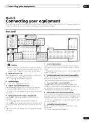
...S-video and stereo analog audio. Connecting digital audio sources on page 46 to assign the inputs. 5 Control input/output Use to connect other Pioneer components with many connection possibilities, but it doesn't have to be the final step. 1 HDMI connectors (x3) Two inputs and one output ...(x6) Use for connection to audio sources such as DVD players/recorders, VCRs, etc. Connecting your equipment 03 Chapter 3 Connecting your equipment This receiver provides you with this unit's sensor on page 16. 7 Component video connections (x4) Use the inputs to connect any video source that you...
...S-video and stereo analog audio. Connecting digital audio sources on page 46 to assign the inputs. 5 Control input/output Use to connect other Pioneer components with many connection possibilities, but it doesn't have to be the final step. 1 HDMI connectors (x3) Two inputs and one output ...(x6) Use for connection to audio sources such as DVD players/recorders, VCRs, etc. Connecting your equipment 03 Chapter 3 Connecting your equipment This receiver provides you with this unit's sensor on page 16. 7 Component video connections (x4) Use the inputs to connect any video source that you...
Owner's Manual
Page 12
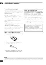
... in Video Converter Setup on page 48) OFF. About the video converter When the video converter is protected by Macrovision. Use of the receiver. • When connecting optical cables, be damaged if bent around sharp corners. Reverse engineering or disassembly is intended for front, center, surround... See Video Converter Setup on page 48 to switch the video converter on page 17 for connection to a DVD player with the receiver. 03 Connecting your equipment 10 Multichannel pre-amplifier outputs Use to connect separate amplifiers for home and other intellectual property rights. Note ...
... in Video Converter Setup on page 48) OFF. About the video converter When the video converter is protected by Macrovision. Use of the receiver. • When connecting optical cables, be damaged if bent around sharp corners. Reverse engineering or disassembly is intended for front, center, surround... See Video Converter Setup on page 48 to switch the video converter on page 17 for connection to a DVD player with the receiver. 03 Connecting your equipment 10 Multichannel pre-amplifier outputs Use to connect separate amplifiers for home and other intellectual property rights. Note ...
Owner's Manual
Page 13
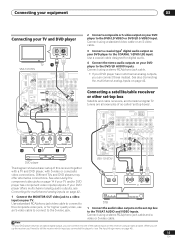
... cable. Note 1 If your DVD player has multichannel analog outputs, you connected the player to (see Connecting the multichannel analog inputs on page 42. TV 1 VSX-1016TXV OPTICAL IN 1 DIGITAL OUT ANTENNA IN 1 IN 2 (DVR/ VCR1) IN 2 (TV/SAT) OUT HDMI IN 3 (CD) ASSIGNABLE 13 CONTROL OUT XM...IN CD-R/TAPE/MD DVD/LD TV/SAT DVR/VCR1 VSX-1016TXV AM LOOP L OUT P CENTER L IN 3 R SUB R FRONT WOOFER OUT IN MONITOR OUT OUT IN L DVR/VCR2 R FRONT MULTI C The diagram shows a basic setup of the optical inputs on this receiver together with a TV and DVD player, with S-video...
... cable. Note 1 If your DVD player has multichannel analog outputs, you connected the player to (see Connecting the multichannel analog inputs on page 42. TV 1 VSX-1016TXV OPTICAL IN 1 DIGITAL OUT ANTENNA IN 1 IN 2 (DVR/ VCR1) IN 2 (TV/SAT) OUT HDMI IN 3 (CD) ASSIGNABLE 13 CONTROL OUT XM...IN CD-R/TAPE/MD DVD/LD TV/SAT DVR/VCR1 VSX-1016TXV AM LOOP L OUT P CENTER L IN 3 R SUB R FRONT WOOFER OUT IN MONITOR OUT OUT IN L DVR/VCR2 R FRONT MULTI C The diagram shows a basic setup of the optical inputs on this receiver together with a TV and DVD player, with S-video...
Owner's Manual
Page 14
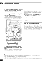
... this receiver using a coaxial digital audio cable. Using the component video jacks Component video should give superior picture quality when compared to the recorder's audio/ video inputs. You can also take advantage of the video player/recorder to the DVR/VCR1 AUDIO and VIDEO inputs. VSX-1016TXV OPTICAL ...check whether they are both compatible), which input you can output digital audio, connect an optical-type3 digital audio output from your set up the receiver you set -top box to the OPTICAL 2 (TV/SAT) input.2 Use an optical cable for the connection.4 • For a second ...
... this receiver using a coaxial digital audio cable. Using the component video jacks Component video should give superior picture quality when compared to the recorder's audio/ video inputs. You can also take advantage of the video player/recorder to the DVR/VCR1 AUDIO and VIDEO inputs. VSX-1016TXV OPTICAL ...check whether they are both compatible), which input you can output digital audio, connect an optical-type3 digital audio output from your set up the receiver you set -top box to the OPTICAL 2 (TV/SAT) input.2 Use an optical cable for the connection.4 • For a second ...
Owner's Manual
Page 15
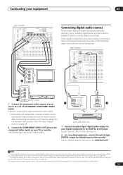
... three-way component video cable. • Since they are assignable, it to tell the receiver which source. After connecting everything, you'll need to one of ASSIGNABLE COMPONENT VIDEO inputs. Connect using a coaxial cable. VSX-1016TXV OPTICAL IN 1 DIGITAL OUT ANTENNA IN 1 IN 2 (DVR/ VCR1) IN 2 (TV...to record some digital sources, you must make analog connections as explained in Connecting analog audio sources below. 15 En Connecting your equipment 03 VSX-1016TXV OPTICAL IN 1 DIGITAL OUT ANTENNA IN 1 IN 2 (DVR/ VCR1) IN 2 (TV/SAT) OUT HDMI IN 3 (CD) ASSIGNABLE...
... three-way component video cable. • Since they are assignable, it to tell the receiver which source. After connecting everything, you'll need to one of ASSIGNABLE COMPONENT VIDEO inputs. Connect using a coaxial cable. VSX-1016TXV OPTICAL IN 1 DIGITAL OUT ANTENNA IN 1 IN 2 (DVR/ VCR1) IN 2 (TV...to record some digital sources, you must make analog connections as explained in Connecting analog audio sources below. 15 En Connecting your equipment 03 VSX-1016TXV OPTICAL IN 1 DIGITAL OUT ANTENNA IN 1 IN 2 (DVR/ VCR1) IN 2 (TV/SAT) OUT HDMI IN 3 (CD) ASSIGNABLE...
Owner's Manual
Page 16
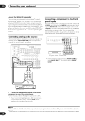
Connecting analog audio sources This receiver features two stereo audio-only inputs. VIDEO VIDEO/GAME INPUT VIDEO L AUDIO R DIGITAL IN MCACC SETUP MIC OPTICAL IN 1 DIGITAL OUT ANTENNA IN 1 IN 2 (DVR/ ... TUNING/ STATION TUNER EDIT SPEAKERS MULTI JOG S - FRONT WOOFER ROUND OUT IN MONITOR OUT OUT IN L CENTER DVR/VCR2 R FRONT SUB WOOFER MULTI CH IN VSX-1016TXV VIDEO/AUDIO OUTPUT DIGITAL OUT TV game, video camera, etc. • Select these inputs (CD-R/TAPE/MD) has corresponding outputs for any kind of audio...
Connecting analog audio sources This receiver features two stereo audio-only inputs. VIDEO VIDEO/GAME INPUT VIDEO L AUDIO R DIGITAL IN MCACC SETUP MIC OPTICAL IN 1 DIGITAL OUT ANTENNA IN 1 IN 2 (DVR/ ... TUNING/ STATION TUNER EDIT SPEAKERS MULTI JOG S - FRONT WOOFER ROUND OUT IN MONITOR OUT OUT IN L CENTER DVR/VCR2 R FRONT SUB WOOFER MULTI CH IN VSX-1016TXV VIDEO/AUDIO OUTPUT DIGITAL OUT TV game, video camera, etc. • Select these inputs (CD-R/TAPE/MD) has corresponding outputs for any kind of audio...
Owner's Manual
Page 17
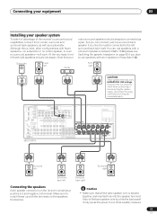
... PR Y PB PR ASSIGNABLE 1 3 S-VIDEO IN IN OUT IN VIDEO OUT IN IN IN OUT IN CD-R/TAPE/MD DVD/LD TV/SAT DVR/VCR1 VSX-1016TXV AM LOOP L OUT PRE OUT CENTER L L (Single) IN 3 R R SUB R SUR- SURROUND FRONT WOOFER ROUND BACK OUT IN MONITOR OUT SPEAKERS A R FRONT ...the terminals on the speakers themselves. At the very least, front left Surround back right Connecting the speakers Each speaker connection on the receiver comprises a positive (+) and negative (-) terminal. To prevent the risk of electric shock when connecting or disconnecting the speaker cables, ...
... PR Y PB PR ASSIGNABLE 1 3 S-VIDEO IN IN OUT IN VIDEO OUT IN IN IN OUT IN CD-R/TAPE/MD DVD/LD TV/SAT DVR/VCR1 VSX-1016TXV AM LOOP L OUT PRE OUT CENTER L L (Single) IN 3 R R SUB R SUR- SURROUND FRONT WOOFER ROUND BACK OUT IN MONITOR OUT SPEAKERS A R FRONT ...the terminals on the speakers themselves. At the very least, front left Surround back right Connecting the speakers Each speaker connection on the receiver comprises a positive (+) and negative (-) terminal. To prevent the risk of electric shock when connecting or disconnecting the speaker cables, ...

Owner's Manual
Page 20
...best possible reception, suspend horizontally outdoors. Never make a knot in after you have connected all your nearest Pioneer authorized independent service company for a replacement. • The receiver should not be disconnected by removing the mains plug from the wall socket when not in order to ...terminal. The power cords should not exceed 100 W (0.8 A). 03 Connecting your hands are not likely to be stepped on and off by the receiver's power switch. A damaged power cord can exceed the 100 W maximum when playing sources at a high volume, this could cause a short circuit...
...best possible reception, suspend horizontally outdoors. Never make a knot in after you have connected all your nearest Pioneer authorized independent service company for a replacement. • The receiver should not be disconnected by removing the mains plug from the wall socket when not in order to ...terminal. The power cords should not exceed 100 W (0.8 A). 03 Connecting your hands are not likely to be stepped on and off by the receiver's power switch. A damaged power cord can exceed the 100 W maximum when playing sources at a high volume, this could cause a short circuit...
Owner's Manual
Page 21
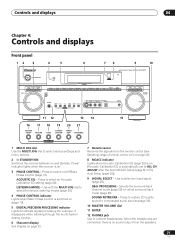
...for example, it disappears when listening through the multichannel analog inputs). 6 Character display See Display on page 23. 7 Remote sensor Receives the signals from the speakers. 21 En Use with the MULTI JOG dial to select the various listening modes (page 26). 4...to connect headphones. Controls and displays 04 Chapter 4: Controls and displays Front panel 12 3 4 5 6 78 9 10 AUDIO/VIDEO MULTI-CHANNEL RECEIVER VSX-1016TXV STANDBY/ON PHASE CONTROL PHASE ACOUSTIC LISTENING CONTROL EQ MODE MULTI JOG DIGITAL PRECISION PROCESSING DVD / LD TV /SAT DVR /VCR1 DVR / VCR2...
...for example, it disappears when listening through the multichannel analog inputs). 6 Character display See Display on page 23. 7 Remote sensor Receives the signals from the speakers. 21 En Use with the MULTI JOG dial to select the various listening modes (page 26). 4...to connect headphones. Controls and displays 04 Chapter 4: Controls and displays Front panel 12 3 4 5 6 78 9 10 AUDIO/VIDEO MULTI-CHANNEL RECEIVER VSX-1016TXV STANDBY/ON PHASE CONTROL PHASE ACOUSTIC LISTENING CONTROL EQ MODE MULTI JOG DIGITAL PRECISION PROCESSING DVD / LD TV /SAT DVR /VCR1 DVR / VCR2...

Owner's Manual
Page 22
...43). Operating range of remote control unit The remote control may not work properly if: • There are obstacles between the remote control and the receiver's remote sensor. • Direct sunlight or fluorescent light is shining onto the remote sensor. • The... receiver is located near a device that is emitting infrared rays. • The receiver is operated simultaneously with the MULTI JOG dial to memorize and name stations for recall (page 31). 21 SPEAKERS Use to select preset ...
...43). Operating range of remote control unit The remote control may not work properly if: • There are obstacles between the remote control and the receiver's remote sensor. • Direct sunlight or fluorescent light is shining onto the remote sensor. • The... receiver is located near a device that is emitting infrared rays. • The receiver is operated simultaneously with the MULTI JOG dial to memorize and name stations for recall (page 31). 21 SPEAKERS Use to select preset ...

Owner's Manual
Page 23
...SR+ 15 1 SIGNAL indicators Light to indicate 2Pro Logic II / 2Pro Logic IIx decoding (page 26). Lights when the mono mode is being received. Right front channel SL - Low frequency effects channel 3 Digital format indicators Light when a signal encoded in the corresponding format is detected. 4 ...Pro 96/24 SBL SB SBR LFE VIDEO CONV. Lights when a Standard Surround mode is switched on page 26). 12 SLEEP Lights when the receiver is enabled (page 48). 6 V.SB Lights during Virtual surround back processing (page 29). 7 Sound processing indicators Light according to reduce it....
...SR+ 15 1 SIGNAL indicators Light to indicate 2Pro Logic II / 2Pro Logic IIx decoding (page 26). Lights when the mono mode is being received. Right front channel SL - Low frequency effects channel 3 Digital format indicators Light when a signal encoded in the corresponding format is detected. 4 ...Pro 96/24 SBL SB SBR LFE VIDEO CONV. Lights when a Standard Surround mode is switched on page 26). 12 SLEEP Lights when the receiver is enabled (page 48). 6 V.SB Lights during Virtual surround back processing (page 29). 7 Sound processing indicators Light according to reduce it....


