
Service Manual
Page 1
... service manual should be used together with the following manual(s): Model No. PCB CONNECTION DIAGRAM 28 3.1 HN MODULE ASSY 28 4. ORDER NO. CONTRAST OF MISCELLANEOUS PARTS 2 2. IC INFORMATION 33 PIONEER CORPORATION 4-1, Meguro 1-chome, Meguro-ku, Tokyo 153-8654, Japan PIONEER ELECTRONICS (USA) INC. Box 1760, Long Beach, CA 90801-1760, U.S.A. P.O. Order No. ARP3400 PLASMA DISPLAY PRO-607PU THIS MANUAL IS APPLICABLE TO THE FOLLOWING MODEL(S) AND TYPE(S). TROUBLESHOOTING...
... service manual should be used together with the following manual(s): Model No. PCB CONNECTION DIAGRAM 28 3.1 HN MODULE ASSY 28 4. ORDER NO. CONTRAST OF MISCELLANEOUS PARTS 2 2. IC INFORMATION 33 PIONEER CORPORATION 4-1, Meguro 1-chome, Meguro-ku, Tokyo 153-8654, Japan PIONEER ELECTRONICS (USA) INC. Box 1760, Long Beach, CA 90801-1760, U.S.A. P.O. Order No. ARP3400 PLASMA DISPLAY PRO-607PU THIS MANUAL IS APPLICABLE TO THE FOLLOWING MODEL(S) AND TYPE(S). TROUBLESHOOTING...
Service Manual
Page 2
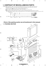
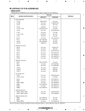
...in the following examples. The mark found on product are not in the service manual for the base model. in our Master Spare Parts List. When ordering resistors, first convert resistance values into code form as in high precision metal film resistors). 5.62k 562 x 101 ...used for noise filter Bead band x3 23 C 16 2 5 12 15 18 15 17 1 D 4 3 2 1 20 22 PRO-607HD 2 3 24 19 26 10 23 21 24 4 Therefore, when replacing, be sure to mark on some component parts indicates the importance of the safety factor of identical designation. A Screws adjacent to use parts of the part...
...in the following examples. The mark found on product are not in the service manual for the base model. in our Master Spare Parts List. When ordering resistors, first convert resistance values into code form as in high precision metal film resistors). 5.62k 562 x 101 ...used for noise filter Bead band x3 23 C 16 2 5 12 15 18 15 17 1 D 4 3 2 1 20 22 PRO-607HD 2 3 24 19 26 10 23 21 24 4 Therefore, when replacing, be sure to mark on some component parts indicates the importance of the safety factor of identical designation. A Screws adjacent to use parts of the part...
Service Manual
Page 4
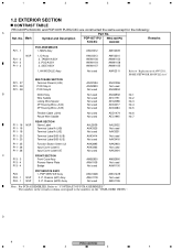
... ADD1474 AEC1945 Refer to the numbers on the " EXPLODED VIEWS ". No. Mark Symbol and Description PDP-6071PU KUCXC PRO-607PU KUCXC Remarks P21 - 1 P21 - 2 P21 - 3 P11 - 2 NSP PCB ASSEMBLIES 1..MAIN Assy 1..IO Assy 2..TANSHI ASSY 2..POD ASSY 2..SIDE ASSY 1..HN MODULE Assy P21 - 37 P21 - 38 P21 - 38 B MULTI BASE SECTION Terminal Panel A (U/B) POD Stay A POD Stay...
... ADD1474 AEC1945 Refer to the numbers on the " EXPLODED VIEWS ". No. Mark Symbol and Description PDP-6071PU KUCXC PRO-607PU KUCXC Remarks P21 - 1 P21 - 2 P21 - 3 P11 - 2 NSP PCB ASSEMBLIES 1..MAIN Assy 1..IO Assy 2..TANSHI ASSY 2..POD ASSY 2..SIDE ASSY 1..HN MODULE Assy P21 - 37 P21 - 38 P21 - 38 B MULTI BASE SECTION Terminal Panel A (U/B) POD Stay A POD Stay...
Service Manual
Page 6
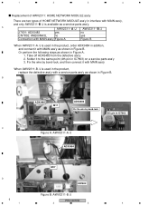
... ADX3483 Fix the wire by bond-lock, and then connect it to the same point (4th pin in IC7803 C Figure A: AWV2311-A /J ADX3484 M17 D CN7802 Figure B: AWV2311-B /J 6 PRO-607HD 1 2 3 4 1 2 3 4 Replacement of AWV2311: HOME NETWORK MODULE ass'y There are two types of HOME NETWORK MODULE ass'y in interface with MAIN ass'y, and only AWV2311-B /J is used in the product, replace the...
... ADX3483 Fix the wire by bond-lock, and then connect it to the same point (4th pin in IC7803 C Figure A: AWV2311-A /J ADX3484 M17 D CN7802 Figure B: AWV2311-B /J 6 PRO-607HD 1 2 3 4 1 2 3 4 Replacement of AWV2311: HOME NETWORK MODULE ass'y There are two types of HOME NETWORK MODULE ass'y in interface with MAIN ass'y, and only AWV2311-B /J is used in the product, replace the...
Service Manual
Page 7
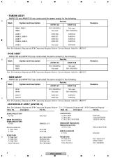
... PRO-607HD 5 6 7 8 A B C D 7 5 6 7 8 CONTRAST OF PCB ASSEMBLIES • MAIN ASSY AWV2309 and AWV2312 are constructed the same except for the following : Mark Symbol and Description Part No. Refer to "Service Manual: Order No. AWV2312 AWV2309 [DT AV BLOCK] IC7105 IC7108 Q7102 C7135 C7136, C7138 C7178 F7105 L7103, L7104 L7106 R7173 R7112 R7163 CN7101 R5520H001B Not used...
... PRO-607HD 5 6 7 8 A B C D 7 5 6 7 8 CONTRAST OF PCB ASSEMBLIES • MAIN ASSY AWV2309 and AWV2312 are constructed the same except for the following : Mark Symbol and Description Part No. Refer to "Service Manual: Order No. AWV2312 AWV2309 [DT AV BLOCK] IC7105 IC7108 Q7102 C7135 C7136, C7138 C7178 F7105 L7103, L7104 L7106 R7173 R7112 R7163 CN7101 R5520H001B Not used...
Service Manual
Page 8
... Schematic Diagram and PCB Connection Diagram. Refer to " 2.4 - 2-9 Schematic Diagram and 3. AWW1157 AWW1155 R9141 R9142 RS1/16SS0R0J Not used Not used RS1/16SS0R0J Remarks JA9101 AKB1303 AKB1304 C JA9102 AKB1305 AKB1306 Note: For Schematic Diagram and PCB Connection Diagram. ARP3395" • SIDE ASSY AWW1155 and AWW1157 are constructed the same except for the following : B Mark Symbol and Description Part No. Description Part No. Refer to "Service Manual...
... Schematic Diagram and PCB Connection Diagram. Refer to " 2.4 - 2-9 Schematic Diagram and 3. AWW1157 AWW1155 R9141 R9142 RS1/16SS0R0J Not used Not used RS1/16SS0R0J Remarks JA9101 AKB1303 AKB1304 C JA9102 AKB1305 AKB1306 Note: For Schematic Diagram and PCB Connection Diagram. ARP3395" • SIDE ASSY AWW1155 and AWW1157 are constructed the same except for the following : B Mark Symbol and Description Part No. Description Part No. Refer to "Service Manual...
Service Manual
Page 10
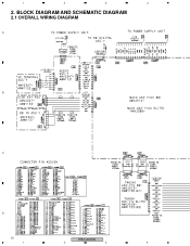
1 2 3 4 2. BLOCK DIAGRAM AND SCHEMATIC DIAGRAM 2.1 OVERALL WIRING DIAGRAM A B C D 10 PRO-607HD 1 2 3 4
1 2 3 4 2. BLOCK DIAGRAM AND SCHEMATIC DIAGRAM 2.1 OVERALL WIRING DIAGRAM A B C D 10 PRO-607HD 1 2 3 4
Service Manual
Page 11
5 6 7 8 A B for AWV2311-A for AWV2311-B PRO-607HD 5 6 7 C D 11 8
5 6 7 8 A B for AWV2311-A for AWV2311-B PRO-607HD 5 6 7 C D 11 8
Service Manual
Page 12
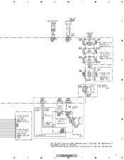
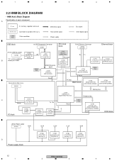
... Memory bus IC7601 EM8620L-LFC [Digital Media Processor] Peripheral bus IC7857 C TC74LCX125 Reset [3-state Buffer] Tx / Rx I/O block IC7852 TC7S00F [NAND] IC7851 PST596IN [Reset IC] IC7852 TC74LCX04 [Inverter] Reset 27MHz X'tal IC7703 AGC1027-A-PI (S29GL128N90TFIR2) [Flash Memory (128Mbit)] Reset DDR block +5V for USB Bus-power *CN7802 * Or, a wire is soldered IC7803 R5520H001B [USB High-side Switch] +5V L7801 ATH7015[C. X7851...
... Memory bus IC7601 EM8620L-LFC [Digital Media Processor] Peripheral bus IC7857 C TC74LCX125 Reset [3-state Buffer] Tx / Rx I/O block IC7852 TC7S00F [NAND] IC7851 PST596IN [Reset IC] IC7852 TC74LCX04 [Inverter] Reset 27MHz X'tal IC7703 AGC1027-A-PI (S29GL128N90TFIR2) [Flash Memory (128Mbit)] Reset DDR block +5V for USB Bus-power *CN7802 * Or, a wire is soldered IC7803 R5520H001B [USB High-side Switch] +5V L7801 ATH7015[C. X7851...
Service Manual
Page 13
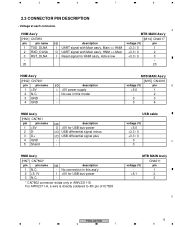
... 1 N.C. 2 +5.1V 3 N.C. No connection in this model - - For AWV2311-A, a wire is directly soldered to 4th pin of IC78.03 MTB MAIN Ass'y CN4011 voltage (V) pin - 1 +5.1 2 - 3 D PRO-607HD 13 5 6 7 8 MTB MAIN Ass'y [M15] CN4016 voltage (V) pin B +5.0 1 - 2 0 3 0 4 HNM Ass'y [HN3] CN7801 pin pin name 1 +5V 2 D- 3 D+ 4 GND 5 Sheild I/O description O +5V for USB bus-power I/O USB differential signal minus I +5V power supply - HNM Ass...
... 1 N.C. 2 +5.1V 3 N.C. No connection in this model - - For AWV2311-A, a wire is directly soldered to 4th pin of IC78.03 MTB MAIN Ass'y CN4011 voltage (V) pin - 1 +5.1 2 - 3 D PRO-607HD 13 5 6 7 8 MTB MAIN Ass'y [M15] CN4016 voltage (V) pin B +5.0 1 - 2 0 3 0 4 HNM Ass'y [HN3] CN7801 pin pin name 1 +5V 2 D- 3 D+ 4 GND 5 Sheild I/O description O +5V for USB bus-power I/O USB differential signal minus I +5V power supply - HNM Ass...
Service Manual
Page 23
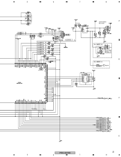
5 6 7 8 A USB POWER SECTION B C D PRO-607HD 23 5 6 7 8
5 6 7 8 A USB POWER SECTION B C D PRO-607HD 23 5 6 7 8
Service Manual
Page 28
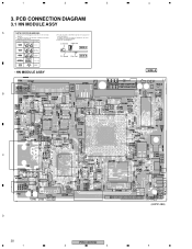
... A C D 28 1 PRO-607HD 2 3 (ANP2148B) 4 A comparison between the main parts of PCB diagrams. Connector Capacitor BCE Transistor B C EB C E SIDE A BCE Transistor with the schematic diagram. 4. Part numbers in PCB diagrams match those in the schematic diagrams. 2. PCB CONNECTION DIAGRAM 3.1 HN MODULE ASSY A NOTE FOR PCB DIAGRAMS : 1. For further information for several destinations. 1 2 3 3. Symbol In PCB Diagrams Symbol In Schematic Diagrams B C EB C E Part Name 3. View point of PCB and schematic diagrams is...
... A C D 28 1 PRO-607HD 2 3 (ANP2148B) 4 A comparison between the main parts of PCB diagrams. Connector Capacitor BCE Transistor B C EB C E SIDE A BCE Transistor with the schematic diagram. 4. Part numbers in PCB diagrams match those in the schematic diagrams. 2. PCB CONNECTION DIAGRAM 3.1 HN MODULE ASSY A NOTE FOR PCB DIAGRAMS : 1. For further information for several destinations. 1 2 3 3. Symbol In PCB Diagrams Symbol In Schematic Diagrams B C EB C E Part Name 3. View point of PCB and schematic diagrams is...
Service Manual
Page 30
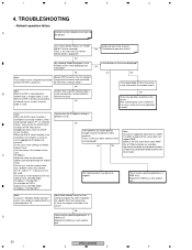
... Note: The network server should be played! Before PDP turned on, has the network server been turned on and connected to use the number which can not be connected before the PDP's power-on "HOME MENU" GUI be something defective in the network. If the contents can not be played though it needs to the sheet of 720p resolution are available. Below is WMV. TROUBLESHOOTING • Network operation failure...
... Note: The network server should be played! Before PDP turned on, has the network server been turned on and connected to use the number which can not be connected before the PDP's power-on "HOME MENU" GUI be something defective in the network. If the contents can not be played though it needs to the sheet of 720p resolution are available. Below is WMV. TROUBLESHOOTING • Network operation failure...
Service Manual
Page 31
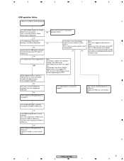
... into both side: PDP and the USB device. D PRO-607HD 31 5 6 7 8 For example, most of the supported video format is correctly inserted into CN7801 in MAIN ass'y. The other end is there any USB device available, can be selected, try a multi card reader instead of IC7803 in HNM ass'y. 5 6 7 8 • USB operation failure A picture via USB can be played? yes Is the...
... into both side: PDP and the USB device. D PRO-607HD 31 5 6 7 8 For example, most of the supported video format is correctly inserted into CN7801 in MAIN ass'y. The other end is there any USB device available, can be selected, try a multi card reader instead of IC7803 in HNM ass'y. 5 6 7 8 • USB operation failure A picture via USB can be played? yes Is the...
Service Manual
Page 32
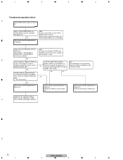
... CN7901 and CN4016. D 32 PRO-607HD 1 2 3 4 No There may be something defective in the product. Please wait for about 40 seconds until "Home Media Gallery" turns selectable. yes Almost 35 seconds after power-on? No To make analysis, remove the wire No yes ass'y ...M14]CN4017 [HN2]CN7901[M15]CN4016 Isn't there any pulse signal observed on , is used. 1 2 3 4 • Fundamental operation failure A "Home Media Gallery" does not work at all! C That is Q4102 and the parts around it to start "Home Media Gallery" function. Is +5V still not there? Note: It...
... CN7901 and CN4016. D 32 PRO-607HD 1 2 3 4 No There may be something defective in the product. Please wait for about 40 seconds until "Home Media Gallery" turns selectable. yes Almost 35 seconds after power-on? No To make analysis, remove the wire No yes ass'y ...M14]CN4017 [HN2]CN7901[M15]CN4016 Isn't there any pulse signal observed on , is used. 1 2 3 4 • Fundamental operation failure A "Home Media Gallery" does not work at all! C That is Q4102 and the parts around it to start "Home Media Gallery" function. Is +5V still not there? Note: It...
Service Manual
Page 33
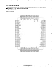
IC INFORMATION • The information shown in the list is basic information and may not correspond exactly to that shown in the schematic diagrams. RTL8100CL-LF (HN MODULE Assy: IC7754) A • Ethernet Controller IC Pin Arrangement B C D PRO-607HD 33 5 6 7 8 5 6 7 8 5.
IC INFORMATION • The information shown in the list is basic information and may not correspond exactly to that shown in the schematic diagrams. RTL8100CL-LF (HN MODULE Assy: IC7754) A • Ethernet Controller IC Pin Arrangement B C D PRO-607HD 33 5 6 7 8 5 6 7 8 5.


