
Service Manual
Page 1
Order No. ARP3395 SCHEMATIC DIAGRAM and PCB CONNECTION DIAGRAM CONTENTS 1. P.O. IC INFORMATION 33 PIONEER CORPORATION 4-1, Meguro 1-chome, Meguro-ku, Tokyo 153-8654, Japan PIONEER ELECTRONICS (USA) INC. Model Type Power Requirement Remarks PRO-607PU KUCXC AC120 V ¶ This service manual should be used together with the following manual(s): Model No. PIONEER EUROPE NV Haven 1087, Keetberglaan 1, 9120 Melsele...
Order No. ARP3395 SCHEMATIC DIAGRAM and PCB CONNECTION DIAGRAM CONTENTS 1. P.O. IC INFORMATION 33 PIONEER CORPORATION 4-1, Meguro 1-chome, Meguro-ku, Tokyo 153-8654, Japan PIONEER ELECTRONICS (USA) INC. Model Type Power Requirement Remarks PRO-607PU KUCXC AC120 V ¶ This service manual should be used together with the following manual(s): Model No. PIONEER EUROPE NV Haven 1087, Keetberglaan 1, 9120 Melsele...
Service Manual
Page 7
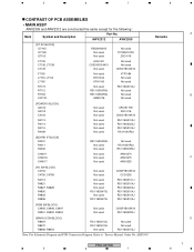
ARP3395" Remarks PRO-607HD 5 6 7 8 A B C D 7 AWV2312 AWV2309 [DT AV BLOCK] IC7105 IC7108 Q7102 C7135 C7136, C7138 C7178 F7105 L7103, L7104 L7106 R7173 R7112 R7163 CN7101 R5520H001B Not used Not ... RS1/16SS220J [MAIN UCOM BLOCK] R8454 R8470 R8469, R8453 RS1/16SS103J RS1/16SS103J Not used Not used Not used RS1/16SS103J Note: For Schematic Diagram and PCB Connection Diagram. Refer to "Service Manual: Order No. 5 6 7 8 CONTRAST OF PCB ASSEMBLIES • MAIN ASSY AWV2309 and AWV2312 are constructed the same except for the...
ARP3395" Remarks PRO-607HD 5 6 7 8 A B C D 7 AWV2312 AWV2309 [DT AV BLOCK] IC7105 IC7108 Q7102 C7135 C7136, C7138 C7178 F7105 L7103, L7104 L7106 R7173 R7112 R7163 CN7101 R5520H001B Not used Not ... RS1/16SS220J [MAIN UCOM BLOCK] R8454 R8470 R8469, R8453 RS1/16SS103J RS1/16SS103J Not used Not used Not used RS1/16SS103J Note: For Schematic Diagram and PCB Connection Diagram. Refer to "Service Manual: Order No. 5 6 7 8 CONTRAST OF PCB ASSEMBLIES • MAIN ASSY AWV2309 and AWV2312 are constructed the same except for the...
Service Manual
Page 8
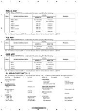
...16SS0R0J Not used Not used RS1/16SS0R0J Remarks JA9101 AKB1303 AKB1304 C JA9102 AKB1305 AKB1306 Note: For Schematic Diagram and PCB Connection Diagram. PCB Connection Diagram" Mark No. SEMICONDUCTORS IC7703 [8620 BLOCK(U)] SEMICONDUCTORS IC7601 MISCELLANEOUS F 7601,7602 X 7601 RESISTORS D R...F 7701 RESISTORS R 7709,7710 R 7711-7718 Other Resistors DCH1201 CCSSCH7R0D50 CKSSYF104Z16 EDD2516AKTA-6B ATL7002 RS1/16SS1001F RAB4CQ560J RS1/16SS###J 8 PRO-607HD 1 2 3 4 Refer to "Service Manual: Order No. Mark No. Refer to "Service Manual: Order No. Description...
...16SS0R0J Not used Not used RS1/16SS0R0J Remarks JA9101 AKB1303 AKB1304 C JA9102 AKB1305 AKB1306 Note: For Schematic Diagram and PCB Connection Diagram. PCB Connection Diagram" Mark No. SEMICONDUCTORS IC7703 [8620 BLOCK(U)] SEMICONDUCTORS IC7601 MISCELLANEOUS F 7601,7602 X 7601 RESISTORS D R...F 7701 RESISTORS R 7709,7710 R 7711-7718 Other Resistors DCH1201 CCSSCH7R0D50 CKSSYF104Z16 EDD2516AKTA-6B ATL7002 RS1/16SS1001F RAB4CQ560J RS1/16SS###J 8 PRO-607HD 1 2 3 4 Refer to "Service Manual: Order No. Mark No. Refer to "Service Manual: Order No. Description...
Service Manual
Page 10
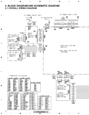
1 2 3 4 2. BLOCK DIAGRAM AND SCHEMATIC DIAGRAM 2.1 OVERALL WIRING DIAGRAM A B C D 10 PRO-607HD 1 2 3 4
1 2 3 4 2. BLOCK DIAGRAM AND SCHEMATIC DIAGRAM 2.1 OVERALL WIRING DIAGRAM A B C D 10 PRO-607HD 1 2 3 4
Service Manual
Page 12
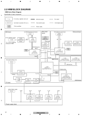
... Power supply CN7901 +5.0V D Power supply block +3.3V +2.5V +1.2V -5.0V IC7903 LTC3412EFE [SW Reg. IC] IC7901 LM2664M6X [Converter IC] 12 PRO-607HD 1 2 3 4 1 2 3 4 2.2 HNM BLOCK DIAGRAM • HNM Ass'y Block Diagram Classification of each component A IC xxxx IC, memory, regulator and so on CN (JA) xxxx Connector to outside of the ass'y xx...
... Power supply CN7901 +5.0V D Power supply block +3.3V +2.5V +1.2V -5.0V IC7903 LTC3412EFE [SW Reg. IC] IC7901 LM2664M6X [Converter IC] 12 PRO-607HD 1 2 3 4 1 2 3 4 2.2 HNM BLOCK DIAGRAM • HNM Ass'y Block Diagram Classification of each component A IC xxxx IC, memory, regulator and so on CN (JA) xxxx Connector to outside of the ass'y xx...
Service Manual
Page 28
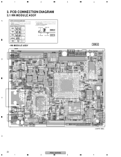
... Chip Part SIDE B Resistor array 3-terminal regulator • HN MODULE ASSY B 4 SIDE A C D 28 1 PRO-607HD 2 3 (ANP2148B) 4 1 2 3 3. PCB CONNECTION DIAGRAM 3.1 HN MODULE ASSY A NOTE FOR PCB DIAGRAMS : 1. Symbol In PCB Diagrams Symbol In Schematic Diagrams B C EB C E Part Name 3. A comparison between the main parts of PCB diagrams. Connector Capacitor BCE Transistor B C EB C E SIDE A BCE Transistor with the schematic...
... Chip Part SIDE B Resistor array 3-terminal regulator • HN MODULE ASSY B 4 SIDE A C D 28 1 PRO-607HD 2 3 (ANP2148B) 4 1 2 3 3. PCB CONNECTION DIAGRAM 3.1 HN MODULE ASSY A NOTE FOR PCB DIAGRAMS : 1. Symbol In PCB Diagrams Symbol In Schematic Diagrams B C EB C E Part Name 3. A comparison between the main parts of PCB diagrams. Connector Capacitor BCE Transistor B C EB C E SIDE A BCE Transistor with the schematic...
Service Manual
Page 33
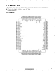
5 6 7 8 5. IC INFORMATION • The information shown in the list is basic information and may not correspond exactly to that shown in the schematic diagrams. RTL8100CL-LF (HN MODULE Assy: IC7754) A • Ethernet Controller IC Pin Arrangement B C D PRO-607HD 33 5 6 7 8
5 6 7 8 5. IC INFORMATION • The information shown in the list is basic information and may not correspond exactly to that shown in the schematic diagrams. RTL8100CL-LF (HN MODULE Assy: IC7754) A • Ethernet Controller IC Pin Arrangement B C D PRO-607HD 33 5 6 7 8