Owner's Manual
Page 4
...Setting for buying this Pioneer product. However the method of connecting and operating the unit is the same. 01 Important User Guidance Information 02 Safety Precautions 03 Operational Precautions 04 Supplied Accessories Plasma Display 11 Media Receiver 11 05 Part Names Plasma Display 12 Media ... the instructions, put them away in the explanatory drawings. Contents Thank you for skipping unwanted channels 31 Setting up TV channels manually 31 Naming TV channels 32 Checking signal strength 32 Checking the Cable Card ID 32 Enabling data acquisition 32 Parental Control 33 Changing ...
...Setting for buying this Pioneer product. However the method of connecting and operating the unit is the same. 01 Important User Guidance Information 02 Safety Precautions 03 Operational Precautions 04 Supplied Accessories Plasma Display 11 Media Receiver 11 05 Part Names Plasma Display 12 Media ... the instructions, put them away in the explanatory drawings. Contents Thank you for skipping unwanted channels 31 Setting up TV channels manually 31 Naming TV channels 32 Checking signal strength 32 Checking the Cable Card ID 32 Enabling data acquisition 32 Parental Control 33 Changing ...
Owner's Manual
Page 5
...Adjusting image positions (AV mode only 44 Adjusting image positions and clock automatically (PC mode only 45 Adjusting image positions and clock manually (PC mode only 45 Selecting a screen size 46 Changing the brightness at both sides of the screen (Side Mask 47 ...47 11 Timer Presetting Presetting TV programs using the timer 48 Priority rules for overlapped presettings 49 12 Enjoying through External Equipment Watching a DVD image 50 Connecting a DVD player 50 Displaying a DVD image 50 Watching a VCR image 50 Connecting a VCR 50 Displaying a VCR image 50 Using HDMI Input 51 ...
...Adjusting image positions (AV mode only 44 Adjusting image positions and clock automatically (PC mode only 45 Adjusting image positions and clock manually (PC mode only 45 Selecting a screen size 46 Changing the brightness at both sides of the screen (Side Mask 47 ...47 11 Timer Presetting Presetting TV programs using the timer 48 Priority rules for overlapped presettings 49 12 Enjoying through External Equipment Watching a DVD image 50 Connecting a DVD player 50 Displaying a DVD image 50 Watching a VCR image 50 Connecting a VCR 50 Displaying a VCR image 50 Using HDMI Input 51 ...
Owner's Manual
Page 8
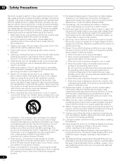
... damage, which often requires extensive adjustment work , request the service technician to perform safety checks to ensure that the product is in this manual in a safe place for built-in fire or personal injury. 24. b. Improper adjustment of glass. When the product displays an abnormal ... property damage if improperly handled. When the product has been exposed to clean the product. f. Do not expose the Plasma Display to direct sunlight for the PDP-434PU. Keep this product is damaged. When mounting the product on the product and in the instructions must be kept ...
... damage, which often requires extensive adjustment work , request the service technician to perform safety checks to ensure that the product is in this manual in a safe place for built-in fire or personal injury. 24. b. Improper adjustment of glass. When the product displays an abnormal ... property damage if improperly handled. When the product has been exposed to clean the product. f. Do not expose the Plasma Display to direct sunlight for the PDP-434PU. Keep this product is damaged. When mounting the product on the product and in the instructions must be kept ...
Owner's Manual
Page 9
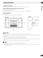
... Observe the following six mounting holes can be used for the installation: Rear view Side view Mounting surface Mounting hole Mounting hole Median line Plasma Display Mounting bracket (or equivalent item) M8 screw 12 to 18 mm (0.5 to 0.7 inches) Median line • Be sure to ...which go 12 to 18 mm (0.5 to use the supplied bolts. • For details, see the instruction manual that results from the mounting surface of mounting items other than the optional PIONEER products. 9 En When using other items • Consult your dealer to perform the installation. • Be...
... Observe the following six mounting holes can be used for the installation: Rear view Side view Mounting surface Mounting hole Mounting hole Median line Plasma Display Mounting bracket (or equivalent item) M8 screw 12 to 18 mm (0.5 to 0.7 inches) Median line • Be sure to ...which go 12 to 18 mm (0.5 to use the supplied bolts. • For details, see the instruction manual that results from the mounting surface of mounting items other than the optional PIONEER products. 9 En When using other items • Consult your dealer to perform the installation. • Be...
Owner's Manual
Page 15
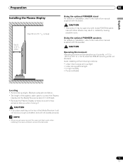
... Locating • Avoid direct sunlight. Preparation Installing the Plasma Display Over 50 cm (19 /11 16 inches) Over 10 cm (3 15/ 16 inches ) 06 Using the optional PIONEER stand For details on installation, refer to the instruction manual supplied with the stand. • This product may ... anything on installation, refer to connect the Plasma Display and the Media Receiver is about 3 m (9.8 feet). • Because the Plasma Display is heavy, be used to the instruction manual supplied with model PDK-TS04 stand. Using the optional PIONEER speakers For details on the top of the...
... Locating • Avoid direct sunlight. Preparation Installing the Plasma Display Over 50 cm (19 /11 16 inches) Over 10 cm (3 15/ 16 inches ) 06 Using the optional PIONEER stand For details on installation, refer to the instruction manual supplied with the stand. • This product may ... anything on installation, refer to connect the Plasma Display and the Media Receiver is about 3 m (9.8 feet). • Because the Plasma Display is heavy, be used to the instruction manual supplied with model PDK-TS04 stand. Using the optional PIONEER speakers For details on the top of the...
Owner's Manual
Page 18
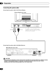
System cable Connecting the system cable to the instruction manual that came with the speaker. 06 Preparation Connecting the system cable Connecting the system cable to the Plasma Display Plasma Display (rear view) (WHITE) (BLACK) For details on optional PIONEER speaker installation, refer to the Media Receiver Media Receiver (rear view) IN OUT VCR CONTROL...
System cable Connecting the system cable to the instruction manual that came with the speaker. 06 Preparation Connecting the system cable Connecting the system cable to the Plasma Display Plasma Display (rear view) (WHITE) (BLACK) For details on optional PIONEER speaker installation, refer to the Media Receiver Media Receiver (rear view) IN OUT VCR CONTROL...
Owner's Manual
Page 24
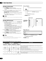
... Receiver turns off and the one on the Plasma Display flashes red. 3 Press POWER on the Plasma Display. • The STANDBY indicator on the Plasma Display turns off the power 1 Press TV on the remote control unit or STANDBY/ON on the Plasma Display. • The system enters the standby.... • It is recommended to place the system into the standby mode by pressing TV on the remote control unit. Plasma Display STANDBY indicator POWER ON indicator POWER button • In this manual, "system" means the Plasma Display Panel and Media Receiver. (right view) Turning off . • You can ...
... Receiver turns off and the one on the Plasma Display flashes red. 3 Press POWER on the Plasma Display. • The STANDBY indicator on the Plasma Display turns off the power 1 Press TV on the remote control unit or STANDBY/ON on the Plasma Display. • The system enters the standby.... • It is recommended to place the system into the standby mode by pressing TV on the remote control unit. Plasma Display STANDBY indicator POWER ON indicator POWER button • In this manual, "system" means the Plasma Display Panel and Media Receiver. (right view) Turning off . • You can ...

Owner's Manual
Page 27
...MONO mode is selected, the Plasma Display System sound remains mono even if the system receives a stereo broadcast. This service presents various types of the MTS/SAP modes selected using HTML text. Setting MTS/SAP mode When watching conventional TV programs, you may manually switch to the MONO mode... is INPUT 1 to view the POD display. • If you can use the POD service provided by the cable TV company. See page 32. In this manual designate TV channels that provides multilanguage services, you can enjoy, for example, sports, shows, and concerts in dynamic stereo sound. •...
...MONO mode is selected, the Plasma Display System sound remains mono even if the system receives a stereo broadcast. This service presents various types of the MTS/SAP modes selected using HTML text. Setting MTS/SAP mode When watching conventional TV programs, you may manually switch to the MONO mode... is INPUT 1 to view the POD display. • If you can use the POD service provided by the cable TV company. See page 32. In this manual designate TV channels that provides multilanguage services, you can enjoy, for example, sports, shows, and concerts in dynamic stereo sound. •...
Owner's Manual
Page 30
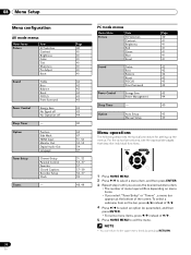
... Adjust Reset Sound Treble Bass Balance Reset FOCUS Front Surround Power Control Energy Save No Signal off No Operation off Sleep Timer - Option Auto Setup Manual Setup Page 40 41 41 41 41 41 41 42 42 42 42 43 43 43 44 40 45 45 Menu operations The following describes...
... Adjust Reset Sound Treble Bass Balance Reset FOCUS Front Surround Power Control Energy Save No Signal off No Operation off Sleep Timer - Option Auto Setup Manual Setup Page 40 41 41 41 41 41 41 42 42 42 42 43 43 43 44 40 45 45 Menu operations The following describes...
Owner's Manual
Page 31
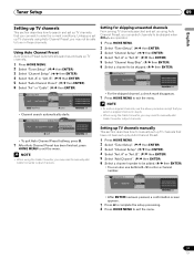
...Keep/Skip". ( / then ENTER) 6 Select a channel to be skipped when CH +/- Setting up TV channels manually This section describes how to manually set up TV channels that have not been set up TV channels that you select a skipped channel in those channels. A Add Channel Add Channel 0000.000 1 ... a confirmation screen appears. 7 Press A to complete the setup processing. 8 Press HOME MENU to manually add Cable Converter output channels. Tuner Setup 09 English Setting up TV channels This section describes how to search and set up by Auto Channel Preset. 1 Press HOME MENU...
...Keep/Skip". ( / then ENTER) 6 Select a channel to be skipped when CH +/- Setting up TV channels manually This section describes how to manually set up TV channels that have not been set up TV channels that you select a skipped channel in those channels. A Add Channel Add Channel 0000.000 1 ... a confirmation screen appears. 7 Press A to complete the setup processing. 8 Press HOME MENU to manually add Cable Converter output channels. Tuner Setup 09 English Setting up TV channels This section describes how to search and set up by Auto Channel Preset. 1 Press HOME MENU...

Owner's Manual
Page 39
...Exit • The date and time will be automatically corrected using / , / and ENTER. Clock Auto/Manual Set Auto/Manual Set •Auto Set Clock Set Channel Ant. Clock Auto/Manual Set Auto/Manual Set •Manual Set Date and Time 3 4 3 /17/04 11:58pm 5 6 Current Time: 11:58 pm PDT... Clock Setting, the system acquires and sets time information automatically. If you cannot view channel banner information, use auto channel select, and preset TV programs for your area. ( / then ENTER) Clock Time Zone Time Zone Atlantic Eastern Central Mountain Current Time: 9:55 pm EDT Monday ...
...Exit • The date and time will be automatically corrected using / , / and ENTER. Clock Auto/Manual Set Auto/Manual Set •Auto Set Clock Set Channel Ant. Clock Auto/Manual Set Auto/Manual Set •Manual Set Date and Time 3 4 3 /17/04 11:58pm 5 6 Current Time: 11:58 pm PDT... Clock Setting, the system acquires and sets time information automatically. If you cannot view channel banner information, use auto channel select, and preset TV programs for your area. ( / then ENTER) Clock Time Zone Time Zone Atlantic Eastern Central Mountain Current Time: 9:55 pm EDT Monday ...
Owner's Manual
Page 40
... Item Description STANDARD For a highly defined image in a normally bright room DYNAMIC For a very sharp image with the maximum contrast This mode does not allow manual image quality adjustment. You can also use the menu to change the options. 1 Press HOME MENU. 2 Select "Picture". ( / then ENTER) 3 ... as desired. AV Selection Select from the five viewing options, depending on the current environment (e.g., room brightness), the type of the current TV program, or the type of images input from external equipment. 1 Press AV SELECTION. • The current AV Selection mode appears. 2...
... Item Description STANDARD For a highly defined image in a normally bright room DYNAMIC For a very sharp image with the maximum contrast This mode does not allow manual image quality adjustment. You can also use the menu to change the options. 1 Press HOME MENU. 2 Select "Picture". ( / then ENTER) 3 ... as desired. AV Selection Select from the five viewing options, depending on the current environment (e.g., room brightness), the type of the current TV program, or the type of images input from external equipment. 1 Press AV SELECTION. • The current AV Selection mode appears. 2...

Owner's Manual
Page 45
... adjust positions and clock of images using Auto Setup. appears. • Even when "Auto Setup completed." Adjusting image positions and clock manually (PC mode only) Usually you can easily adjust the positions and clock of images coming from a personal computer. 1 Press HOME MENU.... 2 Select "Option". ( / then ENTER) 3 Select "Auto Setup". ( / then ENTER) Option Auto Setup Manual Setup 5 Perform adjustment. ( / and / ) • Use / only when you adjust the vertical position after selecting "H/V Position Adjust". 6 Press HOME MENU ...
... adjust positions and clock of images using Auto Setup. appears. • Even when "Auto Setup completed." Adjusting image positions and clock manually (PC mode only) Usually you can easily adjust the positions and clock of images coming from a personal computer. 1 Press HOME MENU.... 2 Select "Option". ( / then ENTER) 3 Select "Auto Setup". ( / then ENTER) Option Auto Setup Manual Setup 5 Perform adjustment. ( / and / ) • Use / only when you adjust the vertical position after selecting "H/V Position Adjust". 6 Press HOME MENU ...

Owner's Manual
Page 50
... game console, camcorder, or other external equipment. • Refer to your DVD player instruction manual for the signal type. • The INPUT 1 terminals are checked for cable connections in the... Video. • Connect external equipment to only terminals that are to be actually used . 50 En AV cable (commercially available) Media Receiver (rear view) Component Video cable (commercially available) ... 1 on the remote control unit or press INPUT on the Plasma Display to select INPUT1. • Refer to your Plasma Display System, like a DVD player, VCR, personal computer, game...
... game console, camcorder, or other external equipment. • Refer to your DVD player instruction manual for the signal type. • The INPUT 1 terminals are checked for cable connections in the... Video. • Connect external equipment to only terminals that are to be actually used . 50 En AV cable (commercially available) Media Receiver (rear view) Component Video cable (commercially available) ... 1 on the remote control unit or press INPUT on the Plasma Display to select INPUT1. • Refer to your Plasma Display System, like a DVD player, VCR, personal computer, game...

Owner's Manual
Page 51
...with the connected equipment. Before starting the menu, press INPUT 1 (or INPUT 3) on the remote control unit or press INPUT on the Plasma Display to exit the menu. Color-1 Digital Component Video signals (4:2:2) locked Color-2 Digital Component Video signals (4:4:4) locked Color-3 Digital RGB signals .... (factory default) Enable Activates the HDMI terminal. 6 Press HOME MENU to identify the type of these signals, see the operation manual that came with the connected equipment. Input signal correlation table 1920∗[email protected]/60Hz 720∗[email protected]/60Hz 1280&#...
...with the connected equipment. Before starting the menu, press INPUT 1 (or INPUT 3) on the remote control unit or press INPUT on the Plasma Display to exit the menu. Color-1 Digital Component Video signals (4:2:2) locked Color-2 Digital Component Video signals (4:4:4) locked Color-3 Digital RGB signals .... (factory default) Enable Activates the HDMI terminal. 6 Press HOME MENU to identify the type of these signals, see the operation manual that came with the connected equipment. Input signal correlation table 1920∗[email protected]/60Hz 720∗[email protected]/60Hz 1280&#...

Owner's Manual
Page 52
...type. • For the audio signal types to be specified, check the operation manual that are checked for example, digital TV programs using the recording equipment. Recording digital TV programs using the supplied VCR controller. Component Video cable (commercially available) Game console/...Camcorder 52 En Avoiding unwanted feedback You can prevent unwanted feedback from the game console or camcorder, press INPUT 4 on the remote control unit or press INPUT on the Plasma...
...type. • For the audio signal types to be specified, check the operation manual that are checked for example, digital TV programs using the recording equipment. Recording digital TV programs using the supplied VCR controller. Component Video cable (commercially available) Game console/...Camcorder 52 En Avoiding unwanted feedback You can prevent unwanted feedback from the game console or camcorder, press INPUT 4 on the remote control unit or press INPUT on the Plasma...

Owner's Manual
Page 53
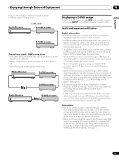
.... Optical digital cable (commercially available) Audio cable (commercially available) AV receiver 53 En For more information, see the instruction manual that came with the AV receiver. Selecting an external input source may result in high quality. Enjoying through External Equipment 12 ... the following signals: 1 Video signals input from the COMPONENT VIDEO terminal 2 Video signals from a personal computer 3 S-Video signals when a conventional TV channel is being received 4 S-Video signals when Video signals (INPUT 1, 2, and 4) are being input 5 Digital video and audio signals from ...
.... Optical digital cable (commercially available) Audio cable (commercially available) AV receiver 53 En For more information, see the instruction manual that came with the AV receiver. Selecting an external input source may result in high quality. Enjoying through External Equipment 12 ... the following signals: 1 Video signals input from the COMPONENT VIDEO terminal 2 Video signals from a personal computer 3 S-Video signals when a conventional TV channel is being received 4 S-Video signals when Video signals (INPUT 1, 2, and 4) are being input 5 Digital video and audio signals from ...
Owner's Manual
Page 55
...TV channels nor contents coming from one of these D-VHS recorders (basic functions only). • Some D-VHS recorders connected through i.LINK may not allow this system. • D-VHS recorders connected through the control panel screen or to two D-VHS recorders that D-VHS recorder. See page 50... i.LINK on the remote control unit or press INPUT on the Plasma Display to be copied from external input sources. • This system...tape, or (if with your D-VHS recorder. Check the instruction manual that does not support the DTCP. Enjoying through External Equipment 12 English...
...TV channels nor contents coming from one of these D-VHS recorders (basic functions only). • Some D-VHS recorders connected through i.LINK may not allow this system. • D-VHS recorders connected through the control panel screen or to two D-VHS recorders that D-VHS recorder. See page 50... i.LINK on the remote control unit or press INPUT on the Plasma Display to be copied from external input sources. • This system...tape, or (if with your D-VHS recorder. Check the instruction manual that does not support the DTCP. Enjoying through External Equipment 12 English...
Owner's Manual
Page 61
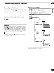
...OUT The control cables (commercially available) are mono sound cables with a PIONEER AV receiver. You can then operate the connected equipment by sending commands...the rear of the Media Receiver supports SR+ that came with the PIONEER AV receiver supporting SR+. • While in connection through External ...Connecting control cords Connect control cords between the Media Receiver and other PIONEER equipment having the logo. After the CONTROL IN terminals have been ...more information, see the instruction manual that allows linked operations with mini plugs (no resistance). 61 En ...
...OUT The control cables (commercially available) are mono sound cables with a PIONEER AV receiver. You can then operate the connected equipment by sending commands...the rear of the Media Receiver supports SR+ that came with the PIONEER AV receiver supporting SR+. • While in connection through External ...Connecting control cords Connect control cords between the Media Receiver and other PIONEER equipment having the logo. After the CONTROL IN terminals have been ...more information, see the instruction manual that allows linked operations with mini plugs (no resistance). 61 En ...


